Advertisement
T echnical
Manual
Table of Contents
Specification.....................................1
Parts List ..........................................2~5
Adjustment.......................................6
Assembled View...............................7~8
PCB Assembly .................................9
Schematic Diagram..........................10
Specification
Continuous Power Output into 8 ohms
(20-20kHz, < 0.03% THD)
2
100 watts/ch into 8 ohms, all channel driven
Continuous Power Output into 4 ohms
(DIN 1 kHz,1.0% THD)
D
170 watts/ch into 4 ohms, all channels driven
Total Harmonic Distortion
o
(20Hz-20kHz, 8 ohms)
2
Continuous rated power. <0.03%
One-half rated power. <0.03%
1 watt power. <0.03%
Intermodulation Distortion
(60 Hz : 7 kHz, 4:1)
< 0.03%
Danping Factor
(20-20,000 Hz, 8 ohms)
>200
Input Impedance
20 k Ohms
Input Sensitivity
1.0 volt
Amplifier Gain:
26 dB
Input Overload Level
5.0 volt
Peak Current
> 60 A
Frequency Response (±1 dB)
4Hz-100kHz
BUNZAN-SHINSEN-BLD. 4F 10-10 SHINSEN-CHO, SHIBUYA-KU,
TOKYO 150-0045, JAPAN
Quality Uncompromised
®
STEREO POWER AMPLIFIER
RKB-2100
S/N Ratio (IHF A)
120 dB
Crosstalk/Separation
> 70 dB
Speaker Impedance
4 ohms minimum
Auto Turn On Level (with all inputs)
3 mV input signal
Power Requirements
USA: 120 Volts, 60 Hz
Europe: 230 Volts, 50 Hz
Power Consumption
450 Watts
Idle: 40 Watts
d
Standby: 2.3 Watts
Dimensions (W x H x D)
(not including rack adaptors)
n
430 x 144 x 328 mm
16.9 x 5.7 x 12.9 in
Weight (net)
11.2 kg, 25 lb.
Panel Height
3U, 132.6 mm/5.2 in
Serial. NO.
Y-383A-0505/pdf
Advertisement
Table of Contents

Related Manuals for Rotel RKB-2100


Summary of Contents for Rotel RKB-2100
-
Page 1: Table Of Contents
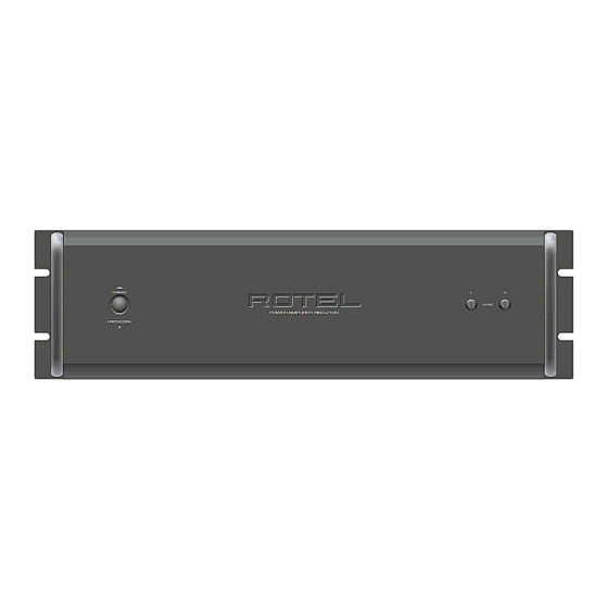
Quality Uncompromised ® T echnical STEREO POWER AMPLIFIER RKB-2100 Manual Table of Contents Specification........1 Parts List ..........2~5 Adjustment........6 Assembled View.......7~8 PCB Assembly .........9 Schematic Diagram......10 Specification Continuous Power Output into 8 ohms S/N Ratio (IHF A) (20-20kHz, < 0.03% THD) - Page 2 RKB-2100 Appearance POWER LEVEL POWER AMPLIFIER RKB-2100 PROTECTION WARNING: TO REDUCE THE RISK OF FIRE OR ELECTRICAL SHOCK, DO NOT EXPOSE THIS EQUIPMENT WARNING 12V TRIG AC BREAKER SHOCK HAZARD—DO NOT OPEN. TO RAIN OR MOISTURE. AVIS: RISQUE DE CHOC ÉLECTRIQUE—NE PAS OUVRIR.
-
Page 3: Parts List 1/3
RKB-2100 Parts List 1/3 SYMBOL PARTS NO. DESCRIPTION 016 X-1428A01-04 PCB ASSY 501 X-1428 PCB ASS'Y (MAIN) H1-H4 017 C-4401A01 SUB HEAT SINKER H1-H4 019 TO-126 MICA SHEET TBM-51W-15 #9524 T002 022 T-1101N01 SUB TRANSFORMER IC661 031 MPC1237HA IC (PROTECTION) - Page 4 RKB-2100 Parts List 2/3 SYMBOL PARTS NO. DESCRIPTION R405,406,623,624,629,630 054 TMF1000 METAL FILM RESISTOR 1/4W 100 R601,602,631,632 054 TMF1001 METAL FILM RESISTOR 1/4W 1K R403,404 054 TMF1002 METAL FILM RESISTOR 1/4W 10K R607-610,615-618 054 TMF1501 METAL FILM RESISTOR 1/4W 1.5K...
- Page 5 RKB-2100 Parts List 3/3 SYMBOL PARTS NO. DESCRIPTION 011 FP-583-B BLACK PANEL ASSY 012 RV4-09A00 PUSH BUTTON 14Φ (BLACK) 012 VF4-10C00 KNOB 10Φ (BLACK) 014 VJ3-05A00 UPPER COVER 019 4TR-2823#2 PLASTIC FOOT 24Φ (ABS) 019 4TSH-19#2 PLASTIC FOOT 50Φ (BLACK)
-
Page 6: Adjustment
RKB-2100 Adjustment Instruments : DC milli–voltmeter Notes : Prior to Bias Adjustment, run about 5minutes with rated output(8ohms) and warm up Power Transistor and Heat Sink. Set input off. Step Coupling Location Adjust Adjust for X-1428-01 PCB VR601 DC milli–voltmeter reads 4mV... -
Page 7: Assembled View
Assembled View RKB-2100... - Page 8 <Memo>...
-
Page 9: Pcb Assembly
RKB2100 PCB Assembly 016 X-1428A01 - 04 016 E-1434A00... -
Page 10: Schematic Diagram
RKB-2100 Schematic Diagram 016 X-1428A01 - 04...
Need help?
Do you have a question about the RKB-2100 and is the answer not in the manual?
Questions and answers