Table of Contents
Advertisement
Quick Links
Advertisement
Table of Contents

Related Manuals for Ametek 682T-HP


Summary of Contents for Ametek 682T-HP
- Page 1 Model 682T-HP Sulfur Analyzer ATEX Zone 2 (pzc) User Manual 9000-223-VE REV C...
- Page 2 682T-HP Sulfur Analyzer For ATEX Zone 2 Locations USER MANUAL June 2019 © 2019, by AMETEK, Inc. PROCESS INSTRUMENTS 150 Freeport Road, Pittsburgh PA 15238 Ph. 412-828-9040, Fax 403-826-0399 www.ametekpi.com...
-
Page 3: Table Of Contents
Table of Contents INTRODUCTION How To Use This Manual ..................1 1.1.1 Organization ....................1 1.1.2 Text Conventions..................1 1.1.3 Software Conventions ................. 1 Safety ........................2 1.2.1 Enclosure Protection System ..............2 ... - Page 4 3.6.2 Density Units ................... 26 3.6.3 Zoom Screen .................... 27 Trend Verification Utility ....................28 X-ray Warning Light .................... 31 CALIBRATION Calibration Sets ....................32 Sample Presentation .................... 33 ...
- Page 5 Calibration Errors ....................44 Precision ......................44 Counting Statistics ....................45 HARDWARE DETAILS Power Supplies ....................47 Type Z Purge ....................... 47 Terminal Blocks ....................48 Leak Sensor…………………………………………………………….
- Page 6 5.17 Manual Valves ..................... 57 5.18 Intrinsically Safe Switching Amplifiers ..............58 UTILITY SCREEN Valve Setup ......................70 Remote Count Time and Acquisition Delay ............71 X-Ray Enable....................... 72 ...
- Page 7 9.1.2 Modbus Initialization ................93 9.1.3 Modbus Error Codes ................94 Serial Output Option ................... 94 Remote Method ....................95 MAINTENANCE & TROUBLESHOOTING 10.1 Routine Service....................96 10.1.1 Removing the XRT Head ................
-
Page 8: Introduction
AMETEK ASOMA 682T-HP Series On-Line Analyzer. Please read the entire manual before operating. AMETEK recommends that each on-line analyzer have a record book. If company policy allows, please start a loose leaf or other notebook where records of the instrument operation can be recorded. -
Page 9: Safety
Safety The AMETEK ASOMA 682T-HP Series is constructed with the best safety considerations in mind. Although this analyzer is designed to operate in hazardous environments, the integrity of the purge must not be compromised. -
Page 10: Possible Hazards
Do not reinstall the cell unless the unit is in a non- hazardous area. Theory of Operation The AMETEK ASOMA 682T-HP Series is designed for continuous monitoring of total sulfur in liquid process streams. X-ray Transmission (XRT) or Absorption (XRA) measures the change in X-ray intensity as the X-rays pass through your product. - Page 11 Chapter 1: Introduction, Page 4 Measurement takes place through the flow cell. The flow cell section of the pipe is a two-inch diameter stainless steel tube with proprietary “windows” specially coated to eliminate erosion. These windows, positioned opposite each other and aligned with the source and detector, are highly transmissive to X-rays and able to withstand high pressure and temperature.
-
Page 12: Overview
The 682T-HP provides continuous, reliable detection of sulfur at pressures up to 35 bar (508 psig). It can operate either as a stand-alone analyzer or can be tied in to plant-wide automation systems to provide real-time strategic measurements. - Page 13 Chapter 1: Introduction, Page 6 Features and Benefits • Ideal for analysis of crude and other highly viscous hydrocarbons, pipelines, terminals, blending • Sample stream temperatures up to 464° F / 240° C (with high temperature option) • Proprietary window in flowcell can withstand pressures In excess of 500 psig / 35 bar •...
-
Page 14: Xrt/Xra Analyzer
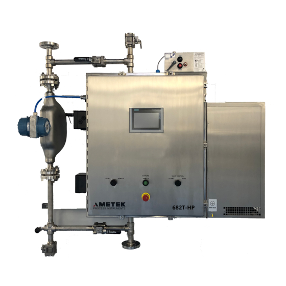
Chapter 1: Introduction, Page 7 1.4.1 XRT/XRA Analyzer DETECTOR X-RAY TUBE HEAD FLOW CELL The XRT/XRA Analyzer components consist of the Flow Cell, X-ray Tube Head, Detector Head, and related electronics. The signal from the Detector Head is fed to the Controller where it is corrected for density and applied in the calibration equation to yield the correct result. -
Page 15: Controller
Chapter 1: Introduction, Page 8 1.4.2 Controller The Controller components consist of the PLC and Touch Screen Display. The Controller performs three major functions: The first function is to monitor for error conditions. These conditions can include low purge pressure, piping leaks inside the sampler enclosure, communication failures, density errors, and temperatures outside the set limits. -
Page 16: Densitometer (Optional)
Chapter 1: Introduction, Page 9 1.4.3 Densitometer (Optional) The Densitometer components consist of the in-line density meter and processor that calculates the liquid density and feeds that signal to the Controller. The liquid density meter uses the spring mass principle for measuring fluid density. A portion of the measurement tube is energized to vibrate at its natural resonant frequency by using an electrical feedback driving system. -
Page 17: Installation
Chapter 2: Installation, Page 10 2 INSTALLATION This Section describes requirements for receiving and installing the analyzer. Site requirements consist of selecting the proper location and preparing it for process access, plant services (power, air, etc.), and suitable environmental conditions. Installer must confirm that the installation and process conditions, as well as the specifications in Section 8 are reviewed to determine that the installation is appropriate with the classified hazardous area. -
Page 18: Utility Requirements
Chapter 2: Installation, Page 11 Utility Requirements 2.3.1 Gas Supply Specifications Purge air (or protective gas) is connected to a 3/8” NPT entry at the purge controller. Refer to the Customer Drawings Except for cylinder-supplied gases, the point at which the protective gas enters the supply duct(s) should be situated in a non-hazardous area. -
Page 19: Electrical
Chapter 2: Installation, Page 12 2.3.2 Electrical The incoming AC utilized for all analyzers should be “clean” AC, that is, AC with no transient voltages on the line. No voltage dropout 10% below nominal and no voltage spikes 10% above nominal VAC. -
Page 20: Signal Connections
Chapter 2: Installation, Page 13 2.3.3 Signal Connections Instrument signals can be connected through 3/4” conduit hubs. Refer to the Custoemr Drawings and Wiring Diagrams supplied with your analyzer for connection details. Signal cables need to be connected to the analyzer through cable glands or conduit hubs. The cables and fittings must be rated for the environment for which the analyzer is intended. -
Page 21: Process Connections
Chapter 2: Installation, Page 14 2.3.4 Process Connections The process is connected through 600# ANSI RF flanges (other sizes available by request) at the top and bottom of the analyzer. The process flow inlet should be at the bottom of the analyzer with the outlet at the top. This prevents entrapment of any bubbles in the sample cell of the analyzer. -
Page 22: Purge Startup Procedure
Chapter 2: Installation, Page 15 Purge Startup Procedure The AMETEK ASOMA Model 682T-HP, ATEX Zone 2 configuration uses an Expo Model 07/ZLC/bp/IS purge unit to achieve enclosure protection. While this system does not automatically control power to the analyzer (as with an X-purge system), it will trigger an alarm and alert the user upon loss of protective pressure. -
Page 23: Operation
The Touch Panel Display will load the Main Screen after about 50 seconds. The 682T-HP is shipped from the factory with an example calibration installed in CalSet0 so you can test analyzer operations immediately. There is no guarantee that this calibration will provide the best results for your application. -
Page 24: Run Conditions
Chapter 3: Operation, Page 17 3.1.1 Run Conditions Note that a special power failure recovery feature of the system will cause the analyzer to start in the same state as when power was turned off. The following conditions determine whether the analyzer will start to RUN or be stopped when power is turned on: The system will RUN (start repeat analysis) if one of the following is true (assume power is on and no alarms are active):... - Page 25 Chapter 3: Operation, Page 18 M o d e l 6 8 2 T - H P U S E R M A N U A L A T E X Z o n e 2...
-
Page 26: Normal Start
Chapter 3: Operation, Page 19 Normal Start Check that the Status shows READY, then press the RUN button on the Touch Screen if the door control switch is in the LOCAL position. Alternatively, move the door control switch to the REMOTE position and wait for the remote run signal to start the analyzer. -
Page 27: Emergency Shut Down
Chapter 3: Operation, Page 20 Emergency Shut Down Note any error messages on the system display if possible. Turn the switch on the door to “OFF” to interrupt power to the entire unit. Cold Start Safety First Follow appropriate safety procedures before applying power to the instrument. -
Page 28: Password Screen
Chapter 3: Operation, Page 21 Set the Count Time and Pause A short count time makes the update more frequent but loses some precision. A long count time makes the result more precise but does not update as frequently. Set the Pause according to how much delay you want after each analysis before the start of the next analysis. - Page 29 Ametek Administrator (Level 9) There is also a factory password (Zadmin - Level 9) in case the passwords are lost. Contact AMETEK if you need the factory password. Passwords are only active for a configurable number of minutes. After the configured time has expired, the password level is set to 0 and the user can only inspect parameters until the appropriate password is entered again.
-
Page 30: Calibration Selection
3.5.2 Calibration Selection This 682T-HP Series On-line analyzer has four different calibration sets that can store calibrations for different applications. To change calibrations, select the CAL SET from the drop down menu in the first menu screen. Access is allowed for Operator2 (Level 2) or higher password. -
Page 31: Calibration Method Verification
Chapter 3: Operation, Page 24 3.5.3 Calibration Method Verification Most calibrations will have the fit calculated with the Exponent Method to correct for density changes. If enough samples of different densities are available, the Alpha Coefficient Method may be used to correct for density changes. -
Page 32: Modifications To Main Screen
Chapter 3: Operation, Page 25 If you want to unlock a CalSet to change the Calibration Method, view the CAL Screen and touch the SLOPE field of the desired CalSet. Do not change the slope, but simply press ENTER when the numeric touch pad appears. -
Page 33: Density Units
Chapter 3: Operation, Page 26 3.6.2 Density Units You may change the density units displayed on the Main Screen to any of the following: gm/cc kg/cuM lb/cuft lb/gal Ref@15C Select the density units you desire from the drop down box. Please be aware that the density on the Main Screen will be displayed in the units you select but the 4-20mA density output and density alarm levels and density units used in calculating the result remain set in gm/cc. -
Page 34: Zoom Screen
Chapter 3: Operation, Page 27 3.6.3 Zoom Screen A magnified screen with just the sulfur and density can be selected from a button on the main screen or set to automatically display when the Local/Remote door switch is turned to Remote (refer to section 6.5 Configure Warning for details). -
Page 35: Trend
Main Screen. Verification Utility The AMETEK ASOMA Model 682T-HP analyzer contains a utility for internal verification of the measurement system. This utility may be used to verify that the detector and X-ray tube yield the same results as when the system was last calibrated. - Page 36 Chapter 3: Operation, Page 29 3. Follow appropriate safety procedures to drain the fluid remaining in the analyzer. Take care when opening the manual Drain and Vent valves as the analyzer may contain hot process fluid under pressure. Open both the manual Drain and manual Vent valves to drain the system.
- Page 37 Chapter 3: Operation, Page 30 verification. If you need to abort the verification, press the “BUSY” button on this screen or press the Capture button on the front door. 6. When the system has finished the verification procedure, the screen will display the results in the boxes labeled “CntsPerSec-P1”...
-
Page 38: X-Ray Warning Light
Chapter 3: Operation, Page 31 X-ray Warning Light When an analysis is underway, the red light on the XRT/XRA Head will glow. This indicates that the X-ray Tube is on and that it is NOT safe to swing the XRT/XRA Head out. An interlock is provided to shut off X-rays if the XRT/XRA Head is removed from the flow cell. -
Page 39: Calibration
Chapter 4: Calibration, Page 32 ALIBRATION This 682T-HP Series On-line analyzer has been designed for the analysis of sulfur in oil. Samples with known sulfur content will need to be presented to the analyzer before meaningful results can be achieved. -
Page 40: Sample Presentation
Chapter 4: Calibration, Page 33 application. Use the example records to try out the various features of your analyzer. CalSet2 and CalSet3 contain blank records as shipped from the factory for those that desire to start from scratch. Sample Presentation It is recommended that new calibrations be done under conditions as close as possible as those expected during operation. -
Page 41: Capture Procedure - Using Pushbutton Control
Chapter 4: Calibration, Page 34 If the pipe arrangement s not the same as pictured, remember to also drain the density meter. The system will warn that the density is low and X-rays will be turned off. This is desirable since the X-rays would temporarily saturate the detector if they were transmitted through the empty flow cell. - Page 42 Chapter 4: Calibration, Page 35 into a Calibration Set when assays have been performed on captured samples. The Capture Buffer will hold 16 samples in a revolving sequence. The Buffer Record number is incremented by 1 each time the Capture button is pushed.
-
Page 43: Modifying Sample Data
Chapter 4: Calibration, Page 36 4.3.1 Modifying Sample Data You may want to add or change the sample data after the original calibration to improve the fit. 1. Turn the Local/Remote Switch on the front door to the LOCAL position and select the desired CAL SET from the drop down menu on the Main screen. - Page 44 Chapter 4: Calibration, Page 37 6. Select the record to write/overwrite. There are 8 calibration records available for every CalSet. Make sure the CalSet number displayed is for the CalSet you wish to modify! Access is allowed for Operator6 (Level 6) or higher password. 7.
-
Page 45: Changing The Calibration Method
Chapter 4: Calibration, Page 38 4.3.2 Changing the Calibration Method You may want to change the Calibration Method after the original calibration to improve the fit. A discussion of the difference between the Calibration Methods (Exponent or Alpha or Hyperbolic) is given in section 4.5 Calibration Fit. - Page 46 Chapter 4: Calibration, Page 39 and observing the Flow Cell temperature. While at the UTIL screen, set the counting time that will be used in running the captured analyses. 2. From the Main screen select the desired CalSet from the pull down menu. Then press the CAL button. Note that your selected CalSet is shown in the “Selected Column”.
-
Page 47: Calibration Fit
Chapter 4: Calibration, Page 40 9. Notice the button becomes highlighted and flashes “BUSY”. When the button goes back to showing “Capture”, the procedure is complete. 10. To inspect the results of the capture, select another record then come back to this record. This will cause the data to be refreshed. -
Page 48: Exponent Method
Chapter 4: Calibration, Page 41 You have a choice of methods for density correction – Exponent or Alpha or Hyperbolic. Each method can produce equally good fits, but each has advantages and disadvantages. 4.5.1 Exponent method The Exponent method can be used with at least 3 samples and does not need density variation in the samples to produce a good fit. -
Page 49: Alpha Method
Chapter 4: Calibration, Page 42 DENSITY is in gm/cc The CPS variable is divided by 100 to increase the number of significant digits that are displayed for the slope in the Calibration Coefficient Screen. 4.5.2 Alpha method The Alpha method requires at least 4 samples with varying densities. There is no need to hunt for the best Alpha coefficient because the calculation is done with the best Alpha automatically. -
Page 50: Hyperbolic Method
Chapter 4: Calibration, Page 43 The equation for a calibration fit with Alpha density correction is given as: % S = SLOPE*(CPS/100)*(1+ALPHA*DENSITY)+OFFSET CPS = Counts Per Second DENSITY is in gm/cc The CPS variable is divided by 100 to increase the number of significant digits that are displayed in the Calibration Coefficient Screen. -
Page 51: Calibration Errors
Chapter 4: Calibration, Page 44 The equation for a calibration fit with Hyperbolic correction is given as: % S = [SLOPE*(CPS/100)*DENS^EXP+OFFSET]/[1+CURVATURE*(CPS/100)*DENS^EXP] CPS = Counts Per Second DENS = DENSITY is in gm/cc EXP = Exponent The CPS variable is divided by 100 to increase the number of significant digits that are displayed for the slope in the Calibration Coefficient Screen. -
Page 52: Counting Statistics
Thus at best, it can be expected that 68% of the measurements of a peak will come within this calculated one-sigma deviation from a mean value. AMETEK ASOMA instrumentation can perform to this theoretical best precision limit for many applications. For most applications, however, some error due to instrument precision and sample presentation is added to the error due to the counting statistics. - Page 53 Chapter 4: Calibration, Page 46 EXAMPLE – Illustrating the effect of Count Time on observed precision using the equation from the example calibration fit with the exponent method (section 4.5.1 Exponent method): 1.5% S = 20674 CPS CPS 1 sigma Seconds Count Time % Expected Standard Deviation 143.7846 0.0334 71.89228...
-
Page 54: Hardware Details
Chapter 5: Hardware Details, Page 47 ARDWARE ETAILS Power Supplies A small rail mounted power supply provides 24 volts DC to the XTR/XRA Head and Detector electronics and the Densitometer. The PLC contains its own internal DC power supply to provide 24 volts for sensors and relays connected to the I/O. Output voltage DC 24V ... -
Page 55: Terminal Blocks
Chapter 5: Hardware Details, Page 48 is provided via a leakage compensation valve so that it just compensates for any leakage from the pressurized enclosure in addition to maintaining its pressurization. Purge Medium:- Compressed Air. Clean, dry, free of flammable gasses. Supply Pressure:- 60 –... - Page 56 Chapter 5: Hardware Details, Page 49 M o d e l 6 8 2 T - H P U S E R M A N U A L A T E X Z o n e 2...
-
Page 57: Leak Sensor
A capacitive sensor is provided that can be activated by any dense object such as metal or liquids. It will be adjusted by AMETEK prior to installation. Should readjustment be necessary, use the small adjustment screw on the top of the sensor. A good rule of thumb... -
Page 58: Ac Line Filter
Chapter 5: Hardware Details, Page 51 AC Line Filter On the lower left side of the controller electronics panel is an AC line filter that prevents interference due to inductive spikes in the line current. Head Mounting Plate The XRT/XRA Head and Detector are clamped to the flow cell by a hinged mounting plate assembly. -
Page 59: Fan
Chapter 5: Hardware Details, Page 52 Your instrument has a rhodium (Rh) target X-ray tube. The maximum voltage, also known as kilovolts peak (kVp), is 30 kilovolts (kV). The maximum current is 1000 microAmps (uA). The maximum tube output is 4 watts. The maximum output may limit the available current at higher voltages. -
Page 60: Flow Cell Window
Chapter 5: Hardware Details, Page 53 5.12 Flow Cell Window The Flow Cell Window is designed to be resistant to fouling or wax buildup. A more detailed description of the window can be found in Section 10.1.3 Flow Cell Window Assembly. -
Page 61: Heater (Optional)
Chapter 5: Hardware Details, Page 54 5.14 Heater (Optional) A heater may be supplied inside the enclosure. Please refer to the manual supplied with the heater for operation details. The heater is nominally set to control the cabinet temperature above 70° F (21°C). 5.15 Touch Panel The Touch Panel Display is a Siemens TP177B monochrome touch panel mounted on the front door of the analyzer. - Page 62 Chapter 5: Hardware Details, Page 55 Instructions for recalibrating the touch sensitivity of the panel are copied here for convenience. 1. Cycle the power and when the “Loader” window comes up, press the Control Panel button. 2. When the Control Panel appears, double tap the OP Display Properties icon. 3.
-
Page 63: Plc
Chapter 5: Hardware Details, Page 56 4. Tap the Recalibrate button and follow the directions to recalibrate the touch sensitivity of the display screen. 5. Close each window with the X box in the upper right corner until you return to the Loader Window. -
Page 64: Manual Valves
Chapter 5: Hardware Details, Page 57 Carefully re-insert the battery board into the connector on the PLC, and replace the terminal block covers. 5.17 Manual Valves Manual valves are included with the system to ease the introduction and draining of samples. -
Page 65: Intrinsically Safe Switching Amplifiers
Chapter 5: Hardware Details, Page 58 5.18 Intrinsically Safe Switching Amplifiers Several types of intrinsically safe switching amplifiers may be provided to safely connect signals from a hazardous location to the analyzer. Please follow manufacturer’s recommendations for connecting electrical circuits to these devices. The manufacturer’s recommendations are included with the OEM information below: Analog outputs, DP-0095: M o d e l 6 8 2 T - H P U S E R M A N U A L A T E X Z o n e 2... - Page 66 Chapter 5: Hardware Details, Page 59 M o d e l 6 8 2 T - H P U S E R M A N U A L A T E X Z o n e 2...
- Page 67 Chapter 5: Hardware Details, Page 60 M o d e l 6 8 2 T - H P U S E R M A N U A L A T E X Z o n e 2...
- Page 68 Chapter 5: Hardware Details, Page 61 Digital outputs, DP-0102: M o d e l 6 8 2 T - H P U S E R M A N U A L A T E X Z o n e 2...
- Page 69 Chapter 5: Hardware Details, Page 62 Digital inputs, DP-0094: M o d e l 6 8 2 T - H P U S E R M A N U A L A T E X Z o n e 2...
- Page 70 Chapter 5: Hardware Details, Page 63 M o d e l 6 8 2 T - H P U S E R M A N U A L A T E X Z o n e 2...
- Page 71 Chapter 5: Hardware Details, Page 64 RS485 isolator, DP-0099: M o d e l 6 8 2 T - H P U S E R M A N U A L A T E X Z o n e 2...
- Page 72 Chapter 5: Hardware Details, Page 65 M o d e l 6 8 2 T - H P U S E R M A N U A L A T E X Z o n e 2...
- Page 73 Chapter 5: Hardware Details, Page 66 Default DIP switch settings for Model D1061S: SW1-1 ON SW2-1 OFF SW3-1 OFF 250Ω between A- and B+ Hazardous Area SW1-2 ON SW2-2 OFF SW3-2 OFF RS485 Safe Area, No Termination Resistor SW1-3 ON SW2-3 ON SW3-3 ON Unconnected Pin 6 SUB D Connector...
- Page 74 Chapter 5: Hardware Details, Page 67 DIP switch settings for Modbus RTU: SW1-1 OFF SW2-1 OFF SW3-1 OFF No Termination Resister for Hazardous Area SW1-2 OFF SW2-2 OFF SW3-2 OFF RS485 Safe Area, No Termination Resistor SW1-3 ON SW2-3 ON SW3-3 ON Unconnected Pin 6 SUB D Connector SW1-4 ON...
- Page 75 Chapter 5: Hardware Details, Page 68 M o d e l 6 8 2 T - H P U S E R M A N U A L A T E X Z o n e 2...
- Page 76 Chapter 5: Hardware Details, Page 69 M o d e l 6 8 2 T - H P U S E R M A N U A L A T E X Z o n e 2...
-
Page 77: Utility Screen
Chapter 6: Utility Screen, Page 70 TILITY CREEN The UTIL button on the Main Screen provides access to the Utility Screen. The Count Time, Pause, Calibration Method and Analysis Mode are displayed on this screen. You may also view the monitored temperatures for the XRA/XRT Head, Flow Cell, and Cabinet by pressing the Temperature button. -
Page 78: Remote Count Time And Acquisition Delay
Chapter 6: Utility Screen, Page 71 If you want to directly control the valves for testing purposes, you may change the control to MANUAL and open and close the inlet and outlet valves as desired. Note that the valves will not open if the Valve Control Switch on the door is in the CLOSE position. -
Page 79: X-Ray Enable
Chapter 6: Utility Screen, Page 72 To change the configured Count Time, tap the field for the desired bit pattern and enter the new value on the pop up numeric pad. Valid Count Times are in the range of 1 to 320 seconds. -
Page 80: Password Maintenance
Chapter 6: Utility Screen, Page 73 password. The warning light on the X-ray Head should turn off when X-rays are disabled. The warning light is in series with the X-ray relay, so no X-rays should be generated when this light is off. This is a toggle button, so you may enable the X-rays by pressing the button again. -
Page 81: Logout
< 45°C X-ray Tube < 50°C Flow Cell < 260°C (Contact AMETEK if higher temperatures are expected) The Density warning limit is a range below 0.6 and above 1.2 gm/cc. Note that the units for the density range are always in gm/cc regardless of the units selected for display on the Main Screen. -
Page 82: Set Plc Clock
Chapter 6: Utility Screen, Page 75 remain ON if the density is between the lower and upper warning limit or the Low Density X-ray Disable button is DISABLED. All the warnings will default to ENABLED if the power is cycled. The Auto-Zoom button will cause the main screen to switch to a magnified display of the sulfur and density results automatically when the Local/Remote switch is in the Remote position. -
Page 83: Setup 4-20Ma Outputs
Chapter 6: Utility Screen, Page 76 Setup 4-20mA Outputs The system will output a signal proportional to the result of the sulfur measurement and the density at the end of every analysis. These outputs can be scaled through the UTIL screen by pressing the SetUp 4_20 button. -
Page 84: Setup Bounds
Chapter 6: Utility Screen, Page 77 In the event that the measured value is outside the range specified, the output involved will read 4mA or 20mA, depending on whether the measurement is below the minimum or above the maximum specified. Values between the 4 and 20 mA values will be reported linearly. -
Page 85: Density Update
Chapter 6: Utility Screen, Page 78 6.10 Density Update The Utility Screen contains a toggle button to stop updating the density for troubleshooting purposes. Access is allowed for Operator6 (Level 6) or higher password. Press the button until it displays NODUD to stop updating the density. This will cause the last measured density to be held as constant. -
Page 86: User Corrections
Chapter 6: Utility Screen, Page 79 6.13 User Corrections User Corrections may be applied after the result calculated by the calibration. The correction is applied as follows: User Corrected Result = Calibrated Result * User Multiplier + User Offset. User Corrections are calculated from the results of the analyzer compared to lab results on the same samples over a period of time. -
Page 87: Density Corrections
Chapter 6: Utility Screen, Page 80 If you no longer need a User Correction, you may disable the correction by touching the ENABLED field for the appropriate CalSet until it displays “NO”, then press the APPLY button. 6.14 Density Corrections Density Corrections may be made in the same manner as User Corrections. -
Page 88: Transfer Data
Chapter 6: Utility Screen, Page 81 Press the Setup Port 0 button to view or make changes to the RS-485 port. Please refer to Section #9 Additional Features for setup instructions. 6.16 Transfer Data Data may be exported to a Multi Media Card (MMC) for added diagnostic capabilities. A MMC needs to be installed to store the data. - Page 89 Chapter 6: Utility Screen, Page 82 Select the FILENAME field and enter your desired file name. The FILENAME can be up to 8 characters in length with no spaces or non-alphanumeric characters. For example “myDATA” is a valid FILENAME. The FILE NUMBER can be any number between 000 and 999.
-
Page 90: Temperatures
Chapter 6: Utility Screen, Page 83 measurements will be written to the file “\LOG\myDATA_005.csv”. The file names will increment until the measurements stop or the FILE NUMBER reaches “999”. When the MMC is read, there may be a significant number of files in the “LOG” folder or directory that represent one “log session”... - Page 91 Chapter 6: Utility Screen, Page 84 The Cabinet, X-ray Tube, and Flow Cell temperatures are monitored by default. An external temperature may be displayed from a customer supplied 4-20mA signal if desired. The external temperature may be used instead of the Flow Cell temperature to calculate the reference density correction by pressing the button next to “RTD Tp for Ref Dens Correction”...
-
Page 92: Alarms & I/O Configuration
Chapter 7: Alarms & I/O Configuration, Page 85 & I/O C LARMS ONFIGURATION General Alarm, Error Messages The general alarm is a dry contact that opens when power is off or an alarm condition has been detected. During normal operation the general alarm is closed. The following conditions can cause the general alarm contact to open when power is on: 1. -
Page 93: Leak In Cabinet
3276.7°C. Check the PLC thermocouple module. Blinking red lights on this module indicate broken thermocouple connections. If all temperatures seem normal except for the XRA/XRT Head, contact AMETEK for technical assistance. 7.1.3 No X-rays/No Counts If there is a problem with the X-ray generation or detection, the system display will warn “No X-rays”... -
Page 94: Purge Alarm
Make sure the cable from the Touch Panel Display is connected to the correct port of the PLC. Check for any loose connections and try cycling power. If this fails, you may need to reload the software. Contact the AMETEK service department for assistance. -
Page 95: Digital Outputs
Chapter 7: Alarms & I/O Configuration, Page 88 Please refer to section 6.7 Setup 4-20mA Outputs for setup instructions for these outputs. The loop resistance for the 4-20mA outputs should not exceed 275 ohms. These outputs have a common ground with the analyzer. An isolated analog output option is available if desired. - Page 96 Chapter 7: Alarms & I/O Configuration, Page 89 Several digital inputs are available to assist in remote operation of the analyzer. A common ground is provided to ensure signal compatibility between the remote device and the analyzer. Each input will be set when +15 to +30 VDC is applied to the terminal and unset when 0 to +5 VDC is applied.
-
Page 97: Specifications & Certification
Chapter 9: Additional Features, Page 90 & C PECIFICATIONS ERTIFICATION Specifications When the optional heater is installed in the enclosure, the following additional marking is included: M o d e l 6 8 2 T - H P U S E R M A N U A L A T E X Z o n e 2... -
Page 98: Additional Features
Chapter 9: Additional Features, Page 91 DDITIONAL EATURES MODBUS Output and Control Option Modbus output and control is optionally available for the AMETEK ASOMA Model 682T-HP. The Modbus output and control option may be selected from the Port Setup Screen. 9.1.1 MODBUS Protocol... - Page 99 Word is Big Endian (MSB first). Word size & content: Floating point values are single precision IEEE 754 standard. Floating point values require 2 contiguous Word's. 682T-HP MODBUS WORD ASSIGNMENTS Address Description Value O40001 Status Word:RUN BIT = 1 when system is in RUN...
-
Page 100: Modbus Initialization
Chapter 9: Additional Features, Page 93 O40002 Control Word:RESERVED BIT = reserved for future use 0x1000 O40002 Control Word:RESERVED BIT = reserved for future use 0x2000 O40002 Control Word:RESERVED BIT = reserved for future use 0x4000 O40002 Control Word:RESERVED BIT = reserved for future use 0x8000 O40003- 040004... -
Page 101: Modbus Error Codes
Chapter 9: Additional Features, Page 94 4. Set the FP-PLC button to swap the floating point word order. 5. Press the Modbus or Wired button to set the Remote Method to control by Modbus or by discrete wires. 6. Connect to the Modbus Master and press the UpDate button. Verify that the data is available at the Modbus Master. -
Page 102: Remote Method
Chapter 9: Additional Features, Page 95 Example output from an analysis run: CalSet1 (%S) CNTS/SEC DENSITY DenCORR Ctsec Tcell Tcab Ttube 01/27/05 0.09952 26697.76 0.90113 0.90113 100.00 29.2 28.7 34.2 15:02:06 0.09399 26721.44 0.90113 0.90113 100.00 29.3 28.7 34.3 15:03:46 0.09436 26719.84 0.90113... -
Page 103: Maintenance & Troubleshooting
Chapter 10: Maintenance & Troubleshooting, Page 96 10 M & T AINTENANCE ROUBLESHOOTING 10.1 Routine Service The instrument is inherently a low service machine. Several of the simple service routines are described below. Whenever you work on the machine be sure the power is off before moving the X-ray tube or detector. - Page 104 Chapter 10: Maintenance & Troubleshooting, Page 97 Press the STOP button on the Touch Screen Display to stop automatic anal- ysis. Turn power off and follow appropriate safety procedures before opening the electronics enclosure. Unfasten the head mounting plate from the flow cell and swing out the XRT Head.
-
Page 105: Flow Cell Window Assembly
This analyzer is equipped with special flow cell windows. They are made of 200 mil thick beryllium coated to eliminate corrosion. These windows should never need to be replaced. Please contact AMETEK if you have concerns regarding these windows. M o d e l 6 8 2 T - H P U S E R M A N U A L A T E X Z o n e 2... -
Page 106: Replacing Parts
A list of recommended spare parts can be found at the end of this chapter. Use only AMETEK approved components to repair the AMETEK analyzer. Warning: Substitution of non-approved components may impair the analyzer safety and suitability for areas classified as hazardous. -
Page 107: Updating The Tp-177B Software
Chapter 10: Maintenance & Troubleshooting, Page 100 internal load memory of the CPU. The RUN/STOP LED alternately flashes green and yellow to indicate that the program is being copied. When the RUN/STOP LED turns on (solid yellow) and the MAINT LED flashes, the copy process has finished. You can then remove the memory card. - Page 108 Chapter 10: Maintenance & Troubleshooting, Page 101 Select the Backup tab and press the Next button. Insert the SD card in the Data slot in back of the HMI. Do not insert in the System slot! The card should be oriented with the label to the right and the notch to the bottom when looking at the back of the HMI as pictured.
- Page 109 Chapter 10: Maintenance & Troubleshooting, Page 102 Select the row with the storage card when it appears in the window. Press the Next button. Previous backup files on the SD card (if any) will be displayed. Press the Backup button. M o d e l 6 8 2 T - H P U S E R M A N U A L A T E X Z o n e 2...
- Page 110 Chapter 10: Maintenance & Troubleshooting, Page 103 Select Complete backup with licenses. The file name is normally the current date. You can change this if desired or leave it alone. Press the Create button. Wait about 5 minutes. Press OK when the Backup success window is displayed. Press the X in the upper right to return to the Control Panel.
- Page 111 Chapter 10: Maintenance & Troubleshooting, Page 104 press Start for normal operation. The SD card can remain in the Data slot or be removed if desired. Restore: Follow the initial steps of the Backup procedure except select the Restore tab instead of Backup.
- Page 112 Chapter 10: Maintenance & Troubleshooting, Page 105 Wait for transfer about 3 minutes. Don’t worry when the screen goes blank. A normal boot-up follows shortly after. If you watch carefully, you will catch the restore success message just before the screen goes blank.
- Page 113 Houston, TX 77041 Telephone: 713 466-4900 Fax: 713 849-1924 Email: asoma.support@ametek.com AMETEK Process & Analytical Instruments Division 150 Freeport Road Pittsburgh, PA USA 15238 Telephone: (412) 828-9040 Fax: (412) 826-0399 M o d e l 6 8 2 T - H P U S E R M A N U A L A T E X Z o n e 2...
-
Page 114: Warranty
Appendix A: Warranty, Page a WARRANTY A. Seller warrants that Products manufactured by Seller, when delivered, shall be free from defects in material/workmanship. Seller's obligations under this warranty shall be limited exclusively to repairing or replacing, at Seller's option, any part of Products which, if properly installed, used and maintained, proved to have been defective in material or workmanship within 18 months from the date of shipment or 12 months from date of installation, whichever comes first. -
Page 115: Appendix B: Radiation Safety
If failure or damage occurs which could affect the shielding of the X-ray tube, the appropriate authorities (listed at the end of this section) and AMETEK Process Instruments should be notified immediately. If the instrument is seriously damaged such that the X-ray Head is no longer shielded, the instrument should be turned off until trained personnel can take corrective action. -
Page 116: Radiation Levels
The Model 682T-HP is designed to survive the dust and dirt encountered in industrial situations. The X- rays used by the Model 682T-HP to analyze a sample are of very low energy. When they are properly shielded to factory specifications, radiation exposure will be well below regulatory limits. - Page 117 Appendix B: Radiation Safety, Page d Radiation Survey AMETEK Model 682T-HP S/N _____________ Voltage 27 kV Current 75 A Number Reading (mR/hr) (5 cm from surface) < 0.1 Near Side of Head < 0.1 Top of Head < 0.1 Right Side of Head <...
-
Page 118: Regulatory Obligations
Instruments will provide you with the name and address of the agency you should contact, and will assist you with filling out such forms as they may require. The room or work area containing the Model 682T-HP must be posted with a sign or signs bearing the radiation symbol and the words, “Caution - X-ray Equipment”, or wording with a similar intent.
Need help?
Do you have a question about the 682T-HP and is the answer not in the manual?
Questions and answers