Table of Contents
Advertisement
Quick Links
Advertisement
Table of Contents

Related Manuals for Cascade TEK SVO-10-VC


Summary of Contents for Cascade TEK SVO-10-VC
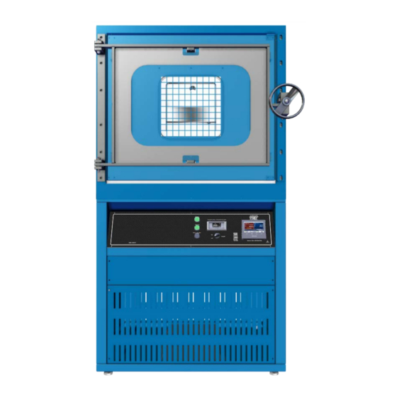
- Page 1 Vacuum Control Oven SVO-10-VC Installation and Operation Manual...
- Page 2 These ovens require permanent connect wiring (also known as hardwiring) to a power supply. Warning: This product contains chemicals, including triglycidyl isocyanurate, known to the State of California to cause cancer as well as birth defects or other reproductive harm. For more information, go to www.P65Warnings.ca.gov.
- Page 3 The Part ID denotes the build type of the model. The manufacturer periodically releases new build types incorporating new features and refinements of existing ones. This oven is manufactured for Cascade TEK by Sheldon Manufacturing, INC, an ISO9001-certified manufacturer. P a g e...
-
Page 4: Table Of Contents
TABLE OF CONTENTS MODEL CERTIFICATIONS............................7 Safety Certifications................................7 INTRODUCTION ..............................9 Read this Manual ..................................9 Safety Considerations and Requirements ........................9 Contacting Assistance ................................ 10 Manufacturing Warranty ..............................10 Engineering Improvements ............................... 10 Vacuum Pump Options ................................ 11 Compressed Air Supply Required ............................ - Page 5 Electrical Components ............................... 54 Storage ....................................54 UNIT SPECIFICATIONS ............................55 Weight ..................................... 55 Dimensions .................................... 55 Capacity ....................................55 Shelf Capacity by Weight ..............................56 Vacuum ....................................56 Temperature ..................................57 Power .......................................57 REPLACEMENT PARTS ............................59 P a g e...
- Page 6 TABLE OF CONTENTS P a g e...
-
Page 7: Model Certifications
MODEL CERTIFICATIONS Model Certification and Compliance Statements AFETY ERTIFICATIONS 61010 Safety Certified Electrical, mechanical, and fire hazards The unit models in this manual are CUE listed by TÜV SÜD America as vacuum ovens for professional, industrial, or educational use in conditions in which no flammable, volatile, or combustible materials are being heated and the unit is being operated under an environmental air pressure range of 22.14 –... - Page 8 CERTIFICATIONS P a g e...
-
Page 9: Introduction
INTRODUCTION Thank you for purchasing a Cascade TEK oven. We know you have many choices in today’s competitive marketplace when it comes to constant temperature equipment. We appreciate you choosing ours. We stand behind our products and will be here if you need us. -
Page 10: Contacting Assistance
NGINEERING MPROVEMENTS Cascade TEK continually improves its products. As a result, engineering changes and improvements are made from time to time. Therefore, some changes, modifications, and improvements may not be covered in this manual. If your unit’s operating characteristics or appearance differs from those described in this manual, please contact your Cascade TEK dealer or customer service representative for assistance. -
Page 11: Vacuum Pump Options
INTRODUCTION ACUUM PTIONS SVO-10-VC ovens can be ordered with one of several vacuum pump types installed inside the oven utility cabinet. These pumps vary in pump down flow rates and suitability for different baking applications. Refer to the vacuum pump manufacturer manual included with the oven for specifications and compatibility with applications. -
Page 12: Gasket Chemical Vulnerabilities
INTRODUCTION ASKET HEMICAL ULNERABILITIES The oven comes with a Viton® gasket built into the oven door. The gasket must seal against the un- nicked contact surface on the oven body in order for the oven chamber to hold vacuum. The gasket is a low wear, long-duration component that is rated to 220°C and typically replaced only during scheduled services on the oven. -
Page 13: Receiving Your Oven
6. Verify the correct number of accessory items has been included. 7. Carefully check all packaging for accessories before discarding. Included Accessories: SVO-10-VC Leveling Feet Shelf Shelf Clip... -
Page 14: Orientation Images
RECEIVING RIENTATION MAGES SVO-10-VC Shelf Door Latch Shelf Standard Mounting Rail Temperature Probe (Below Shelf) Control Panel Door Hasp Door Gasket Oven Chamber Door Pump Cabinet 14 | P a g e... - Page 15 RECEIVING Back of Oven – SVO-10-VC Backfill Valve Compressed Air KF-25 Auxiliary Access Port Port ¼ inch (6.35 mm) Push Fitting Backfill Intake Port 3/8 inch (9.5 mm) KF-40 Automated Vacuum Port Hardwire Power Feed Vacuum Exhaust Tubing (standard pump units)
-
Page 16: Dimension Visuals
RECEIVING IMENSION ISUALS SVO-10-VC Depth: 46.8 inches (1189 mm) Height: 70.4 inches (1787 mm) Exterior Width: 38.7 inches (983 mm) Chamber Height: 24.5 inches (622 mm) Chamber Depth: 26.0 inches (660 mm) Interior Shelf Chamber Width: 28.8 inches Depth:25.0 inches... -
Page 17: Record Data Plate Information
RECEIVING ECORD LATE NFORMATION Record the unit model number, serial number, part number, and part ID below for future reference. Customer Support needs this information to provide accurate help during support calls and emails. The data plate is located on the back, right side of the oven, above the compressed air inlet •... - Page 18 RECEIVING 18 | P a g e...
-
Page 19: Installation
INSTALLATION OWER ARDWIRING EQUIREMENT The oven requires permanent connect wiring (commonly known as hardwiring). Wiring to the power source must be performed by a qualified electrical technician. All other Installation steps may be performed by the operator. NSTALLATION ROCEDURES HECKLIST For installing the unit in a new workspace location. -
Page 20: Required Ambient Conditions
INSTALLATION EQUIRED MBIENT ONDITIONS This oven is built for use indoors, at room temperatures between 15°C and 40°C (59°F and 104°F), at no greater than 80% Relative Humidity (at 25°C / 77°F). Operating outside these conditions may adversely affect the oven temperature performance. When selecting a location to install the unit, consider all environmental conditions that can adversely impact its temperature performance. -
Page 21: Power Source Requirements
The unit is intended for 50/60 Hz applications at the following amperage: • Model AC Voltage Amperage SVO-10-VC 220 – 240 The power source must be protective earth grounded and single phase. • The power source must conform to all national and local electrical codes. -
Page 22: Lifting And Handling
INSTALLATION IFTING AND ANDLING The oven is heavy. Use appropriate lifting devices that are sufficiently rated for these loads. Follow these guidelines when lifting the oven: Lift the oven only from its bottom surface. • Doors, handles, and knobs are not adequate for lifting or stabilization. •... -
Page 23: Disengage The Vacuum Pump Locks
INSTALLATION Note: The manufacturer recommends that this procedure be performed by a qualified electrical technician. The oven should remain disconnected from its power source throughout the procedure. ISENGAGE THE ACUUM OCKS The oven vacuum pump has four internal shipping locks on its base to cinch it to the floor of the electronics cabinet. -
Page 24: Installation Cleaning
INSTALLATION NSTALLATION LEANING The manufacturer recommends cleaning the shelving and oven chamber prior to installation of the shelving in the chamber. The unit was cleaned at the factory but may have been exposed to contaminants during shipping. Remove all wrappings and coverings from shelving prior to cleaning and installation. •... -
Page 25: Shelving Installation
INSTALLATION HELVING NSTALLATION To ensure accurate temperature measurement, one shelf bottom must be in close proximity to the oven temperature probe. This probe extends out from the chamber back wall. Do not place the shelf in direct contact with the probe. Shelf Probe Install 6 Shelf Clips... -
Page 26: Connect Gas Supplies
INSTALLATION ONNECT UPPLIES Optional: Connect equipment to the KF-25 auxiliary port. Comes with a blank and clamp. 1. Connect your compressed air supply to this ¼-inch (6.35 mm) push fitting. The oven requires 70 – 80 • psi of pressure delivered at this port to operate its pneumatic valves. -
Page 27: Vent The Pump Exhaust
INSTALLATION Note: Outgassed byproducts may be hazardous to or noxious for operating personnel. Vacuum pump exhaust should be vented to a location outside the workspace in a safe manner in accordance with all applicable laws, ordinances, and regulations. ENT THE XHAUST The oven comes with a vacuum pump installed in the electronics cabinet at the base of the oven. -
Page 28: Verify The Oven Chamber Is Empty
INSTALLATION ERIFY THE HAMBER IS MPTY Prior to placing the oven into operation, verify the oven chamber is clean and all shipping dunnage and any shelf wrappings have been removed. Failure to do so may result in damage to the oven chamber interior or vacuum pump. ARDWIRE THE VEN TO OWER... -
Page 29: Graphic Symbols
GRAPHIC SYMBOLS The oven is provided with graphic symbols on its exterior surfaces. These identify hazards and the functions of the adjustable components, as well as important notes in the user manual. Symbol Definition Consult the user manual Consulter le manuel d'utilisation AC Power Repère le courant alternatif Potential shock hazard... - Page 30 SYMBOLS 30 | P a g e...
-
Page 31: Control Overview
CONTROL OVERVIEW Control Panel Vacuum Gauge Display – Backfill Limit Shows the chamber pressure level in Torr and millitorr (mTorr). The gauge this display connects to measures the pressure of pure nitrogen (N ) and is used to control the automated backfill function. Backfilling is commonly done using N or other inert gases. - Page 32 CONTROLS Power Switch Controls all power to the oven and its systems. Main and Limit Controller – Homepage Home Returns the display to the homepage. Menu Accesses the password for unlocking the heating profile programming menu. Return Returns the display to the previous page or menu.
- Page 33 CONTROLS Oven Shelving Temperature Tab - Homepage The current oven chamber shelving temperature, 48.1°C A Constant Temperature Setpoint (SP) of 150.0°C entered on the setpoint button. Oven heating with 100% power (PWR) PV (Process Value): When atmosphere is present in the chamber, the Process Value shows •...
- Page 34 CONTROLS Note: Both vacuum functions can be manually turned on from the homepage by tapping the button or turned on as a heating profile step parameter. The button indicator disk changes from gray to green when turned on. Vacuum Control The Vacuum Control function dynamically adjusts the chamber vacuum valve to achieve and then maintain a pressure level between room atmosphere pressure and 1 Torr.
- Page 35 CONTROLS Right Arrow Tapping the arrow brings up the Oven Limit page. Oven Limit Page The Oven Limit (OTP) system sets an independent heating cutoff temperature to help safeguard the oven in the event of a hardware failure or external event. See the Oven Limit topic on page 39 for more information.
- Page 36 CONTROLS 36 | P a g e...
-
Page 37: Operation
OPERATION Safe operation of the oven is dependent on the actions and behavior of the oven operators. Operating personnel must read and understand the Operating Precautions in this section prior to operating the oven. The operators must follow these instructions to prevent injuries and to safeguard their health, environment, and the materials being treated in the oven, as well as to prevent damage to the oven. -
Page 38: Theory Of Operation
OPERATION HEORY OF PERATION Vacuum and Vacuum Automation Atmosphere is pumped out of the oven chamber through a pneumatic vacuum valve on the back of the oven and then exits through the roughing vacuum pump connected to the valve. The valve position is controlled by either the Full Vacuum or Vacuum Control functions. - Page 39 OPERATION Heating in a Vacuum In conventional ovens, powered elements transfer heat into the chamber air. The heated air then circulates by natural convection or blower fan action, surrounding the product on the shelves and gradually bringing it to temperature. In a vacuum oven, heat transfer takes place in part through infrared radiation.
-
Page 40: Put The Oven Into Operation
OPERATION UT THE VEN INTO PERATION Perform the following procedures and steps to put the unit into operation after installing it in a new workspace environment. Turn on the oven Optional: Back up the oven controller. The manufacturer recommends backing up your oven controller •... -
Page 41: Logging In And Out
Tap the Logout icon in the Main Menu • Confirm Logout • End of Procedure Changing the Password The default oven password is ctek. The password may be changed using Watlow Composer™ software. However, Cascade TEK cannot recover a lost password. 41 | P a g e... -
Page 42: File Export And Import
OPERATION Note: A USB must be inserted into the USB-A drive on the control panel next to the display screen to access the File Transfer menu. XPORT AND MPORT The manufacturer recommends exporting the controller software configuration when first putting the oven into use. -
Page 43: Set The Oven Limit (Otp) Temperature
OPERATION (OTP) T ET THE IMIT EMPERATURE Note: Test the oven limit system once per year for functionality. Set the oven limit threshold where the independent Temperature Limit circuitry cuts off heating of the oven chamber. Considerations when setting the oven limit cutoff: Set the limit prior to activating heating. -
Page 44: Latch The Oven Chamber Door
OPERATION ATCH THE HAMBER Ensure the oven door is securely latched before placing the chamber under vacuum. Position the door handle. Swing the handle wheel all the way to the left, until it is facing forward. • Secure the chamber door. Using one hand, turn the handle wheel clockwise (to the •... -
Page 45: Pump Down The Oven Chamber
OPERATION OWN THE HAMBER Note: Perform a Full Vacuum pump down of the chamber for at least 10 minutes when first putting the oven into operation in a new location to verify the vacuum supply system integrity. An operator must always be present to observe the vacuum gauge pressure display decreasing while the oven is drawing a vacuum to ensure the system is sealed. - Page 46 OPERATION Option 2 – Manual Vacuum Control Pumps down the oven chamber to a setpoint between room pressure and 1 Torr. 1. Enter a vacuum setpoint between 1 Torr and 760 Torr on the homepage vacuum tab. 2. The manufacturer strongly recommends entering an initial setpoint of at least 500 Torr to ensure the oven chamber seals completely.
- Page 47 OPERATION Option 3 – Profile Automation Note: Pump Start cannot be turned on automatically. An operator must always be present to turn on the vacuum pump and verify the oven chamber is sealed as the oven pumps down. The Vacuum Control or Full Vacuum functions may be set to automatically turn on as part of a heating profile.
-
Page 48: Backfill The Chamber
OPERATION ACKFILL THE HAMBER Atmosphere is restored to the chamber in two stages. Stage 1: Automatic Partial Backfill Two triggers cause the oven to close the vacuum valve and partly backfill the oven chamber to approximately 600 Torr. Manual Trigger When both vacuum functions are manually turned off. -
Page 49: Setting A Constant Temperature Setpoint
OPERATION Note: Heating to your baking application temperature with atmosphere in the chamber will result in a drop in temperature when the chamber is pumped down. It may also oxidize chamber surfaces. ETTING A ONSTANT EMPERATURE ETPOINT Enter 1. Tap the Setpoint button on the Homepage oven temp tab. 2. -
Page 50: Oven Limit Active
OPERATION IMIT CTIVE Limit activations serve as a persistent, protective interruption of heating in the oven chamber. Always identify and correct the cause of an oven limit activation before restoring heating. Oven Limit Heating Cutoff Active In this example, the chamber temperature Note: Tapping Clear or Dismiss on the Alert exceeds both the Oven Limit Setting and the Window does not end the Oven Limit. - Page 51 OPERATION Clearing an Active Limit Cutoff The oven shelving temperature must be below the Oven Limit setting before a Limit cutoff can be cleared (canceled). Alarm Message: This alert window appears the first time a button is Always identify and correct the cause of an Oven Limit tapped during a Limit cutoff.
-
Page 52: Data Ports
OPERATION ORTS Front of Unit Control Panel USB A The USB port located on the front control panel accesses the Main and High Limit controller and can be used for the following: Exporting and importing heating profiles from the controller •... -
Page 53: Operator Maintenance
OPERATOR MAINTENANCE Warning: Disconnect the unit from its power supply prior to maintenance or service. Avertissement: Avant d'effectuer toute maintenance ou entretien de cet appareil, débrancher le cordon secteur de la source d'alimentation. LEANING If a hazardous material or substance has spilled in the unit, immediately initiate your site Hazardous Material Spill Containment protocol. -
Page 54: Maintaining Atmospheric Integrity
MAINTENANCE AINTAINING TMOSPHERIC NTEGRITY Periodically, inspect the door latch, trim, catch, and gasket for signs of deterioration. Failure to maintain the integrity of the door system shortens the lifespan of the unit. ASKETS The door gasket is a low-wear item. It typically only needs to be replaced due to being cut or nicked. The risk of this type of damage can be significantly reduced by opening the door to 130°, keeping it well out of the way of shelves or sample trays being removed from or inserted into the chamber. -
Page 55: Unit Specifications
All indications are average values, typical for units produced in the series. We reserve the right to alter technical specifications at all times. EIGHT Model Shipping Weight SVO-10-VC 1634 lb / 741 kg IMENSIONS Inches Model Exterior W ×... -
Page 56: Shelf Capacity By Weight
EIGHT Model Per Shelf Maximum Total Load Max. No. Shelves SVO-10-VC 50.0 lb / 22.7 kg* 200.0 lb / 90.7 kg** 8 Shelves *50.0 lb / 22.7 kg with weight evenly distributed across the shelf. **200.0 lb / 90.7 kg total load in the chamber. Exceeding this limit risks damaging the chamber liner. -
Page 57: Temperature
SPECIFICATIONS EMPERATURE Range, Stability, and Uniformity Model Range Stability Uniformity SVO-10-VC Ambient +10° to 220°C ± 0.2°C @ All Temps ±6% of Setpoint OWER Model AC Voltage Amperage Frequency SVO-10-VC 220 – 240 50/60 Hz 57 | P a g e... - Page 58 SPECIFICATIONS 58 | P a g e...
-
Page 59: Replacement Parts
3450755 Ordering Parts and Consumables Parts may be ordered from Cascade TEK by calling 1-888-835-9250. Please have the model, part, and serial numbers, and Part ID of the unit ready, as Customer Support will need this information to match your unit to its correct part. - Page 60 Corporate Headquarters Cascade TEK Solutions, LLC 2010 Century Center Blvd, Suite 21 Irving, Texas 75062 support@cascadetek.com cascadetek.com 1-888-835-9250 1-971-371-4096...
Need help?
Do you have a question about the SVO-10-VC and is the answer not in the manual?
Questions and answers