Table of Contents
Advertisement
Quick Links
Advertisement
Table of Contents

Related Manuals for Cascade TEK SVO-5-T


Summary of Contents for Cascade TEK SVO-5-T
- Page 1 Turbo Vacuum Ovens SVO-5-T SVO-10-T Installation and Operation Manual...
- Page 2 Pictured on Front Cover, Left to Right: SVO-5-T, SVO-10-T These ovens require permanent connect wiring (also known as hardwiring) to a power supply. Warning: This product contains chemicals, including triglycidyl isocyanurate, known to the State of California to cause cancer as well as birth defects or other reproductive harm. For more information, go to www.P65Warnings.ca.gov.
- Page 3 CTVT1022-H CTVT522-H The Part ID denotes the build type of the model. Cascade TEK periodically releases new build types of these models incorporating new features and refinements of existing ones. These units are built for Cascade TEK by Sheldon Manufacturing, INC, an ISO-certified manufacturer.
-
Page 4: Table Of Contents
TABLE OF CONTENTS MODEL CERTIFICATIONS ............................7 Safety Certifications................................7 INTRODUCTION ................................ 9 Read this Manual ..................................9 Safety Considerations and Requirements ........................9 Contacting Assistance ................................ 10 Manufacturing Warranty ..............................10 Engineering Improvements..............................10 Roughing Vacuum Pump Options ............................ 11 Compressed Air Supply Required ............................ - Page 5 Maintaining Atmospheric Integrity ..........................58 Gaskets ....................................58 Electrical Components ............................... 58 Storage ....................................58 UNIT SPECIFICATIONS ............................59 Weight ..................................... 59 Dimensions .................................... 59 Capacity ....................................59 Shelf Capacity by Weight ..............................60 Vacuum ....................................60 Temperature ..................................60 Power .......................................
- Page 6 TABLE OF CONTENTS P a g e...
-
Page 7: Model Certifications
MODEL CERTIFICATIONS Model Certification and Compliance Statements AFETY ERTIFICATIONS 61010 Safety Certified Electrical, mechanical, and fire hazards The unit models in this manual are CUE listed by TÜV SÜD America as vacuum ovens for professional, industrial, or educational use in conditions in which no flammable, volatile, or combustible materials are being heated and the unit is being operated under an environmental air pressure range of 22.14 –... - Page 8 CERTIFICATIONS P a g e...
-
Page 9: Introduction
INTRODUCTION Thank you for purchasing a Cascade TEK oven. We know you have many choices in today’s competitive marketplace when it comes to constant temperature equipment. We appreciate you choosing ours. We stand behind our products and will be here if you need us. -
Page 10: Contacting Assistance
Therefore, some changes, modifications, and improvements may not be covered in this manual. If your unit’s operating characteristics or appearance differs from those described in this manual, please contact your Cascade TEK dealer or customer service representative for assistance. -
Page 11: Roughing Vacuum Pump Options
INTRODUCTION OUGHING ACUUM PTIONS The turbopump on the back of the oven operates in conjunction with a roughing pump in the oven pump cabinet. Both pumps are installed at the factory and come plumbed to the oven vacuum system. Refer to the pump manufacturer manuals shipped with the oven for specifications and compatibility with applications. -
Page 12: Gasket Chemical Vulnerabilities
INTRODUCTION ASKET HEMICAL ULNERABILITIES The oven comes with a Viton® gasket built into the oven door. The gasket must seal against the un- nicked contact surface on the oven body in order for the oven chamber to hold vacuum. The gasket is a low wear, long-duration component that is rated to 220°C and typically replaced only during scheduled services on the oven. -
Page 13: Receiving Your Oven
6. Verify the correct number of accessory items has been included. 7. Carefully check all packaging for accessories before discarding. Included Accessories: SVO-10-T Leveling Feet Shelf Shelf Clip SVO-5-T Leveling Feet Shelf Shelf Clip 13 | P a g e... -
Page 14: Orientation Images
RECEIVING RIENTATION MAGES SVO-10-T Door Gasket Door Hasp Door Latch Oven Chamber Door Shelf Turbopump Port Turbopump Monitor Roughing Pump (In the Cabinet) Temperature Sensor Probe (below shelf) Control Panel Electronics Cabinet 14 | P a g e... -
Page 15: Orientation Images
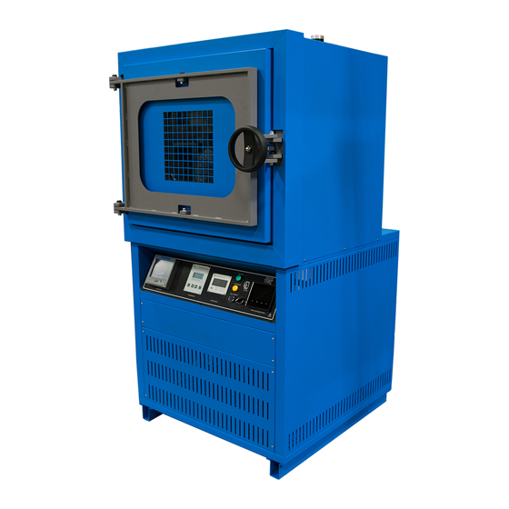
RECEIVING RIENTATION MAGES SVO-5-T Door Gasket Door Hasp Door Latch KF-25 Access Port Oven Chamber Door Turbopump Port Turbopump Monitor Shelf Roughing Pump (In the Cabinet) Control Panel Electronics Cabinet 15 | P a g e... - Page 16 RECEIVING Back of Oven Foreline Gauge Auxiliary Chamber Port (KF-25) Backfill Valve Compressed Air Port ¼” (6.35 mm) Push Fitting Turbopump Backfill Intake Port 3/8” (9.5 mm) Foreline Roughing Vacuum Valve Hardwire Power Feed (Shipping Cover Pictured) Vacuum Exhaust Tubing (standard pump units) 16 | P a g e...
-
Page 17: Dimension Visuals
RECEIVING IMENSION ISUALS SVO-10-T Height: 75.8 inches (1925 mm) Depth: 52.9 inches (1343 mm) Exterior Width: 38.7 inches (983 mm) Chamber Height: 24.5 inches (622 mm) Chamber Depth: 26.0 inches (660 mm) Interior Shelf Chamber Width: 28.8 inches Shelf Depth: 25.0 (730 mm) inches (635 mm) Shelf Width: 28.2 inches (718 mm) - Page 18 RECEIVING SVO-5-T Depth: 51.9 inches (1318 mm) Height: 69.2 inches (1758 mm) Exterior Width: 28.8 inches (732 mm) Chamber Depth: 26.0 inches (660 mm) Chamber Height: 18.0 inches (457 mm) Interior Shelf Chamber Width: 18.0 inches Shelf Depth:25.0 (457 mm) inches (635 mm) Shelf Width: 17.5 inches (444 mm)
-
Page 19: Record Data Plate Information
RECEIVING ECORD LATE NFORMATION The data plate contains the unit model number, serial number, part number, and part ID. Customer Support will need this information during any support call. Record it below for future reference. The data plate is located on the back, right side of the oven, above the compressed air inlet •... - Page 20 RECEIVING 20 | P a g e...
-
Page 21: Installation
INSTALLATION ARDWIRE EQUIREMENT The oven requires permanent connect wiring (commonly known as hardwiring). Wiring to the power source must be performed by a qualified electrical technician. All other installation steps may be performed by the operator. NSTALLATION ROCEDURES HECKLIST For installing the unit in a new workspace location. Pre-Installation ... -
Page 22: Required Ambient Conditions
12” (305 mm) Gas In Ports Door Swing 6” (152 mm) 6” (152 mm) SVO-5-T 24.8” (630 mm) SVO-10-T 34.7” (882 mm) Leave a 130° arc for the door swing. This allows large sample trays to be removed safely from the chamber without damaging the door seal or metal sealing surfaces. -
Page 23: Power Source Requirements
• Model AC Voltage Amperage SVO-10-T 220 – 240 SVO-5-T 220 – 240 The power source must be protective earth grounded and single phase. • The power source must conform to all national and local electrical codes. • The unit may be damaged if the supplied voltage varies by more than 10% from the data •... -
Page 24: Lifting And Handling
INSTALLATION IFTING AND ANDLING The oven is heavy. Use appropriate lifting devices that are sufficiently rated for these loads. Follow these guidelines when lifting the oven: Lift the oven only from its bottom surface. • Doors, handles, and knobs are not adequate for lifting or stabilization. •... -
Page 25: Disengage The Roughing Pump Locks
INSTALLATION Note: The manufacturer recommends that this procedure be performed by a qualified electrical technician. The oven should remain disconnected from its power source throughout the procedure. ISENGAGE THE OUGHING OCKS The oven roughing pump has four internal shipping locks on its base to cinch it to the floor of the electronics cabinet. -
Page 26: Installation Cleaning
INSTALLATION NSTALLATION LEANING The manufacturer recommends cleaning the shelving and oven chamber prior to installation of the shelving in the chamber. The unit was cleaned at the factory but may have been exposed to contaminants during shipping. Remove all wrappings and coverings from shelving prior to cleaning and installation. •... -
Page 27: Shelving Installation
INSTALLATION HELVING NSTALLATION To ensure accurate temperature measurement, one shelf bottom must be in close proximity to the oven temperature probe. This probe extends out from the chamber back wall. Do not place the shelf in direct contact with the probe. Shelf Probe Install 6 Shelf Clips... -
Page 28: Connect Gas Supplies
INSTALLATION ONNECT UPPLIES 1. Connect your compressed air supply to this ¼-inch (6.35 mm) push fitting. The oven requires 70 – 80 • psi of pressure delivered at this port to operate its pneumatic valves. Optional: Connect equipment to the KF-25 auxiliary port. Never exceed 80 psi. -
Page 29: Vent The Roughing Pump Exhaust
INSTALLATION Note: Outgassed byproducts may be hazardous to or noxious for operating personnel. Vacuum pump exhaust should be vented to a location outside the workspace in a safe manner in accordance with all applicable laws, ordinances, and regulations. ENT THE OUGHING XHAUST The oven comes with a roughing vacuum pump installed in a cabinet at the base of the... -
Page 30: Verify The Oven Chamber Is Empty
INSTALLATION ERIFY THE HAMBER IS MPTY Prior to placing the oven into operation, verify the oven chamber is clean and all shipping dunnage and any shelf wrappings have been removed. Failure to do so may result in damage to the oven chamber interior or vacuum pumps. ARDWIRE THE VEN TO OWER... -
Page 31: Graphic Symbols
GRAPHIC SYMBOLS The oven is provided with multiple graphic symbols on its interior and exterior surfaces. The symbols identify hazards and the functions of the adjustable components, as well as important notes in the user manual. Symbol Definition Consult the user manual Consulter le manuel d'utilisation AC Power Repère le courant alternatif... - Page 32 SYMBOLS 32 | P a g e...
-
Page 33: Control Overview
CONTROL OVERVIEW Control Panel Turbo Pump Monitor – Below Control Panel The top line displays the turbopump blade rotation speed in hertz. Hz equals the number of rotations per second. The bottom line shows the amperage the pump is drawing. This is an indicator of how much work the pump is performing. - Page 34 CONTROLS Alarm Light The red alarm light activates in one of two scenarios: The light illuminates steadily when a temperature limit is activated. • The light flashes when the chamber fails to reach high vacuum in 30 • minutes and the oven stops pumping down. Vacuum Pump Lights The Turbo Vacuum light illuminates yellow when the turbopump high vacuum valve connecting the pump to the chamber is open.
- Page 35 CONTROLS Power Switch Controls all power to the oven and its systems. • Main and High Limit Controller – Homepage Home Returns the display to the homepage. Menu Accesses the password for unlocking the heating profile programming menu. Return Returns the display to the previous page or menu.
- Page 36 CONTROLS Oven Shelving Temperature Tab - Homepage The current oven chamber shelving temperature, 48.1°C A Constant Temperature Setpoint (SP) of 150.0°C entered on the setpoint button. Oven heating with 100% power (PWR) PV (Process Value): When atmosphere is present in the chamber, the Process Value •...
- Page 37 CONTROLS Output Actions Brings up the output menu, showing each output channel and the data type assigned to it. Profile Actions This button brings up heating profile menu options. These include: Running a profile (launching). • Creating a new profile. •...
- Page 38 CONTROLS 38 | P a g e...
-
Page 39: Operation
OPERATION Safe operation of the oven is dependent on the actions and behavior of the oven operators. Operating personnel must read and understand the Operating Precautions in this section prior to operating the oven. The operators must follow these instructions to prevent injuries and to safeguard their health, environment, and the materials being treated in the oven, as well as to prevent damage to the oven. - Page 40 OPERATION Turbomolecular Pump Hazards and Precautions Fragmentation Hazards Turbopump blades spin at tens of thousands of rotations per minute in a nearly friction-free environment with ultra-tight tolerances inside the pump housing. Catastrophic damage may result if the oven turbopump suffers a significant impact or is moved while the blades are spinning. A sudden and large internal pressure increase while spinning can also induce a catastrophic failure.
- Page 41 OPERATION Precautions Do not shut off the oven while the turbopump is running. The sudden deceleration can lead • to damage to the pump or other systems. Do not use the oven for any of the improper application types listed above. •...
-
Page 42: Theory Of Operation
OPERATION HEORY OF PERATION From Room Pressure to High Vacuum The oven chamber is initially pumped down by a roughing pump located in the cabinet beneath the chamber. The roughing pump runs continuously while the oven is powered, but it will not draw atmosphere from the chamber until the Start Vacuum button is pushed. - Page 43 OPERATION Vacuum Safety Interlocks continued If the chamber pressure rises above 1 Torr while the turbopump is active, the oven will close the gate valve and foreline valves, isolating the pump from the chamber. The oven will then open the pneumatic roughing valve, allowing the roughing pump to vacuum down the chamber down below 1 Torr.
- Page 44 OPERATION Temperature Modes The oven operates in one of two heating modes: A single constant temperature setpoint or executing an operator-programmed, multistep heating profile. Heating Control The oven controller monitors the chamber shelving temperature using a thermocouple temperature probe extending into the chamber from the back wall. In a vacuum environment, the probe senses the temperature of the shelf placed immediately above it.
-
Page 45: Put The Oven Into Operation
OPERATION UT THE VEN INTO PERATION Perform the following procedures and steps to put the unit into operation after installing it in a new workspace environment. Turn on the oven Optional: Back up the oven controller. The manufacturer recommends backing up your oven controller •... -
Page 46: Logging In And Out
Tap the Logout icon in the Main Menu • Confirm Logout • End of Procedure Changing the Password The default oven password is ctek. The password may be changed using Watlow Composer™ software. However, Cascade TEK cannot recover a lost password. 46 | P a g e... -
Page 47: File Export And Import
OPERATION Note: A USB must be inserted into the USB-A drive on the control panel next to the display screen to access the File Transfer menu. XPORT AND MPORT The manufacturer recommends exporting the controller software configuration when first putting the oven into use. -
Page 48: Set The Oven Limit (Otp) Temperature
OPERATION (OTP) T ET THE IMIT EMPERATURE Note: Test the oven limit system once per year for functionality. Set the oven limit threshold where the independent Temperature Limit circuitry cuts off heating of the oven chamber. Considerations when setting the oven limit cutoff: Set the limit prior to activating heating. -
Page 49: Latch The Oven Chamber Door
OPERATION ATCH THE HAMBER Ensure the oven door is securely latched before placing the chamber under vacuum. Position the door handle. Swing the handle wheel all the way to the left, until it is facing forward. • Secure the chamber door. Using one hand, turn the handle wheel clockwise (to •... -
Page 50: Pump Down The Oven Chamber
OPERATION OWN THE HAMBER Note: Perform a full pump down of the chamber for at least 30 minutes when first putting the oven into operation in a new location to verify the vacuum supply system integrity. An operator must always be present to observe the vacuum gauge pressure display decreasing while the oven is drawing a vacuum to ensure the system is sealed. -
Page 51: End The Pump Down Process
OPERATION ND THE ROCESS This procedure isolates the chamber and shuts down the turbopump. Push Stop / Backfill 1. Push and release the Stop / Backfill button. The oven will close the high vac gate valve, isolating the turbopump from the oven chamber. •... -
Page 52: Setting A Constant Temperature Setpoint
OPERATION ETTING A ONSTANT EMPERATURE ETPOINT Reminder: The manufacturer recommends fully pumping down the oven chamber before heating. Enter Oven heating to the new setpoint 1. Tap the Setpoint button on the Homepage oven temp tab. 2. Enter a temperature setpoint. To end constant temperature heating, enter a setpoint of 0. -
Page 53: Heating Profiles
OPERATION EATING ROFILES Please see the Profile Programming Manual document for instructions on how to program automated temperature recipe profiles. The guide comes included with the oven and provides illustrated explanations for all major functions and programming steps. You must be logged on to the controller to create or edit profiles. See page 46. The manufacturer recommends exporting profiles as a backup using the USB-A port on the front of the control panel. -
Page 54: Oven Limit Active
OPERATION IMIT CTIVE Limit activations serve as a persistent, protective interruption of heating in the oven chamber. Always identify and correct the cause of an oven limit activation before restoring heating. Oven Limit Heating Cutoff Active In this example, the chamber temperature Note: Tapping Clear or Dismiss on the Alert exceeds both the Oven Limit Setting and the Window does not end the Oven Limit. - Page 55 OPERATION Clearing an Active Limit Cutoff The oven shelving temperature must be below the Oven Limit setting before a Limit cutoff can be cleared (canceled). Alarm Message: This alert window appears the first time a button is Always identify and correct the cause of an Oven Limit tapped during a Limit cutoff.
-
Page 56: Data Ports
OPERATION ORTS Front of Unit Control Panel USB A The USB port located on the front control panel accesses the Main and High Limit controller and can be used for the following: Exporting and importing heating profiles from the controller •... -
Page 57: Operator Maintenance
OPERATOR MAINTENANCE Warning: Disconnect the unit from its power supply prior to maintenance or service. Avertissement: Avant d'effectuer toute maintenance ou entretien de cet appareil, débrancher le cordon secteur de la source d'alimentation. LEANING If a hazardous material or substance has spilled in the unit, immediately initiate your site Hazardous Material Spill Containment protocol. -
Page 58: Maintaining Atmospheric Integrity
MAINTENANCE AINTAINING TMOSPHERIC NTEGRITY Periodically, inspect the door latch, trim, catch, and gasket for signs of deterioration. Failure to maintain the integrity of the door system shortens the lifespan of the unit. ASKETS The door gasket is a low wear item. It typically only needs to be replaced due to being cut or nicked. The risk of this type of damage can be significantly reduced by opening the door to 130°, keeping it well out of the way of shelves or sample trays being removed from or inserted into the chamber. -
Page 59: Unit Specifications
We reserve the right to alter technical specifications at all times. EIGHT Model Shipping Weight Unit Weight SVO-10-T 1679 lb / 762 kg SVO-5-T 950 lb / 431 kg 633.0 lb / 287.1 kg IMENSIONS Inches Model Exterior W × D × H Interior W ×... -
Page 60: Shelf Capacity By Weight
SPECIFICATIONS HELF APACITY BY EIGHT Model Per Shelf Maximum Total Load Max. No. Shelves SVO-5-T 50.0 lb / 22.7 kg* 200.0 lb / 90.7 kg** 3 Shelves SVO-10-T 50.0 lb / 22.7 kg* 200.0 lb / 90.7 kg** 8 Shelves *50.0 lb / 22.7 kg with weight evenly distributed across the shelf. -
Page 61: Power
SPECIFICATIONS OWER Model AC Voltage Amperage Frequency SVO-10-T 220 – 240 50/60 Hz SVO-5-T 220 – 240 50/60 Hz 61 | P a g e... - Page 62 SPECIFICATIONS 62 | P a g e...
-
Page 63: Replacement Parts List
3450755 Ordering Parts and Consumables Parts may be ordered from Cascade TEK by calling 1-888-835-9250. Please have the model, part, and serial numbers and Part ID of the unit ready, as Customer Support will need this information to match your unit to its correct part. - Page 64 Corporate Headquarters Cascade TEK Solutions LLC 2010 Century Center Blvd, Suite 21 Irving, Texas 75062 support@cascadetek.com cascadetek.com 1-888-835-9250 1-971-371-4096...
Need help?
Do you have a question about the SVO-5-T and is the answer not in the manual?
Questions and answers