Cascade TEK TFO-28 Installation And Operation Manual
Forced air ovens
Hide thumbs
Also See for TFO-28:
- Instruction manual (16 pages) ,
- Installation and operational manual (30 pages)
Table of Contents
Advertisement
Advertisement
Table of Contents

Related Manuals for Cascade TEK TFO-28


Summary of Contents for Cascade TEK TFO-28
-
Page 1: Installation And Operation Manual
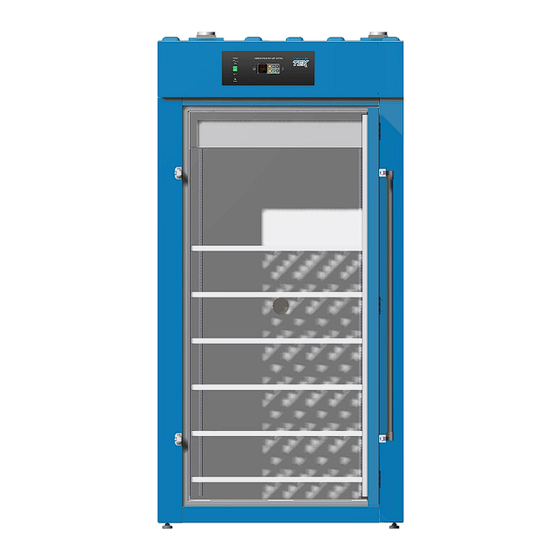
FORCED AIR OVENS TFO-28 TFO-10 Installation and Operation Manual... - Page 2 These ovens require permanent connect wiring (also known as hardwiring) to a power supply. Depicted on front cover: TFO-28 (left) and TFO-10 (right) Warning: This product contains chemicals, including triglycidyl isocyanurate, known to the State of California to cause cancer as well as birth defects or other reproductive harm. For more information, go to www.P65Warnings.ca.gov.
- Page 3 CTF1022-H CTF2822-H The Part ID denotes the specific build type of the model. This oven is manufactured for Cascade TEK by Sheldon Manufacturing, INC, an ISO-certified manufacturer. Safety Certifications These units are CUE listed by TÜV SÜD as forced air ovens for professional, industrial, or educational use where the preparation or testing of materials is done at an ambient air pressure range of 22.14 –...
-
Page 4: Table Of Contents
TABLE OF CONTENTS INTRODUCTION ..............................5 Read this Manual ..................................5 Safety Considerations and Requirements ........................5 Contacting Assistance ................................6 Manufacturing Warranty ..............................6 Engineering Improvements..............................6 RECEIVING YOUR OVEN ........................... 7 Inspect the Shipment ................................7 Orientation....................................8 Record The Data Plate Information .......................... -
Page 5: Introduction
INTRODUCTION Thank you for purchasing a Cascade TEK oven. We know you have many choices in today’s competitive marketplace when it comes to constant temperature equipment. We appreciate you choosing ours. We stand behind our products and will be here if you need us. -
Page 6: Contacting Assistance
Therefore, some changes, modifications, and improvements may not be covered in this manual. If your unit’s operating characteristics or appearance differs from those described in this manual, please contact your Cascade TEK dealer or customer service representative for assistance. -
Page 7: Receiving Your Oven
6. Verify that the correct number of accessory items has been included. Carefully check all packaging for accessories before discarding. Included accessory items Model Shelves Shelf Clips Leveling Feet TFO-10 12 Clips TFO-28 24 Clips Shelves TFO-10 TFO-28-2 P a g e... -
Page 8: Orientation
Control Panel Exhaust Vent Intake Vent Temperature Sensor Probes Permanent Connect Wire Braid 6 gauge, 6 inches (150 mm) Figure 1: TFO-28 Door Gasket Access Port (Back of Oven) Chamber Ceiling Liner Shelf Standard Mounting Rail P a g e... - Page 9 RECEIVING YOUR OVEN Figure 2: TFO-10 Fuse Holders for Accessory Power Supply Accessory Outlet Outlet 6-20R Wiring Braid (2 amps each) Access Port (Back of Oven) Power Panel (Back) Permanent Connect Wire Braid 6 gauge, 6 inches (150 mm) Intake Vent Control Panel Chamber Ceiling Exhaust Vent Liner...
-
Page 10: Record The Data Plate Information
RECEIVING YOUR OVEN ECORD LATE NFORMATION The data plate contains the unit model number, serial number, part number, and part ID. Customer Support will need this information during any support call. Record it below for future reference. The data plate is located on the back of the oven under the power inlet. •... -
Page 11: Installation
INSTALLATION ARDWIRE EQUIREMENT The oven requires permanent connect wiring (commonly known as hardwiring). Wiring to the power source must be performed by a qualified electrical technician. All other Installation steps may be performed by operators. NSTALLATION ROCEDURE HECKLIST For installing the unit in a workspace location. Pre-Installation ... -
Page 12: Required Ambient Conditions
Do not place objects on top of the oven. Exception: A power exhaust blower offered by • Cascade TEK may be mounted on the exhaust vent. Allow at least 6 inches (152 mm) from the fan vent on the back of the oven to the nearest •... -
Page 13: Power Source Requirements
Switch or circuit-breaker: A switch or circuit-breaker must be used in the building installation to protect against overcurrent conditions. The required circuit-breakers are TFO-10 30 amps, TFO-28 60 amps. • Power feed disconnect: The oven must be positioned so that all operators have access to the power feed disconnect in case of emergencies. -
Page 14: Power Feed Wiring
TFO-10 – two 6-gauge hot wires and a 6-gauge earth ground. • TFO-28 – two 6-gauge hot wires and a 6-gauge earth ground. • The wires for power source connection should be in accordance with the following for all units: Green/Yellow –... -
Page 15: Leveling
INSTALLATION EVELING Install the 4 leveling feet with the 4 corner holes on the bottom of the oven. The oven must be level and stable for safe operation. Note: To prevent damage when moving the unit, turn all 4 leveling feet so that the leg of each foot sits inside the oven. -
Page 16: Install The Shelving
INSTALLATION NSTALL THE HELVING The horizontal airflow within the chamber moves from the small duct holes on the right-hand side of the chamber to the large holes on the left side. Place the shelves as not to obstruct the duct holes on either side. -
Page 17: Graphic Symbols
GRAPHIC SYMBOLS The oven is provided with multiple graphic symbols on its external and internal surfaces. The symbols identify hazards and the functions of the adjustable components as well as important notes found in the operator manual. Symbol Definition Consult the operator manual Consulter le manuel d'utilisation Indicates adjustable temperature Indique température réglable... - Page 18 GRAPHIC SYMBOLS 18 | P a g e...
-
Page 19: Control Panel Overview
CONTROL PANEL OVERVIEW Figure 5: Control Panel and Controller Power Switch The switch illuminates when in the ON ( I ) position. Temperature Controller - Display on Homepage Top Line (Red): Present chamber air temperature Middle Line (Green): The constant temperature set point Bottom Line: Flashing “2”... - Page 20 CONTROL PANEL OVERVIEW 20 | P a g e...
-
Page 21: Operation
OPERATION Safe operation of the oven is dependent on the actions and behavior of the oven operators. Operating personnel must read and understand the Operating Precautions in this section prior to operating the oven. The operators must follow these instructions to prevent injuries and to safeguard their health, the environment, and the materials being treated in the oven, as well as to prevent damage to the oven. -
Page 22: Theory Of Operations
OPERATION HEORY OF PERATIONS Heating The oven temperature controller stores an operator-selected constant temperature set point. When powered, the oven heats the chamber atmosphere to the set point. The controller board is wired to a solid-state temperature probe located in the chamber on the rear wall. When the controller detects that the chamber temperature has dropped below the temperature setpoint, it pulses power to the heating elements. - Page 23 OPERATION Vents – Intake and Exhaust The oven is provided with an intake vent and exhaust vent that may be opened or closed using dampener slides located on the vents. The dampeners are intended to be opened after the heat treatment or bake out phases of an application are complete.
-
Page 24: Put The Oven Into Operation
OPERATION UT THE VEN INTO PERATION Verify all of the required procedures in the Installation section have been carried out. Then perform the following steps and procedures to prepare the oven for use in a new location. Power the Oven Place the oven Power Switch in the ON ( I ) position. -
Page 25: Set The High Temperature Limit
OPERATION ET THE EMPERATURE IMIT Note: Test the high limit system once per year for functionality. The high temperature limit is set by the operator at least 10°C above the highest temperature the oven will run at during your recipe profile or constant-temperature application. Advance to the Limit High SetPoint, starting on the Homepage Push the Advance button repeatedly until “Lh.S1”... -
Page 26: Setting The Constant Temperature Setpoint
OPERATION ETTING THE ONSTANT EMPERATURE ETPOINT Adjust the Constant Temperature Set Point on the Homepage Stay 10°C below the high limit • set point. Note: Holding down an arrow button will cause the temperature to advance in increments of ten (10). Adjust Release the Arrow buttons after adjusting the Setpoint There may be a brief pause as the oven controller... -
Page 27: High Temperature Limit Activated
OPERATION EMPERATURE IMIT CTIVATED The High Limit system blocks heating in the oven chamber if chamber temperature meets or exceeds the present High Limit setting. Heating remains disabled until the High Limit cutoff is manually cleared by the oven operator. Alternating Alert Screens Indicators The oven controller display screen flashes two alternating alert screens when a High... -
Page 28: Positive Exhaust Venting
OWER XHAUST LOWER Warning: Exposure to Cascade TEK offers an accessory forced-air power exhaust sustained oven chamber intended to mount directly on the exhaust vent and is temperatures above 80°C will powered by the oven. The exhaust blower is activated either damage the exhaust blower. -
Page 29: Data Port
OPERATION The 25-pin RS485 data port, located on the back of the oven, connects to the oven temperature controller. It is primarily intended for updating the controller software but can be used for data logging and graphical profile programming. Accessing the controller with a computer requires a 25- pin RS485-to-USB converter cable and driver software. -
Page 30: Auto Tuning
OPERATION UNING The auto tuning function runs the oven for a period of hours to optimize the controller PID parameters when running the oven with a large volume or mass of product in the oven chamber. PID optimization is intended to be used if the oven temperature is lagging, overshooting, or failing to achieve the setpoint under the above conditions. -
Page 31: Gn 2 Purge Option
OPERATION Note: The GN purge is not intended to enhance air exchange rates or ventilation. URGE PTION TFO ovens may be ordered with a gas nitrogen purge option. This is a special quote build and must be requested at the time of purchase, prior to construction of the oven. - Page 32 OPERATION Set Up Close the oven vents. Failure to close the vents compromises the integrity of the purge. a. Close both the intake and exhaust vents on the top of oven. b. Close the access port on the back of the oven. All 3 vents fully closed.
- Page 33 OPERATION Initiating the Purge There are two methods for starting the pruge. Manually initiating by turning the Event 1 parameter to on, or by setting the Event 1 parameter to on when programming a heating profile so the port opens automatically when the profile is running..
- Page 34 OPERATION 34 | P a g e...
-
Page 35: Operator Maintenance
OPERATOR MAINTENANCE Warning: Disconnect the unit from its power supply prior to maintenance or cleaning of this unit. Avertissement: Avant d'effectuer toute maintenance ou entretien de cet appareil, débrancher le cordon secteur de la source d'alimentation. LEANING If a hazardous material or substance has spilled in the unit, immediately initiate your site Hazardous Material Spill Containment protocol. -
Page 36: Door Gaskets And Chamber Integrity
Use proper PPE for handling exposed fiberglass when making the cuts. LECTRICAL OMPONENTS Electrical components do not require maintenance. If the oven fails to operate as specified, please contact your Cascade TEK distributor or Customer Support for assistance. 36 | P a g e... -
Page 37: Diagnostic Questionnaire - Heating Issues
OPERATOR MAINTENANCE — H IAGNOSTIC UESTIONNAIRE EATING SSUES If the unit is experiencing heating issues, use this questionnaire to gather information on the unit prior to contacting Customer Support. Gathering and sharing this information aids Customer Support in making timely and accurate remote diagnosis. Additionally, data logger files, as well as pictures and videos of the unit in its failure mode, are valuable diagnostic resources that can be shared with Customer Support. - Page 38 OPERATOR MAINTENANCE Note: Does the car actually have gas in the tank? Have you physically verified the computer is plugged in? Yes, we are going to ask some very basic questions. Please bear with us. Methodical verifications and the elimination of potential causes of failure are often the quickest means of getting a unit back into operation.
- Page 39 OPERATOR MAINTENANCE Optional: Obtain a temperature reference device. A calibrated digital thermometer with a thermocouple feedthrough. The device must be accurate to at least 0.1°C. Before Starting The unit must be connected to a power source that meets the requirements in the Installation chapter (page 13) and turned on.
- Page 40 OPERATOR MAINTENANCE Diagnostic Data Procedure – SDRAP Questions Record the answers in the log on page 41. etpoint? What is the current temperature setpoint? Chamber Temperature in Red Set Point in Green isplay? What chamber temperature is presently showing on the temperature display? eference? Optional: What temperature is the reference device presently showing for the chamber temperature?
- Page 41 OPERATOR MAINTENANCE SDRAP Data Log Record the SDRAP question answers in this log. These questions document the unit’s behavior. SDRAP Record SDRAP Answers and Any Notes Here et Point, present setting: isplay, present Temperature reading: eference device, present reading: mbient, present temperature: Heating Indicator: ilot Lights, illuminating...
- Page 42 OPERATOR MAINTENANCE 42 | P a g e...
-
Page 43: Unit Specifications
EIGHT Model Shipping Unit Weight TFO-10 450 lb / 204 kg 357.0 lb / 162.8 kg TFO-28 694.0 lb / 315 kg 563.0 lb / 255.4 kg IMENSIONS By Inches Model Exterior W × D × H Interior W × D × H TFO-10 44.0 x 28.3 x 55.1... -
Page 44: Capacity
UNIT SPECIFICATIONS APACITY Model Cubic Feet Liters TFO-10 10.0 TFO-28 28.0 Shelf Capacity by Weight Model Per Shelf Total TFO-10 75 lb / 34 kg 225 lb / 102 kg TFO-28 75 lb / 34 kg 450 lb / 204 kg... -
Page 45: Temperature Performance
UNIT SPECIFICATIONS EMPERATURE ERFORMANCE Range Model Range TFO-10 Ambient +15°C to 306°C TFO-28 Ambient +15°C to 306°C Uniformity Model @80°C @150°C @306°C TFO-10 1.0°C 1.5°C 5.0°C TFO-28 1.0°C 2.5°C 5.0°C Stability Model @80°C @150°C @306°C TFO-10 ± 0.2°C ± 0.3°C ±... -
Page 46: Power
Recovery Times from a 30 Second Door Opening Model @ 80°C @ 150°C @ 306°C TFO-10 3 Minutes 3 Minutes 6 Minutes TFO-28 3 Minutes 3 Minutes 5 Minutes Recovery Times from a 60 Second Door Opening Model @ 80°C @ 150°C @ 306°C... -
Page 47: Replacement Part List
1250512 9990741 Parts may be ordered from Cascade TEK by calling 1-888-835-9250. Please have the model, part, and serial numbers and Part ID of the unit ready, as Customer Support will need this information to match your oven with its correct part. - Page 48 Corporate Headquarters Cascade TEK Solutions, LLC 2010 Century Center Blvd, Suite 21 Irving, Texas 75062 support@cascadetek.com cascadetek.com 1-888-835-9250 1-971-371-4096...
Need help?
Do you have a question about the TFO-28 and is the answer not in the manual?
Questions and answers