
Related Manuals for Cascade TEK TVO-5-VC


Summary of Contents for Cascade TEK TVO-5-VC
-
Page 1: Installation And Operation Manual
Vacuum Ovens TVO-2-VC TVO-2-2-VC TVO-5-VC TVO-5-2-VC Installation and Operation Manual... - Page 2 The TVO-2-VC and TVO-5-VC ovens require a 110 – 120-volt power outlet. Standard NEMA 5-15R wall socket The TVO-2-2-VC and TVO-5-2-VC ovens require a 220 – 240 volt power outlet. Standard Standard NEMA 6-15R CEE7/7 wall socket wall socket Warning: This product contains chemicals, including triglycidyl isocyanurate, known to the State of California to cause cancer as well as birth defects or other reproductive harm.
- Page 3 CTVV522 CTVV522-EA The Part ID denotes the specific build version of the model. This oven is manufactured for Cascade TEK by Sheldon Manufacturing, INC, an ISO-certified manufacturer. Safety Certifications These units are CUE listed by TÜV SÜD as vacuum ovens for professional, industrial or educational use where the preparation or testing of materials is done at an ambient air pressure range of 22.14 –...
-
Page 4: Table Of Contents
TABLE OF CONTENTS INTRODUCTION ................................. 7 Read this Manual ..................................7 Safety Considerations and Requirements ........................7 Contacting Assistance ................................8 Manufacturing Warranty ..............................8 Engineering Improvements..............................8 Vacuum Supply Requirements ............................9 Compressed Air Supply Required ........................... 10 Oven Chamber Gaskets ..............................11 RECEIVING YOUR OVEN ............................ - Page 5 Capacity ....................................67 Shelf Capacity by Weight ..............................67 Vacuum ....................................68 Temperature ..................................68 Power ...................................... 68 PARTS LIST ................................69 Replacement Gaskets ................................ 70 P a g e...
- Page 6 TABLE OF CONTENTS P a g e...
-
Page 7: Introduction
INTRODUCTION Thank you for purchasing a Cascade TEK oven. We know you have many choices in today’s competitive marketplace when it comes to constant temperature equipment. We appreciate you choosing ours. We stand behind our products and will be here if you need us. -
Page 8: Contacting Assistance
Therefore, some changes, modifications, and improvements may not be covered in this manual. If your unit’s operating characteristics or appearance differs from those described in this manual, please contact your Cascade TEK dealer or customer service representative for assistance. -
Page 9: Vacuum Supply Requirements
INTRODUCTION ACUUM UPPLY EQUIREMENTS Pump or Building System Required The oven does not come with a vacuum pump. A pump must be separately purchased for the oven. Vacuum Pump Building Vacuum Supply Required Flow Rate For the chamber to seal, the vacuum pump or system must be able to evacuate at least 1 cubic foot per minute (cfm) for each cubic foot of oven chamber volume (CuFt). -
Page 10: Compressed Air Supply Required
INTRODUCTION OMPRESSED UPPLY EQUIRED The oven chamber cannot be pumped down or auto backfilled without a compressed air supply. Compressed air provides the mechanical pressure required to operate the automated vacuum and backfill valves on the back of the oven. Use ¼... -
Page 11: Oven Chamber Gaskets
INTRODUCTION HAMBER ASKETS Wear and Replacement Chamber liner gaskets are non-warranty, high-wear consumable items subject to compression forces, heat, and outgassed byproducts. Heavy usage rates may necessitate frequent replacements. The manufacturer strongly recommends keeping a spare gasket on hand during operation. Included Chamber Gasket Each oven comes with a replaceable silicone gasket installed on the chamber liner which seals the oven chamber when the door is closed and the chamber is under vacuum. - Page 12 INTRODUCTION 12 | P a g e...
-
Page 13: Receiving Your Oven
Tall Shelves Short Bottom Shelf Leveling Feet TVO-5-VCs Shelves Shelf Clips Leveling Feet Power Cords NEMA 5-15P NEMA 6-15P CEE 7/7 Model 125 Volt 240 Volt (US) 250 Volt (Euro) TVO-2-VC TVO-5-VC TVO-2-2-VC TVO-5-2-VC 13 | P a g e... -
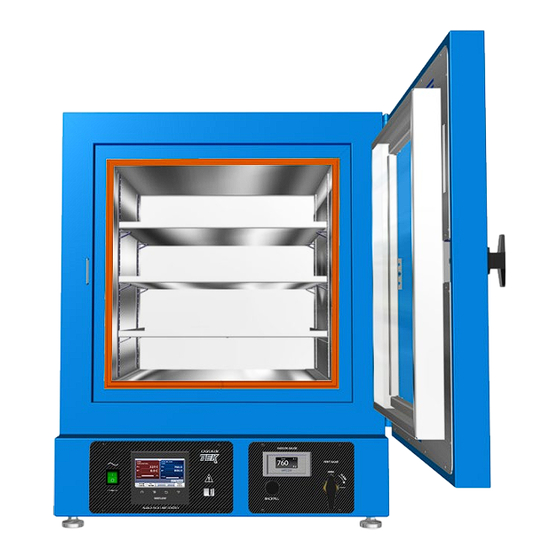
Page 14: Orientation Images
RECEIVING RIENTATION MAGES TVO-5-VC and TVO-5-2-VC Back of Units: See next page. Oven Chamber Door Chamber Gasket Seal Shelf Standard Rail Shelf Temperature Sensor Probe Leveling Foot (Below Shelf) Main Control Panel and Display Vacuum Display Panel Controller USB 14 |... - Page 15 RECEIVING Back of TVO-5-VC and TVO-5-2-VC Manometer KF-25 Auxiliary Access Port Vacuum Gauge Compressed Air In Port. ¼ inch (6.35 mm) Push Fitting. Chamber Manual Vent Inlet Port (manual backfill) ¼ inch (6.35 mm) KF-16 Automated Backfill Port KF-25 Automated...
- Page 16 RECEIVING TVO-2-VC and TVO-2-2-VC Back of Units: See next page. Tall Shelf Oven Chamber Door Tall Shelf Short Shelf (Bottom) Chamber Gasket Seal Main Control Panel and Display Temperature Probe Clip Vacuum Display Panel Controller USB 16 | P a g e...
- Page 17 RECEIVING Back of TVO-2-VC and TVO-2-2-VC KF-25 Auxiliary Access Port Manometer Vacuum Gauge Chamber Manual Vent Inlet Port (manual backfill) ¼ inch (6.35 mm) KF-16 Automated Backfill Port KF-25 Automated Vacuum Port Power Panel 15-Pin Voltage Output Port Ethernet Port Compressed Air In Port, ¼...
-
Page 18: Dimension Visuals
RECEIVING IMENSION ISUALS TVO-5-VCs See page 22 for the required ventilation clearances. Depth: 38.7 inches (983 mm) Height: 33.2 inches (844 mm) Exterior Width: 26.6 inches (676 mm) Chamber Height: 18.1 inches (459 mm) Chamber Depth: 24.1 inches (612 mm) Interior Chamber Width: 18.1 inches (459 mm) Shelves... - Page 19 RECEIVING TVO-2-VCs See page 22 for the required ventilation clearances. Depth: 34.9 inches (887 mm) Height: 27.1 inches (689 mm) Exterior Width: 20.2 inches (513 mm) Chamber Height: 12.0 inches (304 mm) Chamber Depth: 20.0 inches (508 mm) Interior Chamber Width: 12.0 inches (304 mm) Tall Shelves Shelf Depth: 19.0 inches (483 mm)
-
Page 20: Record The Data Plate Information
RECEIVING ECORD THE LATE NFORMATION The data plate contains the unit model number, serial number, part number, and part ID. Customer Support will need this information during any support call. Record it below for future reference. The data plate is located on the back of the oven above the power inlet. •... -
Page 21: Installation
INSTALLATION NSTALLATION ROCEDURES HECKLIST For installing the oven in a new workspace location. Pre-Installation Verify a vacuum supply source suitable for your application is available and can be connected to the oven, page 9. See page 29 for the oven gas and vacuum port locations. •... -
Page 22: Required Ambient Conditions
INSTALLATION EQUIRED MBIENT ONDITIONS This oven is built for use indoors at room temperatures between 15°C and 40°C (59°F and 104°F), at no greater than 80% Relative Humidity (at 25°C / 77°F). The ambient temperature should not change by 2°C (3.6°F) or more during operation. Operating outside these conditions may adversely affect the oven temperature performance. -
Page 23: Power Source Requirements 110 - 120 Volts
The fuse must be installed and intact for the unit to operate. • Always find and fix the cause of a blown fuse prior to putting the unit back into operation. • Fuse type, TVO-2-VC and TVO-5-VC: • T16A, 250V 5x20mm 23 |... -
Page 24: Power Source Requirements 220 - 240 Volts
INSTALLATION 220 – 240 V OWER OURCE EQUIREMENTS OLTS TVO-2-2-VC TVO-5-2-VC When selecting a location for the unit, verify each of the following requirements is satisfied. Power Source: The wall power outlet must meet the power requirements listed on the unit data plate. -
Page 25: Lifting And Handling
INSTALLATION IFTING AND ANDLING The oven is heavy. Use appropriate lifting devices that are sufficiently rated for these loads. Follow these guidelines when lifting the oven: Lift the oven only from its bottom surface. • Doors, handles, and knobs are not adequate for lifting or stabilization. •... -
Page 26: Install The Oven
INSTALLATION NSTALL THE Install the unit in a workspace location that meets the criteria discussed in the previous entries of the Installation section. Do not connect the oven to its power source at this time. • NSTALLATION LEANING The manufacturer recommends cleaning the shelving and oven chamber prior to installation of the shelving in the chamber. -
Page 27: Shelving Installation
INSTALLATION HELVING NSTALLATION Heating in a vacuum environment takes place primarily through conduction. Heat flows from oven elements inside the chamber walls and floor to the shelves. Install the shelves as described below to ensure proper heat conduction and temperature measurement. Never place samples or product on the oven chamber floor. - Page 28 INSTALLATION Shelving Installation Continued TVO-5-VCs Shelving To ensure accurate temperature measurement, one shelf bottom must be in close proximity to the oven temperature probe. This probe extends out from the chamber back wall. Do not place the shelf in direct contact with the probe. Shelf Probe Install 4 Shelf Clips...
-
Page 29: Connect To The Vacuum And Gas Supplies
INSTALLATION ONNECT TO THE ACUUM AND UPPLIES KF-25 Auxiliary Port 3. Optional: Connect a gas backfill supply to the KF-16 Automated backfill port. 1. Connect your compressed air supply to the ¼ inch (6.35 mm) compression fitting, 70 psi required. Never exceed 80 psi. - Page 30 INSTALLATION 30 | P a g e...
-
Page 31: Graphic Symbols
GRAPHIC SYMBOLS The oven is provided with multiple graphic symbols on its interior and exterior surfaces. The symbols identify hazards and the functions of the adjustable components, as well as important notes in the operator manual. Symbol Definition Consult the operator manual Consulter le manuel d'utilisation AC Power Repère le courant alternatif... - Page 32 SYMBOLS 32 | P a g e...
-
Page 33: Control Overview
CONTROL OVERVIEW Main Control Panel Vacuum Panel Main Control Panel Power Switch The switch illuminates when in the ON ( I ) position. Oven Temperature and Vacuum Controller Home Returns the display to the homepage. Menu Accesses the password for unlocking the heating profile programming menu. - Page 34 CONTROLS Oven Temperature Tab PV: The present oven chamber temperature. When the chamber is pumped down, this Process Value measures the temperature of the shelving in the vacuum environment. When atmosphere is present in the chamber, the PV is a measurement of that gas temperature. SP: Setpoint.
- Page 35 CONTROLS Vacuum Control Tapping this button turns on the Vacuum Control function. Vacuum Control actively adjusts the oven chamber vacuum valve to achieve and then maintain a pressure level between room atmosphere pressure and 1 torr. This level can be set by the operator using the homepage vacuum tab setpoint or programmed as part of an automated heating profile.
- Page 36 CONTROLS Oven Limit Page The Oven Limit system routes power away from the heating elements during over temperature events, preventing further overheating. See page 39. Vacuum Panel Vacuum Gauge ~810 torr – Room atmosphere pressure for pure N atmosphere at or near sea level This display connects to a gauge that measures the pressure of pure nitrogen (N ) and shows the chamber pressure level in torr and millitorr (mTorr).
-
Page 37: Operation
OPERATION Safe operation of the oven is dependent on the actions and behavior of the oven operators. Operating personnel must read and understand the Operating Precautions in this section prior to operating the oven. The operators must follow these instructions to prevent injuries and to safeguard their health, environment, and the materials being treated in the oven, as well as to prevent damage to the oven. -
Page 38: Theory Of Operation
OPERATION HEORY OF PERATION Vacuum Vacuum is supplied by an external vacuum pump connected to the pneumatic vacuum valve port on the back of the oven. The valve is controlled by the oven Full Vacuum and Vacuum Control functions. Full vacuum opens the valve all the way and holds it there, pumping down the chamber using the best flow rate of the supply pump. - Page 39 OPERATION Heating in a Vacuum In conventional ovens, powered elements transfer heat into the chamber air. The hot air then circulates by natural convection or blower fan action, surrounds the product on the shelves, gradually bringing it to temperature. In a vacuum oven, heat transfer occurs in part through direct infrared radiation.
-
Page 40: Put The Oven Into Operation
OPERATION UT THE VEN INTO PERATION Perform the procedures below after the unit has been installed in a new workplace location. These verify the integrity of the vacuum system and prepare the oven for normal use. Attach the Power Cord Attach the power cord that came with the unit to the power inlet receptacle on the back of the oven. - Page 41 OPERATION Continued from the previous page Verify the vacuum system integrity Use the Pump Down the Oven Chamber procedure on page 43 to pump down and hold the oven chamber under vacuum for 10 minutes to verify the integrity of the vacuum supply system.
-
Page 42: Set The Oven Limit Temperature
OPERATION ET THE IMIT EMPERATURE Note: Test the oven limit system once per year for functionality. Set the oven temperature limit at least 10°C above the highest temperature the oven will run at during your recipe program or constant-temperature application. See page 39 for the system explanation. Open the Oven Limit Page Tap the homepage arrow button. -
Page 43: Pump Down The Oven Chamber
OPERATION OWN THE HAMBER Note: Perform a Full Vacuum evacuation of the chamber for at least 10 minutes when first putting the oven into operation in a new location to verify the vacuum supply system integrity. Use Method 2. Always verify the manual backfill vent valve is in the closed position. Reminder: The measured chamber temperature will drop Close when pumping atmosphere out of the oven. - Page 44 OPERATION Method 2 – Manually Turn On Full Vacuum Opens the vacuum valve to its maximum position. Turn on the vacuum pump or supply source connected to the oven Vacuum Valve. 2. Tap the Full Vacuum button on the homepage, fully opening the Vacuum Valve. The chamber will evacuate to the lowest pressure allowed by the pump and samples.
-
Page 45: Backfilling The Chamber
OPERATION ACKFILLING THE HAMBER Atmosphere is restored to the chamber in two stages. Stage 1: Automatic Partial Backfill Two triggers cause the oven to turn off the vacuum pump and partly backfill to a range of 600 – 700 torr as measured on the Vacuum Gauge. Manual Trigger When both vacuum functions are manually turned off. -
Page 46: Manually Backfilling
OPERATION Stage 2: Manual Backfill to Room Pressure Press and hold the Backfill button on the Vacuum Panel. The chamber will begin to backfill. Release the button when the chamber has reached room pressure. ANUALLY ACKFILLING In the event of a power outage or emergency, the manual Vent Valve control on the Vacuum Panel can be used to restore atmosphere to the chamber. -
Page 47: Setting A Constant Temperature Setpoint
OPERATION ETTING A ONSTANT EMPERATURE ETPOINT Note: Heating to your baking application temperature with atmosphere in the chamber will result in a drop in temperature when the chamber is evacuated. It may also oxidize chamber surfaces. Enter Oven heating to the new setpoint To end heating, enter a setpoint of 0. -
Page 48: Oven Limit Active
OPERATION IMIT CTIVE Limit activations serve as a persistent, protective interruption of heating in the oven chamber. Always identify and correct the cause of an oven limit activation before restoring heating. Homepage in Alarm mode The chamber temperature exceeds both the Oven Limit setting and the Temperature Setpoint Note: The oven chamber is not heating in the example above. - Page 49 OPERATION Reminder: Always identify and correct the cause of an oven limit activation before restoring heating. Clearing an Active Limit Cutoff The oven shelving temperature must return to below the Oven Limit setting before Alarm Message: This alert window appears the first time a button is a Limit cutoff can be cleared (canceled).
-
Page 50: Data Ports
OPERATION ORTS Front of Unit USB Port Located on the front control panel, this gives access to the main oven controller and can be used for the following: Uploading heating profiles to the controller. • Programming heating profiles on a desktop or laptop environment. •... -
Page 51: Password
OPERATION ASSWORD The Oven Temperature and Vacuum controller comes from the factory locked with the following default password: ctek The controller must be unlocked by logging in with the password in order to do the following: Program new heating profiles •... - Page 52 OPERATION 52 | P a g e...
-
Page 53: Operator Maintenance
OPERATOR MAINTENANCE Warning: Disconnect the unit from its power supply prior to maintenance or cleaning. Avertissement: Avant d'effectuer toute maintenance ou entretien de cet appareil, débrancher le cordon secteur de la source d'alimentation. LEANING If a hazardous material or substance has spilled in the unit, immediately initiate your site Hazardous Material Spill Containment protocol. -
Page 54: Maintaining Atmospheric Integrity
MAINTENANCE Oven Exterior Cleaning Guidelines Disconnect the unit from its power supply. 2. The manufacturer recommends cleaning the unit with a mild soap and water solution. Do not use abrasive cleaners, these will damage metal surfaces. • Cleaning agents must be compatible with steel and powder coat paint surfaces. •... -
Page 55: Heating Issues - Diagnostic Questionnaire
MAINTENANCE — D EATING SSUES IAGNOSTIC UESTIONNAIRE If the unit is experiencing heating issues, use this questionnaire to gather information on the unit prior to contacting Customer Support. Gathering and sharing this information aids Customer Support in making timely and accurate remote diagnoses. Additionally, datalogger files, as well as pictures and videos of the unit in its failure mode, are valuable diagnostic resources that can be shared with Customer Support. - Page 56 MAINTENANCE Note: Does the car actually have gas in the tank? Have you physically verified the computer is plugged in? Yes, we are going to ask some very basic questions. Please bear with us. Methodical verifications and the elimination of potential failure causes are often the quickest means of getting a unit back into operation.
- Page 57 MAINTENANCE Optional: Obtain a temperature reference device. A calibrated digital thermometer with a vacuum- rated thermocouple feedthrough. The device must be accurate to at least 0.1°C. Preparing for the Heating Diagnostic Observations The unit must be connected to a power source that meets the requirements in the Installation chapter (page 23) and turned on.
- Page 58 MAINTENANCE Heating Diagnostic Questions Record the answers in the log on page 59. etpoint? Process Value What is the current temperature setpoint? Constant Temperature Setpoint Power Bar isplay? 1) What Process Value is showing on the controller Oven Temp tab? 2) Is the Oven Temp power bar indicating that the oven is drawing power to heat the chamber, Y/N? eference?
- Page 59 MAINTENANCE Heating Diagnostic Data Log Record the answers to the Heating Diagnostic questions in this table. These questions document the unit behavior. Diagnostic Questions Record Answers and Any Notes Here etpoint, present reading: Temperature Process Value reading: isplay, Oven Temp tab: Power Bar, present heating power percentage: eference Device, present reading...
-
Page 60: Vacuum Leak Issues - Diagnostic Questionnaire
MAINTENANCE Vacuum Leak Issues – D IAGNOSTIC UESTIONNAIRE If the unit is experiencing vacuum leak issues, use this questionnaire to gather information on the unit prior to contacting Customer Support. Gathering and sharing this information aids Customer Support in making timely and accurate remote diagnoses. - Page 61 MAINTENANCE Does the car actually have gas in the tank? Have you physically verified the computer is Note: plugged in? Yes, we are going to ask some very basic questions. Please bear with us. Methodical verifications and the elimination of potential causes of failure are often the quickest means of getting a unit back into operation.
- Page 62 MAINTENANCE Vacuum Diagnostic Setup Check the primary chamber gasket for damage. This is the gasket mounted on the chamber liner that seals the oven chamber when the door is closed. Look for: Cuts or nicks on the gasket caused by removing shelves or samples •...
- Page 63 MAINTENANCE Vacuum Diagnostic Questions Record the answers in the log on page 66. ump On and Running? Yes or no? ull Vacuum Turned On? Is Full Vacuum turned on from the oven controller homepage? Use Full Vacuum for this diagnostic procedure to ensure the oven is under the full achievable vacuum draw.
- Page 64 MAINTENANCE ir Pressure? Record the Air Pressure Regulator reading. 70 psi of air pressure is required to supply the mechanical force used to open and close the vacuum and backfill valves. Insufficient pressure will prevent the oven from fully evacuating. Air Pressure Regulator isplay Values? 1.
- Page 65 MAINTENANCE eak Rate? Calculate and record the leak rate of the evacuated and isolated oven chamber: 1. Verify the oven chamber and shelving are at room temperature (20 – 25°C). 2. Verify the oven chamber is clean and dry to prevent outgassing from contaminants or water. 3.
- Page 66 MAINTENANCE Vacuum Leak Diagnostic Data Log Record the diagnostic question answers in this log. These questions document the unit behavior. Diagnostic Questions Record Answers and Any Notes Here ump on and running, Y/N? ull Vacuum Turned On, Y/N? acuum Valve Open, Y/N? ir Pressure, Present Reading: Vacuum Tab reading: isplay Readings:...
-
Page 67: Unit Specifications
UNIT SPECIFICATIONS Please refer to the oven data plate for individual electrical specifications. Technical data specified applies to units with standard equipment at an ambient temperature of 25°C and at nominal voltage. The temperatures specified are determined in accordance with factory standard following DIN 12880 respecting the recommended wall clearances of 10% of the height, width, and depth of the inner chamber. -
Page 68: Vacuum
230°C. See page 70 for the temperature ranges of other gasket types. OWER Model AC Voltage Amperage Frequency TVO-2-VC 110 – 120 10.0 50/60 Hz TVO-5-VC 110 – 120 13.0 50/60 Hz TVO-2-2-VC 220 – 240 50/60 Hz TVO-5-2-VC 220 – 240 50/60 Hz 68 |... -
Page 69: Parts List
Shelf Clip, Individual (1), T10A 250V 5x20mm TVO-5-VCs (Requires 2) 3300516 1250510 Power Cord, TVO-2-VC Shelf, TVO-5-VCs and TVO-5-VC 125 volt, 15 Amp, 9ft 5in (2.86m) NEMA 5-15P 1800510 5680563 Power Cord, TVO-2-2- VC and TVO-5-2-VC 240 volt, 15 Amp, 8ft 2in (2.5m) NEMA 6-15P... -
Page 70: Replacement Gaskets
(457 x 457 mm) Ordering Parts and Consumables Parts may be ordered from Cascade TEK by calling 1-888-835-9250. Please have the model, part, and serial numbers and Part ID of the unit ready, as Customer Support will need this information to match your unit to its correct part. - Page 71 PARTS 71 | P a g e...
- Page 72 Corporate Headquarters Cascade TEK Solutions, LLC 2010 Century Center Blvd, Suite 21 Irving, Texas 75062 support@cascadetek.com cascadetek.com 1-888-835-9250 1-971-371-4096...
Need help?
Do you have a question about the TVO-5-VC and is the answer not in the manual?
Questions and answers