Table of Contents
Advertisement
Quick Links
Advertisement
Table of Contents

Related Manuals for Cascade TEK SVO-10-VC


Summary of Contents for Cascade TEK SVO-10-VC
- Page 1 Vacuum Control Oven SVO-10-VC Installation and Operation Manual...
- Page 2 Manufacturing Warranty For warranty information outside the USA please visit: www.cascadetek.com/resource/limited-international-warranty-policy-cascade-tek-solution-llc For warranty information inside the USA please visit: www.cascadetek.com/resource/limited-usa-warranty-policy-–-cascade-tek-solutions-llc P a g e...
- Page 3 Vacuum Control Oven 220 – 240 Voltage Part Number (Manual): 4861811 Revision: March 28, 2018 Cascade TEK is a brand of Sheldon Manufacturing, INC. Safety Certifications These units are CUE listed by TÜV SÜD as vacuum ovens for professional, industrial or educational use where the preparation or testing of materials is done at an ambient air pressure range of 22.14 –...
-
Page 4: Table Of Contents
TABLE OF CONTENTS INTRODUCTION ................................. 7 Read this Manual ..................................7 Safety Considerations and Requirements ........................7 Contacting Assistance ................................8 Engineering Improvements..............................8 Vacuum Pump Options ................................. 9 Compressed Air Supply Required ............................. 9 Gasket Chemical Vulnerabilities ............................10 RECEIVING YOUR OVEN ............................11 Inspect the Shipment ................................ - Page 5 REPLACEMENT PARTS LIST........................... 61 P a g e...
- Page 6 TABLE OF CONTENTS P a g e...
-
Page 7: Introduction
INTRODUCTION Thank you for purchasing a Cascade TEK oven. We know you have many choices in today’s competitive marketplace when it comes to constant temperature equipment. We appreciate you choosing ours. We stand behind our products and will be here if you need us. -
Page 8: Contacting Assistance
Therefore, some changes, modifications, and improvements may not be covered in this manual. If your unit’s operating characteristics or appearance differs from those described in this manual, please contact your Cascade TEK dealer or customer service representative for assistance. -
Page 9: Vacuum Pump Options
INTRODUCTION ACUUM PTIONS SVO-10-VC ovens can be ordered with one of several vacuum pump types installed inside the oven utility cabinet. These pumps vary in evacuation flow rates and suitability for different baking applications. Refer to the vacuum pump manufacturer manual included with the oven for specifications and compatibility with applications. -
Page 10: Gasket Chemical Vulnerabilities
INTRODUCTION ASKET HEMICAL ULNERABILITIES The oven comes with a Viton® gasket built into the oven door. The gasket must seal against the un- nicked contact surface on the oven body in order for the oven chamber to hold vacuum. The gasket is a low wear, long-duration component that is rated to 220°C and typically replaced only during scheduled services on the oven. -
Page 11: Receiving Your Oven
6. Verify the correct number of accessory items has been included. Carefully check all packaging for accessories before discarding. Included Accessory Items: SVO-10-VC Leveling Feet Shelf Shelf Clip... -
Page 12: Orientation Images
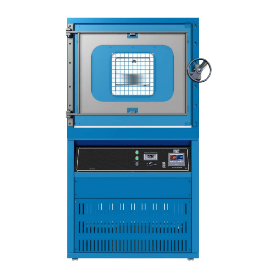
RECEIVING YOUR OVEN RIENTATION MAGES SVO-10-VC Temperature Probe Door Latch Shelf Standard Mounting Rail Shelf (Below Shelf) Control Panel Door Hasp Door Gasket Oven Chamber Door 12 | P a g e... - Page 13 RECEIVING YOUR OVEN Back of Oven – SVO-10-VC Auxiliary Chamber Port (KF-25) Compressed Air Port ¼ inch (6.35 mm) Push Fitting Backfill Port 3/8 inch (9.5 mm) Hardwire Power Feed Vacuum Exhaust Tubing Data Plate (standard pump units) 13 |...
-
Page 14: Record Data Plate Information
RECEIVING YOUR OVEN ECORD LATE NFORMATION Record the unit serial number and model number below for future reference. Tech Support needs this information to provide accurate help during support calls and emails. • The data plate is located on the back, left side of the oven, above the gas inlet port. Model Number Serial Number 14 |... -
Page 15: Installation
INSTALLATION ARDWIRE EQUIREMENT The oven requires permanent connect wiring (commonly known as hardwiring). Wiring to the power source must be performed by a qualified electrical technician. All other Installation steps may be performed by the operator. NSTALLATION ROCEDURE HECKLIST For installing the unit in a new workspace location. Pre-Installation ... -
Page 16: Required Ambient Conditions
INSTALLATION EQUIRED MBIENT ONDITIONS When selecting a location to install the unit, consider all environmental conditions that can adversely impact its temperature performance. These include: Proximity to other ovens, autoclaves, and any device that produces significant radiant heat • Heating and cooling vents or other sources of fast-moving air currents •... -
Page 17: Power Source Requirements
(located on the back of the unit, above the gas inlet port): Model AC Voltage Amperage Phase Frequency SVO-10-VC 220 – 240 50/60 Hz The power source must be protective earth grounded. The source must conform to all • national and local electrical codes. -
Page 18: Power Feed Wiring
INSTALLATION OWER IRING The oven comes provided with an integral 6-inch (150-mm) wire braid consisting of: Two 10-gauge hot wires – black • One 10-gauge earth ground – green-yellow • The oven must be earth grounded using the protective conductor terminal (green with yellow stripe wire). -
Page 19: Leveling
INSTALLATION EVELING Install the 4 leveling feet in the corner holes in the bottom of the oven. The oven must be level and stable for safe operation. To prevent damage when moving the unit, turn all 4 leveling feet so that the leg of each foot Note: sits inside the unit. -
Page 20: Shelving Installation
INSTALLATION HELVING NSTALLATION To ensure accurate temperature measurement, one shelf bottom must be in close proximity to the oven temperature probe. This probe extends out from the chamber back wall. Do not place the shelf in direct contact with the probe. Shelf Probe Install 6 Shelf Clips... -
Page 21: Connect Venting And Gas Supplies
INSTALLATION ONNECT ENTING AND UPPLIES Optional: Connect equipment to the KF-25 auxiliary port. Comes with a blank and clamp. 1. Compressed air supply connects to this ¼ inch (6.35 mm) push fitting. Requires 70 psi of delivered pressure at this port. Never exceed 80 psi. -
Page 22: Venting Pump Exhaust
INSTALLATION Note: Outgassed byproducts may be hazardous to or noxious for operating personnel. Vacuum pump exhaust should be vented to a location outside the workspace in a safe manner in accordance with all applicable laws, ordinances, and regulations. ENTING XHAUST The oven comes with a vacuum pump installed in the electronics cabinet at the base of the oven. -
Page 23: Graphic Symbols
GRAPHIC SYMBOLS The oven is provided with multiple graphic symbols on its interior and exterior surfaces. The symbols identify hazards and the functions of the adjustable components, as well as important notes in the user manual. Symbol Definition Consult the user manual Consulter le manuel d'utilisation AC Power Repère le courant alternatif... - Page 24 GRAPHIC SYMBOLS 24 | P a g e...
-
Page 25: Control Overview
CONTROL OVERVIEW Main Control Panel Oven Temperature and Vacuum Controller Present Value Present Value Setpoint Setpoint Home Returns the display to the homepage. Menu Accesses the password for unlocking the heating profile programming menu. Return Returns the display to the previous page or menu. - Page 26 CONTROL OVERVIEW Oven Temperature Tab Present temperature value (PV) of the oven chamber 48.1°C A constant temperature setpoint (SP) of 150.0°C entered on the setpoint button Oven heating with 50% power (PWR) PV: When the oven chamber is evacuated, the PV measures the temperature of the shelving.
- Page 27 CONTROL OVERVIEW Note: Both vacuum functions can be manually turned on from the homepage by tapping the button or turned on as a heating profile step parameter. The button indicator disk changes from gray to green when turned on. Vacuum Control The Vacuum Control function dynamically adjusts the chamber vacuum valve to achieve and then maintain a pressure level between 760 and 1 torr.
- Page 28 CONTROL OVERVIEW Controller Oven Limit Page The independent circuitry and temperature sensor of the Oven Limit System routes power away from the heating elements, preventing heating during over temperature events. See page 31. Vacuum Gauge – Chamber Pressure Display Shows the chamber pressure level in torr and millitorr (mTorr). To show the chamber pressure in units other than torr, see the vacuum gauge user manual, which comes included with the oven.
-
Page 29: Operation
OPERATION Safe operation of the oven is dependent on the actions and behavior of the oven operators. Operating personnel must read and understand the Operating Precautions in this section prior to operating the oven. The operators must follow these instructions to prevent injuries and to safeguard their health, environment, and the materials being treated in the oven, as well as to prevent damage to the oven. -
Page 30: Theory Of Operation
OPERATION HEORY OF PERATION Vacuum and Vacuum Automation These ovens are intended for use in closed-cycle, under-vacuum applications. The chamber must be sealed and evacuated at the start of a vacuum baking application. The oven is not built to operate with the chamber exposed to free atmosphere. - Page 31 OPERATION Heating in a Vacuum In conventional ovens, powered elements transfer heat into the chamber air. The heated air then circulates by natural convection or blower fan action and surrounds the product on the shelves, gradually bringing it to temperature. In a vacuum oven, heat transport takes place primarily by conduction.
-
Page 32: Put The Oven Into Operation
OPERATION UT THE VEN INTO PERATION Verify all required procedures in the Installation chapter have been carried out. Then perform the following steps and procedures to prepare the oven for use in a new location. Turn on the oven Verify the oven vacuum integrity Place the Chamber Under Full Vacuum for a minimum of 10 minutes to verify the integrity of the vacuum system. -
Page 33: Evacuating The Oven Chamber
OPERATION VACUATING THE HAMBER Note: Perform a Full Vacuum evacuation of the chamber for at least 10 minutes when first putting the oven into operation in a new location to verify the vacuum supply system integrity. The oven door must be closed and latched prior to activating either of the vacuum functions. An operator must always be present while the oven is drawing a vacuum. - Page 34 OPERATION Option 2 – Manually Turn On Full Vacuum Opens the vacuum valve to its maximum position. Turn on the oven vacuum pump. a. Tap Pump Start. 2. Turn on Full Vacuum on the homepage. • The chamber will evacuate to the lowest pressure allowed by the pump and samples. Vacuum Valve Chamber evacuated 100% open...
- Page 35 OPERATION Option 3 – Automate the Vacuum Functions Note: Pump Start cannot be turned on automatically. An operator must always be present to turn on the vacuum pump. The Vacuum Control or Full Vacuum functions may be set to automatically turn on as part of a heating profile.
-
Page 36: Backfilling The Chamber
OPERATION ACKFILLING THE HAMBER Atmosphere is restored to the chamber in two stages. Stage 1: Automatic Partial Backfill Two triggers cause the oven to turn off the vacuum pump and partly backfill to a range of 600 – 700 torr. Manual Trigger When both Vacuum functions are manually turned off. -
Page 37: Set The Oven Limit Temperature
OPERATION ET THE IMIT EMPERATURE Note: Test the oven limit system once per year for functionality. The oven limit is set by the operator. Bring up the Oven Limit Page Tap the homepage arrow button. Bring up the Setpoint Programming Page Tap the High Limit Setpoint Button. -
Page 38: Setting A Constant Temperature Setpoint
OPERATION ETTING A ONSTANT EMPERATURE ETPOINT Note: Heating to your baking application temperature with atmosphere in the chamber will result in a drop in temperature when the chamber is evacuated. It may also oxidize chamber surfaces. Enter Oven heating to the new setpoint To end heating, enter a setpoint of 0. -
Page 39: Password
OPERATION ASSWORD The Oven Temperature and Vacuum controller comes from the factory locked with the following default password: ctek The controller must be unlocked by logging in with the password in order to do the following: • Program new heating profiles •... -
Page 40: Oven Limit Active
OPERATION IMIT CTIVE Limit activations serve as a persistent, protective interruption of heating in the oven chamber. Always identify and correct the cause of an oven limit activation before restoring heating. Oven Limit Heating Cutoff Active The chamber temperature exceeds both the Oven Limit Setting and the Temperature Setpoint Note: The oven chamber is not heating in the example above. - Page 41 OPERATION Reminder: Always identify and correct the cause of an oven limit activation before restoring heating. Clearing an Active Limit Cutoff The oven shelving temperature must be below the Oven Limit setting before a Alarm Message: This alert window appears the first time a button is Limit Cutoff can be cleared (canceled).
-
Page 42: Data Ports
OPERATION ORTS Front of Unit USB Port The USB port located on the font control panel accesses the Temperature and Vacuum controller and can be used for the following: Downloading heating profiles from the controller • Updating firmware • Back of the Oven Ethernet Port The ethernet port located on the back of the oven accesses the Temperature and Vacuum controller. -
Page 43: Operator Maintenance
OPERATOR MAINTENANCE Warning: Disconnect the unit from its power supply prior to maintenance or service. Avertissement: Avant d'effectuer toute maintenance ou entretien de cet appareil, débrancher le cordon secteur de la source d'alimentation. LEANING If a hazardous material or substance has spilled in the unit, immediately initiate your site Hazardous Material Spill Containment protocol. -
Page 44: Maintaining Atmospheric Integrity
OPERATOR MAINTENANCE AINTAINING TMOSPHERIC NTEGRITY Periodically, inspect the door latch, trim, catch, and gasket for signs of deterioration. Failure to maintain the integrity of the door system shortens the lifespan of the unit. LECTRICAL OMPONENTS Electrical components do not require maintenance. If the oven fails to operate as specified, please contact your distributor or Technical Support for assistance. -
Page 45: Diagnostic Questionnaire - Heating Issues
OPERATOR MAINTENANCE – H IAGNOSTIC UESTIONNAIRE EATING SSUES If the unit is experiencing heating issues, use the following questionnaire to gather information on the unit prior to contacting Technical Support. Additionally, data logger files as well as pictures and videos of the unit in failure mode are valuable diagnostic resources you can share with Tech Support. - Page 46 OPERATOR MAINTENANCE Does the car actually have gas in the tank? Have you physically verified the computer is Note: plugged in? Yes, we are going ask some very basic questions. Please bear with us. Methodical verifications and the elimination of potential causes of failure are often the quickest means of getting a unit back into operation.
- Page 47 OPERATOR MAINTENANCE Optional: Obtain a temperature reference device. A calibrated digital thermometer with a vacuum- rated thermocouple feedthrough. The device must be accurate to at least 0.1°C. Before Starting The unit must be connected to a power source that meets the requirements in the Installation chapter (page 17) and turned on.
- Page 48 OPERATOR MAINTENANCE Diagnostic Data Procedure – SDHRAP Questions Record the answers in the log on page 50. Setpoint What is the current temperature setpoint of the unit? See the Setting a Constant Temperature Setpoint entry in the Operation chapter. Present Value Constant Temperature Setpoint isplay?
- Page 49 OPERATOR MAINTENANCE mbient? What is the room temperature? • For best results, measure the temperature in the same section of the room where the unit is located. Do not place your thermometer on the unit. • Review the required Ambient Conditions topic in the Installation chapter (page Error! Bookmark not defined.).
- Page 50 OPERATOR MAINTENANCE SDHRAP Data Log Record the answers to the SDHRAP questions in this table. These questions document the unit’s behavior. SDHRAP Record SDHRAP Answers and Any Notes Here etpoint, present reading: isplay, present temperature reading: igh Limit Activated Y/N?: eference Device, present reading (optional): mbient, present temperature:...
- Page 51 OPERATOR MAINTENANCE IAGNOSTIC UESTIONNAIRE ACUUM SSUES If the unit is experiencing problems achieving or holding a vacuum level, use this questionnaire to gather onsite information on the unit prior to contacting Technical Support. Additionally, datalogger files as well as pictures or videos of the unit in failure mode are valuable diagnostic resources to share with Tech Support. Gathering and sharing this information aids Tech Support in making timely and accurate remote diagnoses.
- Page 52 OPERATOR MAINTENANCE Does the car actually have gas in the tank? Have you physically verified the computer is Note: plugged in? Yes, we are going ask some very basic questions. Please bear with us. Methodical verifications and the elimination of potential causes of failure are often the quickest means of getting a unit back into operation.
- Page 53 OPERATOR MAINTENANCE Diagnostic Setup Check the primary chamber gasket for damage. This is the gasket mounted on the chamber liner and seals the oven chamber when the door is closed. Look for: Cuts or nicks on the gasket caused by removing shelves or samples from the chamber. •...
- Page 54 OPERATOR MAINTENANCE Diagnostic Data Procedure Record answers to the below questions in the Vacuum Diagnostic Log on page 57. ump On and Running? Yes or no? The pump must be connected to the oven, plugged in, and on. ump Start Turned On? Tapping the pump start function turns on the oven vacuum pump.
- Page 55 OPERATOR MAINTENANCE ir Pressure? Record the Air Pressure Regulator reading. 70 psi of air pressure is required to supply the mechanical force used to open and close the vacuum and backfill valves. Insufficient pressure will prevent the oven from fully evacuating. Air Pressure Regulator Setpoint Record the current setpoint if you are using the Vacuum Control function.
- Page 56 OPERATOR MAINTENANCE eak Rate? Calculate and record the leak rate of the sealed vacuum chamber: If oven is hot, allow oven to cool to ambient temperature. 2. Turn on the Pump Start button. 3. Turn on the Full Vacuum Function. 4.
- Page 57 OPERATOR MAINTENANCE Vacuum Leak Diagnostic Data Log Record the diagnostic question answers in this log. These questions document the unit’s behavior. Record Data and Any Notes Here ump on and running, Y/N? ump Start Turned On, Y/N? Vacuum Control, Y/N: acuum Function Turned On, Y/N? Full Vacuum, Y/N: acuum Valve Open, Y/N?
- Page 58 OPERATOR MAINTENANCE 58 | P a g e...
-
Page 59: Unit Specifications
All indications are average values, typical for units produced in the series. We reserve the right to alter technical specifications at all times. EIGHT Model Shipping Weight Unit Weight SVO-10-VC 770 lb / 349 kg 492.0 lb / 223.0 kg IMENSIONS Inches Model Exterior W ×... -
Page 60: Vacuum
Less than 1 mTorr per 30 minutes @ ambient temperature EMPERATURE ERFORMANCE Range, Stability, and Uniformity Model Range Stability Uniformity SVO-10-VC ±6% of Setpoint Ambient +20° to 220°C ± 0.2°C @ 150°C Time to Temperature Model Heat up to 80° Heat up to 150°C Heat up to 220°C... - Page 61 REPLACEMENT PARTS LIST Description Parts Number Description Parts Number Adjustable Leveling Feet Shelf 2700506 9751299 Shelf Clip, Individual (1) 1250510 61 | P a g e...
- Page 62 REPLACEMENT PARTS LIST 62 | P a g e...
- Page 63 REPLACEMENT PARTS LIST 63 | P a g e...
- Page 64 Cascade TEK Solutions LLC P.O. Box 625 Bldg B Cornelius, Oregon 97113 support@cascadetek.com cascadetek.com 1-888-835-9250...
Need help?
Do you have a question about the SVO-10-VC and is the answer not in the manual?
Questions and answers