Table of Contents
Advertisement
Quick Links
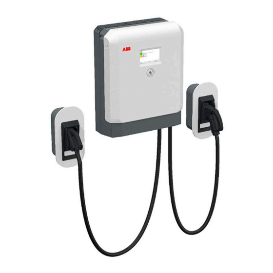
Terra 24 Wallbox
Wall & Pedestal Mount Fast Charger
Description
The UL certified Terra DC Wallbox is a compact 24 kW DC fast charger
perfect for commercial parking, auto dealerships, workplace facilities and
fleets. With its low-power, high-voltage architecture, the Terra DC Wallbox
can be installed at sites with defined or limited available power service –
while offering 920 VDC charging capability for every EV model.
Key Benefits and Features
•
DC output voltage range from 150 to 920 VDC
•
Single or dual outlet: CCS-1 and CHAdeMO
•
Daylight readable 7" full color touchscreen display
•
RFID reader
•
OCPP 1.6 and Smart Charging Profiles
•
Capability for remote services and updates
•
Compact robust all-weather enclosure for indoor and outdoor use
Specifications
•
Available with CCS1 or CCS2, Dual CCS1 or CCS2 and Dual CCS1 & CHAdeMO connectors
•
DIN70212 and ISO15118 protocols supported
•
IP54, NEMA 3S; indoor and outdoor
•
Dimensions (D x W x H): 11.8 in" x 23" (W) x 30.3" (H) / 300mm X 584mm X 770mm
•
Weight: 60kg / 132 lbs
Ordering Information
Configuration
Terra 24 - Single CCS
Terra 24 - CCS and CHAdeMO
* When ordering the ABB Terra series with CCS/CCS connectors (-CC), order the -CJ which is designed to
handle both CCS and CHAdeMo connector types.
SKU
ADC-24-480-C1-WC1R
ADC-24-480-C1CH-WC1R
The Terra 24 charger shown mounted
with accessory holsters
Advertisement
Table of Contents

Related Manuals for ABB Terra 24


Summary of Contents for ABB Terra 24
- Page 1 Ordering Information Configuration Terra 24 - Single CCS ADC-24-480-C1-WC1R Terra 24 - CCS and CHAdeMO ADC-24-480-C1CH-WC1R * When ordering the ABB Terra series with CCS/CCS connectors (-CC), order the -CJ which is designed to handle both CCS and CHAdeMo connector types.
- Page 2 Technical Specifications Configuration Voltage 1 Phase 208-240 ; 3 Phase 480V AC Input Power Connection 1 Phase L1, L2, GND; 3 Phase L1, L2, L3, N, GND Frequency 60Hz Recommended breaker 1 Phase125A ; 3 Phase 40A Power factor >0.96 THD - Current IEEE 519 Compliant;...
- Page 3 — MAN UAL : N ORT H A ME RI CA Terra DC Wallbox Single-phase Version Installation Manual Revision 2.6...
- Page 4 In no event shall ABB be liable for direct, indirect, special, incidental or consequential damages of any nature or kind aris- ing from the use of this document, nor shall ABB be liable for incidental or consequential damages arising from use of any software or hardware described in this document.
-
Page 5: Table Of Contents
Contents 1 Introduction............................... 6 Preface ................................. 6 Intended document users ..........................6 Terra DC Wallbox hardware ordering details ....................6 Signs ................................7 Owner responsibilities ........................ 8 1.4.1 Tilting and handling ........................8 1.4.2 Sharp edges ..........................9 1.4.3 Electric hazards ........................... 9 1.4.4 Installation safety ........................ - Page 6 Options............................23 5.3.1 Mounting the Terra DC Wallbox ......................... 23 Mounting the Terra DC Wallbox ....................23 5.4.1 Install cable gland(s) or connect conduit to the unit..............27 5.4.2 Connect cables ............................29 Connect PE of power cable ....................... 29 5.5.1 Connect power cable ........................
- Page 7 Grid provider Company responsible for the transportation and distri- bution of electricity. Human Machine Interface; the display/screen on the charger. ABB Network Operating Centre; remotely checks the correct functioning of the charger. Owner The legal owner of the charger. OCPP Open Charge Point Protocol.
-
Page 8: Introduction
Before installing the Terra DC Wallbox, read this installation guide carefully and attentively. Be sure to follow all instructions when installing the charger. ABB is not responsible for any damage caused by not following or incor- rectly executing the instructions described in this manual. -
Page 9: Signs
ABB6AGC107314 TWB UL 24 CJ 7M-7M-0-0 ABB6AGC109857 TWB UL 24 CJ 3M-7M-0-0 Optional connector holsters shown below may be purchased separately with the order code details shown below. Charging cable type ABB order code CCS-1 ABB6AGC076604 CCS-1 (*) ABB6AGC109619 CHAdeMO... -
Page 10: Owner Responsibilities
ABB’s warranty policy. Neither ABB nor its affiliates shall be liable to the purchaser of this product or third parties for damages, losses, costs or expenses incurred by purchaser or third parties as a result of: an accident, misuse or abuse of this product or unauthorized modifications, repairs or alterations to this product, or failure to strictly comply with ABB’s oper-... -
Page 11: Sharp Edges
2. Perform a voltage check to ensure electrical power is disconnected from the system. 3. Only ABB certified technicians should commission the Terra DC Wallbox. 4. When the system is in an open or dangerous condition, do not allow unqualified persons to go near it. Instruct and warn people about the po- tentially harmful high voltages. - Page 12 T ERR A D C WA LLB OX Description of the product Overview of the system 2.1.1 Complete overview Example of a complete installation Power distribution board of the owner Cables in conduit Terra DC Wallbox Parking space for charging Electric vehicle 2 023 -2 0 -06 10/ 40...
- Page 13 T ERR A D C WA LLB OX 2.1.2 External view Display / HMI Emergency stop button RFID card reader AC input connection point for Conduit DC Charging cable Air inlet Air outlet Optional Holster (purchased separately) Standard Holster (included) Optional charging cable Standard charging holster sold separate...
- Page 14 T ERR A D C WA LLB OX 2.1.3 Inside view AC input board D Cable gland for DC output(2x) CPI and IMI boards E Cable gland for AC input External Fan (2x) 2 023 -2 0 -06 1 2 /40...
- Page 15 Squid-4G or Sure Call device. Handheld mobile phones are not recommended for assessing signal strength since they are not reliable measuring devices. The DC Wallbox only supports SIM cards provided by ABB. Customer procured SIM cards are not supported. 3.1.2...
- Page 16 The allowable grid configurations are shown in the figures below. Please observe the 1-phase variant DC Wallbox supports two different grid configurations. For the 1-phase variant DC Wallbox, ABB recommends the electrical designer to consider power distribution phase balancing design requirements.
- Page 17 The 1-phase UL variant DC Wallbox requires Two (2) phase wires and One (1) wire for protective earth. (2W+G) All wires 1-phase variant of the DC Wallbox may connect directly to the ABB provided terminals. The integrity of the electrical grounding is essential. Ensure that the equipment grounding terminal is used in the device and an actual grounding conductor is installed to provide a path back to the source upstream panel.
- Page 18 The DC Wallbox does not have a hole designated for a conduit carrying only an ethernet cable to connect to. If ethernet cable solution is required for an installation, please contact your ABB sales contact person to re- view ethernet cable entry solutions.
- Page 19 T ERR A D C WA LLB OX 3.3.2 DC Wallbox position with respect to parking space The charging inlets on a vehicle can be located at different positions depending on the manufacturer. The most common vehicles have inlets located either on the front or in the back on either the left or right side. This makes some charger placements with respect to the parking space more favorable than others.
- Page 20 T ERR A D C WA LLB OX 3.3.3 Required space for installing and maintaining the DC Wallbox The Terra DC Wallbox requires a minimum space of 36” x 48”. This space is calculated as follows: - Charger size (H x W x D): 30.3 x 23 x 11.8 in - Bottom side 23.6”...
- Page 21 T ERR A D C WA LLB OX 3.3.4 Ventilation and airflow required for the DC Wallbox The Terra DC Wallbox has an air inlet on the bottom side and an outlet on the top side. NOTICE Free air flow If necessary, take precautions to prevent snow or objects from blocking the inlets and outlets.
- Page 22 The preferred method of communication is the wireless 4G modem integrated into the charger. A customer SIM card is not required. A subscription for the SIM card is provided by ABB for select countries. If there is no wireless signal available, a standard wired internet connection is required. (Reference Section 3.1, 3.2.5 and 3.2.6 for wiring and connection methods)
- Page 23 2. Make a notation on the delivery receipt and inspect cabinet for damage. 3. If damage is discovered, leave cabinet in original package and request immediate inspection from carrier within 3 days of delivery. 4. Contact your local ABB office. Unpacking the charging and mounting preparations 5.2.1 Unpacking The packaging of the Terra DC Wallbox can be removed without the use of tools.
- Page 24 T ERR A D C WA LLB OX Bottom Cover Grill 1. Remove the plastic protection profiles. 2. Remove the bottom air grate grill and the lower frontal cover. 3. Remove the wall frame. 4. Remove the Terra DC Wallbox. (USE CAUTION TO NOT DAMAGE THE E-STOP BUTTON ON THE SIDE OF THE ENCLOSURE) 5.
-
Page 25: Options
T ERR A D C WA LLB OX Move cabinet to position 5.3.1 Options A properly rated lifting devices should be used to move the Terra DC Wallbox from the delivery truck to the installation location. DANGER Hazardous voltage Ensure the product’s power supply group main switch is set to the OFF po- sition. - Page 26 T ERR A D C WA LLB OX 1. Carefully lower the Terra DC Wallbox onto its location. 2. Ensure cable(s) are not entrapped. 3. Place the wall frame in the correct position on the wall bearing by aligning the four holes of the charger with the corresponding holes on the wall bearing.
- Page 27 T ERR A D C WA LLB OX 6. Tighten the two M5 bolts on the lower side of the unit. Pay attention to the internal fan power supply cable. CAUTION: DO NOT SET SMALL OBJECTS ON TOP MESH COVER, ITEMS MAY FALL INTO THE COOLING FINS OR FAN COMPONENTS.
- Page 28 T ERR A D C WA LLB OX 9. AFTER the completing wiring terminations, take the bottom cover grill and put it on the lower side of the unit and fix it by tightening two screws as shown in the following picture. Please note the 3-phase and 1-phase versions have a slightly different bottom grill assembly 10.
-
Page 29: Install Cable Gland(S) Or Connect Conduit To The Unit
T ERR A D C WA LLB OX 12. Place the central cover on the unit and secure it in place by tightening the two screws located on the left and right side of the cover. Center the bottom pins, rotate the cover, and tighten the 2 lateral screws. - Page 30 T ERR A D C WA LLB OX 2. Push the cables back through the gland plate, until sufficient cable length is left to reach the cable termi- nals. Ensure the PE cable is longer than the other cables. Conduit Installation 1.25“...
-
Page 31: Connect Cables
T ERR A D C WA LLB OX Connect cables 5.5.1 Connect PE of power cable Preconditions: • Tools: Wire stripper pliers; wire-end lug pliers; wire-end lug. DANGER Hazardous voltage Make sure that the main switch of the power supply group for the product is set to the OFF position. -
Page 32: Instruction For Mounting The Dc Wallbox Gun Holders
T ERR A D C WA LLB OX • From left to right for the 1-phase unit (as showed in the following picture): PE- terminal block green/yellow, L2 - terminal block grey, L1 - terminal block grey L2 L1 208/240V 1-phase terminal layout 12. -
Page 33: Mounting Instructions
T ERR A D C WA LLB OX 5.6.3 Mounting instructions The gun holders described above are intended for a very simple installation. Standard gun holder is provided with 3 holes for wall hooking while optional one is provided with a wall mounted hooking bar (10 in Fig.3) to be mounted to wall. - Page 34 T ERR A D C WA LLB OX 2 023 -2 0 -06 3 2/ 40...
-
Page 35: Commissioning
A certified service engineer from the ABB Service department or a trained engineer by ABB is required to perform the commissioning. During this commissioning, the safety and the functioning of the charger will be tested. -
Page 36: Maintenance And Cleaning Of The Cabinet
T ERR A D C WA LLB OX Maintenance and Cleaning of the cabinet Recommended Periodic maintenance A. Following procedures, de-energize unit, open cover, inspect air filter, clean NFPA-70e or replace as needed. B. Check input connections and terminations for proper toque values C. -
Page 37: Technical Data
T ERR A D C WA LLB OX Technical Data Electrical data AC Input AC input voltage range 208 - 240 V +/- 10% (60Hz) AC input power connection 1-phase, 208-240 V : L1, L2, GND Maximum rated input current at nominal voltage 100 A Recommended upstream overcurrent protection 125 A... -
Page 38: Mechanical Data
T ERR A D C WA LLB OX Mechanical data Mechanical data Dimensions (H x W x D) 770 mm x 585 mm x 300 mm / 30.32” x 23.03” x 11.81” Weight 70 kg / 154.32lbs Volume 0,135 m3 Dimensions including packaging (H X W x D) 650 mm x 1200 mm x 800 mm /25.6”... -
Page 39: Contact Information
In case they cannot solve the prob- lem, they will contact the second line Service organization. ABB in your country Please contact ABB in your country for sales, delivery and service information. ABB EV Infrastructure USA ABB Inc. -
Page 40: Appendix A - Mounting Points
T ERR A D C WA LLB OX Appendix A – Mounting points 10.1 Terra DC Wallbox Charger wall mounting 2 023 -2 0 -06 38 /40... -
Page 41: Appendix B - Disposal Instruction
T ERR A D C WA LLB OX Appendix B - Disposal instruction 11.1 Directive on Waste Electrical and Electronic Equipment (WEEE – 2012/19/EU) 2 023 -2 0 -06 39/ 40... -
Page 42: Appendix C - Pedestal Requirements
T ERR A D C WA LLB OX Appendix C – Pedestal requirements Any pedestal solution designed for Terra DC Wallbox needs to fulfill the specific ISO standards for civil con- structions (note: specific local regulations may apply). Additionally, whereas no specific constraint is provided by local regulations, the minimum set of require- ments necessary to provide a safe installation are listed in the table below to be verified in the temperature range between -50°C - +60°C: Minimum Wind load resistance... - Page 43 — IN STA LL AT IO N M AN U A L NO RTH A M ER IC A Terra DC Wallbox North America Three-phase Version Revision 2.9...
- Page 44 ABB products. The presence of any such description of a standard or reference to a standard is not a representation that all of the ABB products referenced in this document support all of the features of the described or referenced standard. In order to determine the specific features supported by a particular ABB product, the reader should consult the product specifications for the particular ABB product.
- Page 45 All rights reserved. ATTENTION: YOU MUST CONNECT L1, L2, L3, N AND PE WIRES BEFORE POWERING UP THIS CHARGER. FAILURE TO DO SO WILL CAUSE DAMAGE TO THE CHARGER AND VOID WARRNTY L1, L2, L3, N AND PE LABELS ARE ON THE TERMINAL BLOCK...
- Page 46 Contents 1 Introduction ............................7 Preface............................7 Intended document users ......................7 Terra DC Wallbox hardware ordering details ................. 7 Signs .............................. 8 1.4.1 Owner responsibilities ....................9 1.4.2 Tilting and handling ......................9 1.4.3 Sharp edges ........................9 1.4.4 Electric hazards ......................
- Page 47 5.3.1 Options ......................... 23 Mounting the Terra DC Wallbox ....................23 5.4.1 Mounting the Terra DC Wallbox ................... 24 5.4.2 Install cable gland(s) or connect conduit to the unit............. 27 Connect cables ..........................29 5.5.1 Connect PE of power cable ..................29 5.5.2 Connect power cable ....................
- Page 48 Grid provider Company responsible for the transportation and distribution of electricity. Human Machine Interface; the display/screen on the charger. ABB Network Operating Centre; remotely checks the correct functioning of the charger. Owner The legal owner of the charger. OCPP Open Charge Point Protocol. Open standard for communication with charge stations.
-
Page 49: Introduction
Before installing the Terra DC Wallbox, read this installation guide carefully and attentively. Be sure to follow all instructions when installing the charger. ABB is not responsible for any damage caused by not following or incorrectly executing the instructions described in this manual. -
Page 50: Signs
T ERR A D C WA LLB OX Optional connector holsters shown below may be purchased separately with the order code details shown below. Charging cable type ABB order code CCS-1 ABB6AGC076604 CCS-1 (*) ABB6AGC109619 CHAdeMO ABB6AGC076601 (*) CCS-1 optional holster to be use in combination with products:... -
Page 51: Owner Responsibilities
ABB’s warranty policy. Neither ABB nor its affiliates shall be liable to the purchaser of this product or third parties for damages, losses, costs or expenses incurred by purchaser or third parties as a result of: an accident, misuse or abuse of this product or unauthorized modifications, repairs or alterations to this product, or failure to strictly comply with ABB’s operating and maintenance instructions. -
Page 52: Installation Safety
NFPA-70e. 2. Perform a voltage check to ensure electrical power is disconnected from the system. 3. Only ABB certified technicians should commission the Terra DC Wallbox. 4. When the system is in an open or dangerous condition, do not allow unqualified persons to go near it. -
Page 53: Description Of The Product
T ERR A D C WA LLB OX Description of the product Overview of the system Complete overview 2.1.1 Example of a complete installation Power distribution board of the owner Cables in conduit Terra DC Wallbox Parking space for charging Electric vehicle 2 023 -06 -20 1 1/39... -
Page 54: External View
T ERR A D C WA LLB OX External view 2.1.2 Display / HMI Emergency stop button RFID card reader AC input connection point for Conduit DC Charging cable Air inlet Air outlet Optional Holster (purchased separately) Standard Holster (included) Optional charging cable Standard charging holster sold separate... -
Page 55: Inside View
T ERR A D C WA LLB OX Inside view 2.1.3 AC input board D Cable gland for DC output(2x) CPI and IMI boards E Cable gland for AC input External Fan (2x) 2 023 -06 -20 13 /39... -
Page 56: Installation Planning And Design
Squid-4G or Sure Call device. Handheld mobile phones are not recom- mended for assessing signal strength since they are not reliable measuring devices. The DC Wallbox only supports SIM cards provided by ABB. Customer procured SIM cards are not supported. -
Page 57: Electrical Requirements
If ABB is contracted to perform the DC Wallbox commissioning, ABB observes the right to charge additional money for more than one site visit required for the commissioning due to an initial, improper installation of the DC Wallbox. -
Page 58: Overcurrent Protection Device
The 3-phase UL variant DC Wallbox requires Three (3) phase wires, One (1) neutral wire, and One (1) wire for protective earth. (3W+N+G) All wires for 3-phase variants of the DC Wallbox may connect directly to the ABB provided termi- nals, with exception to the protective earth wire. The protective earth wire requires for the installer to crimp a terminal onto it using the terminal manufacturer’s recommended crimp procedure and... -
Page 59: Conduit For Ethernet Cable
The DC Wallbox does not have a hole designated for a conduit carrying only an ethernet cable to connect to. If ethernet cable solution is required for an installation, please contact your ABB sales contact person to review ethernet cable entry solutions. -
Page 60: Dc Wallbox Position With Respect To Parking Space
T ERR A D C WA LLB OX DC Wallbox position with respect to parking space 3.3.2 The charging inlets on a vehicle can be located at different positions depending on the manufac- turer. The most common vehicles have inlets located either on the front or in the back on either the left or right side. -
Page 61: Required Space For Installing And Maintaining The Dc Wallbox
T ERR A D C WA LLB OX Required space for installing and maintaining the DC Wallbox 3.3.3 The Terra DC Wallbox requires a minimum space of 36” x 48”. This space is calculated as follows: - Charger size (H x W x D): 30.3 x 23 x 11.8 in - Bottom side 23.6”... -
Page 62: Considerations For Where To Position Dc Wallbox Vertically
The Terra DC Wallbox can also be mounted on a pedestal. In order to achieve a safe installation, the minimum set of requirements are included in Appendix C – Pedestal requirements). For the ABB pedestal solution, contact your local ABB sales representative. 2 023 -06 -20... -
Page 63: Power Feed
Internet connection The preferred method of communication is the wireless 4G modem integrated into the charger. A customer SIM card is not required. A subscription for the SIM card is provided by ABB for select countries. If there is no wireless signal available, a standard wired internet connection is required. (Reference Section 3.1, 3.2.5 and 3.2.6 for wiring and connection methods) -
Page 64: Unpacking The Charging And Mounting Preparations
2. Make a notation on the delivery receipt and inspect cabinet for damage. 3. If damage is discovered, leave cabinet in original package and request immediate inspec- tion from carrier within 3 days of delivery. 4. Contact your local ABB office. Unpacking the charging and mounting preparations Unpacking 5.2.1... -
Page 65: Move Cabinet To Position
T ERR A D C WA LLB OX Mounting preparations 5.2.2 Unpack the IP BOX and verify all the following items are present: • Wall frame • Frontal cover • Bottom grid cover Move cabinet to position Options 5.3.1 A properly rated lifting devices should be used to move the Terra DC Wallbox from the delivery truck to the installation location. -
Page 66: Mounting The Terra Dc Wallbox
T ERR A D C WA LLB OX Mounting the Terra DC Wallbox 5.4.1 NOTICE The minimum number of people required to lift and install the Terra DC Wallbox must be determined based on the relevant local regulation with taking into account the maximum allowed weight per person as well as the usage of the appropriate and suitable lifting equipment. - Page 67 T ERR A D C WA LLB OX 6. Tighten the two M5 bolts on the lower side of the unit. Pay attention to the internal fan power supply cable. CAUTION: DO NOT SET SMALL OBJECTS ON TOP MESH COVER, ITEMS MAY FALL INTO THE COOLING FINS OR FAN COMPONENTS.
- Page 68 T ERR A D C WA LLB OX 9. AFTER the completing wiring terminations, take the bottom cover grill and put it on the lower side of the unit and fix it by tightening two screws as shown in the following picture. Please note the 3-phase and 1-phase versions have a slightly different bottom grill assembly 10.
-
Page 69: Install Cable Gland(S) Or Connect Conduit To The Unit
T ERR A D C WA LLB OX 12. Place the central cover on the unit and secure it in place by tightening the two screws located on the left and right side of the cover. Center the bottom pins, rotate the cover, and tighten the 2 lateral screws. - Page 70 T ERR A D C WA LLB OX NOTE 1: For 3-phase versions a ferrite core is provided with the Wallbox (plastic bag within the package or strapped to the CCS-1 cable) and needs to be installed in commissioning phase. The Ferrite needs to be inserted in the AC in cable and located in the screw cable cover (see picture above, left).
-
Page 71: Connect Cables
T ERR A D C WA LLB OX Connect cables Connect PE of power cable 5.5.1 Preconditions: • Tools: Wire stripper pliers; wire-end lug pliers; wire-end lug. DANGER Hazardous voltage Make sure that the main switch of the power supply group for the product is set to the OFF position. -
Page 72: Instruction For Mounting The Dc Wallbox Gun Holders
T ERR A D C WA LLB OX 11. Attach the four wires on to their connectors as indicated on the label on the relative terminal block (see the following picture as example). • From left to right for the 3-phase unit (as showed in the following picture): N - terminal block blue, L1 - terminal block grey, L2 - terminal block grey, L3 - terminal block grey 12. - Page 73 T ERR A D C WA LLB OX Figure 3: Terra DC wallbox optional gun Figure 4: Terra DC holder. wallbox optional Gun holder; front and side view. 2 023 -06 -20 31 /39...
-
Page 74: Commissioning
A certified service engineer from the ABB Service department or a trained engineer by ABB is re- quired to perform the commissioning. During this commissioning, the safety and the functioning of the charger will be tested. -
Page 75: Maintenance And Cleaning Of The Cabinet
T ERR A D C WA LLB OX Maintenance and Cleaning of the cabinet Recommended Periodic maintenance A. Following NFPA-70e procedures, de-energize unit, open cover, inspect air filter, clean or replace as needed. B. Check input connections and terminations for proper toque values C. -
Page 76: Technical Data
T ERR A D C WA LLB OX Technical Data Electrical data AC Input AC input voltage range 480 V +/- 10% (60Hz) AC input power connection 3-phase, 480Y/277 V : L1, L2, L3, N, GND Nominal input current and input power rating 32 A / 26.6 kVA at 480V, peak input current: 35 A / 26.6 kVA at 432V Recommended upstream overcurrent... -
Page 77: Mechanical Data
T ERR A D C WA LLB OX Mechanical data Mechanical data Dimensions (H x W x D) 770 mm x 585 mm x 300 mm / 30.32” x 23.03” x 11.81” Weight 70 kg / 154.32lbs Volume 0,135 m Dimensions including packaging (H X W 650 mm x 1200 mm x 800 mm /25.6”... -
Page 78: Contact Information
In case they cannot solve the problem, they will contact the second line Service organization. ABB in your country Please contact ABB in your country for sales, delivery and service information. ABB EV Infrastructure USA ABB Inc. 950 E Elliott Rd... -
Page 79: Appendix A - Mounting Points
T ERR A D C WA LLB OX Appendix A – Mounting points Terra DC Wallbox Charger wall mounting 10.1 2 023 -06 -20 37/39... -
Page 80: Appendix B - Disposal Instruction
T ERR A D C WA LLB OX Appendix B - Disposal instruction Directive on Waste Electrical and Electronic Equipment (WEEE – 11.1 2012/19/EU) 2 023 -06 -20 38 /39... -
Page 81: Appendix C - Pedestal Requirements
T ERR A D C WA LLB OX Appendix C – Pedestal requirements Any pedestal solution designed for Terra DC Wallbox needs to fulfill the specific ISO standards for civil constructions (note: specific local regulations may apply). Additionally, whereas no specific constraint is provided by local regulations, the minimum set of re- quirements necessary to provide a safe installation are listed in the table below to be verified in the temperature range between -50°C - +60°C: Minimum Wind load resistance...
Need help?
Do you have a question about the Terra 24 and is the answer not in the manual?
Questions and answers