Table of Contents
Advertisement
Quick Links
Getting started with the X-NUCLEO-IDW04A1 Wi-Fi expansion
Introduction
This document provides detailed hardware requirements and board connections for the X-NUCLEO-
IDW04A1 Wi-Fi expansion board based on SPWF04SA Serial-to-Wi-Fi modules, to allow expansion of
the STM32 Nucleo boards. The SPWF04SA module is FCC (FCC ID: S9NSPWFS04), IC certified (IC:
8976C-SPWFS04) and CE certified and includes an STM32 MCU, a low-power 2.4 GHz IEEE 802.11
b/g/n transceiver with integrated power amplifier and power management, and an SMD antenna.
The X-NUCLEO-IDW04A1 can be plugged onto STM32 Nucleo boards via the Arduino™ UNO R3
connector (ST morpho connector compatibility is also available). Therefore, different expansion boards
can easily be stacked on the X-NUCLEO-IDW04A1 board, allowing evaluation of Wi-Fi connectivity
together with several devices in different application scenarios.
The expansion board features:
Onboard SPWF04SA module (order code: SPWF04SA) based on the STM32 MCU and a low
power Wi-Fi b/g/n transceiver SoC
USART or SPI configurable connections
Jumpers to drive the SPWF04SA module RESET and low power capabilities
Push button to explore Wi-Fi protected setup feature
Connectors for SPWF04SA module GPIOs (user software dependent)
July 2017
Arrow.com.
Downloaded from
board based on SPWF04SA module for STM32 Nucleo
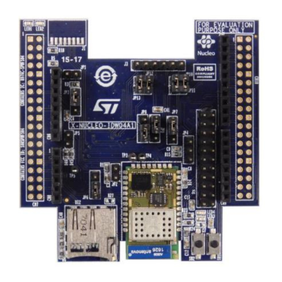
Figure 1: X-NUCLEO-IDW04A1 expansion board
DocID030409 Rev 2
UM2183
User manual
1/24
www.st.com
Advertisement
Table of Contents

Related Manuals for ST X-NUCLEO-IDW04A1


Summary of Contents for ST X-NUCLEO-IDW04A1
-
Page 1: Figure 1: X-Nucleo-Idw04A1 Expansion Board
8976C-SPWFS04) and CE certified and includes an STM32 MCU, a low-power 2.4 GHz IEEE 802.11 b/g/n transceiver with integrated power amplifier and power management, and an SMD antenna. The X-NUCLEO-IDW04A1 can be plugged onto STM32 Nucleo boards via the Arduino™ UNO R3 connector (ST morpho connector compatibility is also available). Therefore, different expansion boards can easily be stacked on the X-NUCLEO-IDW04A1 board, allowing evaluation of Wi-Fi connectivity together with several devices in different application scenarios. -
Page 2: Table Of Contents
Hardware requirements ..............5 System requirements ................ 5 Board setup ..................6 Hardware description ..............8 X-NUCLEO-IDW04A1 expansion board for STM32 Nucleo ....8 STM32 Nucleo connections ............12 UART/SPI interface and GPIO connection options ......12 Current measurement ..............13 X-NUCLEO-IDW04A1 component placement details ...... - Page 3 List of tables List of tables Table 1: UART/SPI 0 Ω resistor configuration .................... 6 Table 2: STM32 Nucleo board/X-NUCLEO-IDW04A1 interconnection (ST morpho connector: CN7) ..9 Table 3: STM32 Nucleo board/X-NUCLEO-IDW04A1 interconnection (ST morpho connector: CN7): hardware ..............................10 Table 4: STM32 Nucleo board/X-NUCLEO-IDW04A1 interconnection (ST morpho connector: CN10) ..
- Page 4 UM2183 List of figures Figure 1: X-NUCLEO-IDW04A1 expansion board ..................1 Figure 2: X-NUCLEO-IDW04A1 expansion board connected to an STM32 Nucleo board ......5 Figure 3: UART default jumper configuration ..................... 6 Figure 4: SPI jumper configuration ......................6 Figure 5: SPWF04SA module to STM32 Nucleo connector scheme ............9 Figure 6: X-NUCLEO-IDW04A1 expansion board component placement details: top ......
-
Page 5: Getting Started
Getting started Hardware requirements The X-NUCLEO-IDW04A1 is an expansion board for the STM32 Nucleo boards. To function correctly, it must be plugged on a STM32 Nucleo board through the Arduino™ UNO R3 connectors as shown in the figure below. Information on STM32 Nucleo is available at http://www.st.com/stm32nucleo. -
Page 6: Board Setup
JP13 (refer to the following table for a full 0 Ω resistor configuration). Table 1: UART/SPI 0 Ω resistor configuration Peripheral UART Plug the X-NUCLEO-IDW04A1 on the STM32 Nucleo board, as shown in Figure 2: "X-NUCLEO-IDW04A1 expansion board connected to an STM32 Nucleo board" 6/24 DocID030409 Rev 2 Arrow.com. - Page 7 UM2183 Getting started Power the STM32 Nucleo development board through the Mini-B USB cable. Program the STM32 Nucleo development board using the sample firmware provided. Reset the STM32 Nucleo development board MCU through the onboard Reset button. The board setup is ready to evaluate Wi-Fi connectivity. DocID030409 Rev 2 7/24 Arrow.com.
-
Page 8: Hardware Description
Table 6: "STM32 Nucleo board/X-NUCLEO-IDW04A1 interconnection (Arduino UNO R3 connector: CN8 - analog)", Table 7: "STM32 Nucleo board/X-NUCLEO-IDW04A1 interconnection (Arduino UNO R3 connector: CN5 - digital)" Table 8: "STM32 Nucleo board/X-NUCLEO-IDW04A1 interconnection (Arduino UNO R3 connector: CN9 - digital)"). -
Page 9: Figure 5: Spwf04Sa Module To Stm32 Nucleo Connector Scheme
UM2183 Hardware description Figure 5: SPWF04SA module to STM32 Nucleo connector scheme Table 2: STM32 Nucleo board/X-NUCLEO-IDW04A1 interconnection (ST morpho connector: CN7) CN7 odd - UNUSED CN7 even Name MCU name MCU name +3V3 RESET +3V3 +5 V DocID030409 Rev 2 9/24 Arrow.com. -
Page 10: Table 2: Stm32 Nucleo Board/X-Nucleo-Idw04A1 Interconnection (St Morpho Connector: Cn7)
Hardware description UM2183 Table 3: STM32 Nucleo board/X-NUCLEO-IDW04A1 interconnection (ST morpho connector: CN7): hardware CN7 odd CN7 even USART_CTS USART_RTS SPI_IRQ WAKEUP SPI_CS PC1 (PB9 SPI_CS PC0 (PB8 Notes: Disabled by 0 Ω default configuration Table 4: STM32 Nucleo board/X-NUCLEO-IDW04A1 interconnection (ST morpho connector:... -
Page 11: Table 7: Stm32 Nucleo Board/X-Nucleo-Idw04A1 Interconnection
UM2183 Hardware description Table 5: STM32 Nucleo board/X-NUCLEO-IDW04A1 interconnection (Arduino UNO R3 connector: CN6 - power) Signal name IOREF RESET +3V3 +5 V GND 1 GND 2 MCU name +3V3 RESET +3V3 +5 V Table 6: STM32 Nucleo board/X-NUCLEO-IDW04A1 interconnection (Arduino UNO R3... -
Page 12: Stm32 Nucleo Connections
UM2183 STM32 Nucleo connections The X-NUCLEO-IDW04A1 expansion board is designed to be plugged directly on the STM32 Nucleo board connectors. The X-NUCLEO-IDW04A1 is configured by default to be compatible with as many STM32 Nucleo boards as possible. It may also be configured, via jumper or resistor placement, to use different I/O configurations to match specific customer targets. -
Page 13: Current Measurement
UM2183 Hardware description Table 10: SPWF04SA module SPI interface with STM32 Nucleo board SPWF04SA STM32 pin Placement Pin/Signal CN10 – pin 13 6/MISO PA6 (PB14 CN5 – Pin 1 CN10 – pin 19 CN5 – Pin 2 To use this connection: mount R28 and remove R13 (Default) 7/GPIO9 CN7 –... -
Page 14: X-Nucleo-Idw04A1 Component Placement Details
Hardware description UM2183 X-NUCLEO-IDW04A1 component placement details Figure 6: X-NUCLEO-IDW04A1 expansion board component placement details: top 14/24 DocID030409 Rev 2 Arrow.com. Arrow.com. Arrow.com. Arrow.com. Arrow.com. Arrow.com. Arrow.com. Arrow.com. Arrow.com. Arrow.com. Arrow.com. Arrow.com. Arrow.com. Arrow.com. Downloaded from Downloaded from Downloaded from... -
Page 15: Figure 7: X-Nucleo-Idw04A1 Expansion Board Component Placement Details: Bottom
UM2183 Hardware description Figure 7: X-NUCLEO-IDW04A1 expansion board component placement details: bottom DocID030409 Rev 2 15/24 Arrow.com. Arrow.com. Arrow.com. Arrow.com. Arrow.com. Arrow.com. Arrow.com. Arrow.com. Arrow.com. Arrow.com. Arrow.com. Arrow.com. Arrow.com. Arrow.com. Arrow.com. Downloaded from Downloaded from Downloaded from Downloaded from Downloaded from... -
Page 16: Component Description
Typ. 3.3 V User push-buttons and LEDs The X-NUCLEO-IDW04A1 expansion board has two push-buttons and four LEDs to control certain I/O signals and transmit SPWF04SA module status information. The associated hardware and firmware functions are shown in the following table. -
Page 17: Table 13: X-Nucleo-Idw04A1 Board User Mode Configuration Settings
UM2183 Component description Table 13: X-NUCLEO-IDW04A1 board user mode configuration settings User mode No external host Remove Remove Remove Remove Remove VCOM UART Remove VCOM SPI Insert DocID030409 Rev 2 17/24 Arrow.com. Arrow.com. Arrow.com. Arrow.com. Arrow.com. Arrow.com. Arrow.com. Arrow.com. Arrow.com. -
Page 18: Radio Certification
The X-NUCLEO-IDW04A1 contains the IC certified SPWF04SA module (IC: 8976C- SPWFS04) Formal notices required by the ETSI (CE) -
Page 19: Bill Of Materials
Bill of materials UM2183 Bill of materials Table 14: X-NUCLEO-IDW04A1 bill of materials Item Q.ty Ref. Part/Value Description Manufacturer Order code C1, C2, C3, C6, C7, C8, 100 nF,16 GRM188R71C104KA0 C9, C11, V, 0603, Capacitor MURATA C12, C40, 0603 MOUNTED... - Page 20 Bill of materials UM2183 Item Q.ty Ref. Part/Value Description Manufacturer Order code 100 Ω Resistor ±5%,0603 R18, 270 Ω ±5%, R22, Resistor 0603 470 Ω ±5%, Resistor 0603 4.7 KΩ R1, R45 Resistor ±5%,0603 R2, R4, 10 KΩ Resistor R6, R24 ±5%,0603 R46, 47 KΩ...
- Page 21 Bill of materials UM2183 Item Q.ty Ref. Part/Value Description Manufacturer Order code MOUNTED (I.C. Serial USON8 Flash 8Mbit MACRONIX MX25L8006EZUI-12G 2.7-3.6 V p/n MX25L8006EZ UI-12G) Micro SD Socket p/n ATTEND 112A-TAAR-R03 112A-TAAR- TP3, TP4, PIN 1 pole SPWF04SA MT4162LC6F Wi-Fi Module DocID030409 Rev 2 21/24 Arrow.com.
-
Page 22: Schematic Diagrams
Schematic diagrams UM2183 Schematic diagrams Figure 8: X-NUCLEO-IDW04A1 circuit schematic GPIO17 GPIO18 GPIO15_X GPIO16 GPIO13_X GPIO14_X GPIO11_X GPIO12_X GPIO12_X GPIO9 GPIO10 GPIO8 GPIO7_X GPIO6 GPIO4 GPIO5 GPIO3 GPIO2_X GPIO11_X GPIO1_X GPIO0 RXDCP2102 TXDCP2102 GPIO5 CTSCP2102 GPIO1_X RTSCP2102 GPIO7_X GPIO3 GPIO18... -
Page 23: Revision History
Figure 1: "X-NUCLEO-IDW04A1 expansion board". Updated Figure 3: "UART default jumper configuration" Table 1: "UART/SPI 0 Ω resistor configuration". 04-Jul-2017 Updated Table 13: "X-NUCLEO-IDW04A1 board user mode configuration settings". Minor text changes. DocID030409 Rev 2 23/24 Arrow.com. Arrow.com. Arrow.com. Arrow.com. - Page 24 ST products and/or to this document at any time without notice. Purchasers should obtain the latest relevant information on ST products before placing orders. ST products are sold pursuant to ST’s terms and conditions of sale in place at the time of order acknowledgement.
Need help?
Do you have a question about the X-NUCLEO-IDW04A1 and is the answer not in the manual?
Questions and answers