ETC Echoflex ELED1H Installation Manual
Fixture controller
Hide thumbs
Also See for Echoflex ELED1H:
- Installation manual (9 pages) ,
- Configuration manual (26 pages)
Table of Contents
Advertisement
Quick Links
Installation Guide
ELED1H Fixture Controller
IMPORTANT SAFEGUARDS
READ AND FOLLOW ALL
SAFETY INSTRUCTIONS
THESE INSTRUCTIONS
CAUTION - This equipment has more than
•
one power supply connection point. To reduce the
risk of electric shock disconnect both the branch
circuit-breakers or fuses and emergency power
supplies before servicing.
•
CAUTION – Risk of Electric shock hazard. The
controller uses high voltage and should only be in-
stalled by qualified personnel in accordance with
National Electrical Code and any local regulations.
•
CAUTION - To avoid electrical overload, total
connected load should not exceed output rating.
•
This product is suitable for use in dry locations
where the ambient temperature is -5°C to +50°C.
•
Do not use outdoors.
•
Do not mount near gas or electric heaters
•
Equipment should be mounted in locations
and at heights where it will not be subjected to
SAVE
ELED1H Installation Guide
Page 1
Advertisement
Table of Contents

Related Manuals for ETC Echoflex ELED1H


Summary of Contents for ETC Echoflex ELED1H
- Page 1 Installation Guide ELED1H Fixture Controller IMPORTANT SAFEGUARDS READ AND FOLLOW ALL SAFETY INSTRUCTIONS SAVE THESE INSTRUCTIONS CAUTION - This equipment has more than • one power supply connection point. To reduce the risk of electric shock disconnect both the branch circuit-breakers or fuses and emergency power supplies before servicing.
- Page 2 tampering by unauthorized personnel. • accessory equipment recommended by the manufacturer may cause an unsafe condition. • Do not use this equipment for other than its in- tended use. • Servicing should be performed by qualified ser- vice personnel. • Pollution Degree:2.
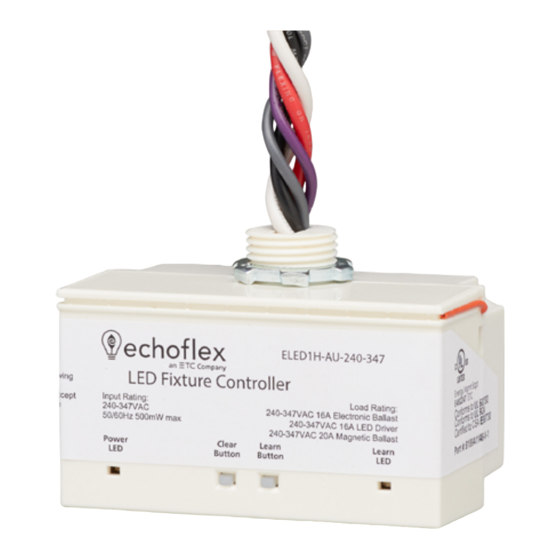
- Page 3 Overview This guide covers the LED Fixture Controller, model number ELED1H-AU with input voltage of 240-347VAC. The ELED1H is equipped with a 902 MHz radio. The box contents includes the controller and installation guide. A programming guide with detailed features of the controller is available for download on www.echoflexsolutions.com.
- Page 4 Installing the Controller For best results mount the controller on the outside of the electrical box either directly at the electrical load or before the load in the circuit. Review these instructions completely before installing the controller. 1. Locate the circuit breaker panel and terminate power to the circuit. 2.
- Page 5 Electrical Terminations The controller has an external orange antenna wire. Do not cut, cap or connect this wire. Power to the controller is connected between the White (Neutral) and the Black (240-347 VAC) Line power. The Class 1 power limited dimming lines (violet and gray wires) can be used to provide 0-10V control of a dimming ballast or LED driver.
- Page 6 Linking the First Switch e this method to link the first switch. Use the learn button to link additional devices. 1. If the controller already has a sensor linked, press the TEACH button on the linked sensor and proceed to step 2 within 60 seconds. 2.
- Page 7 LED Blink Codes and Operation The tables below describe the LED activity and associated mode of the controller. If the controller was factory pre-commissioned, upon power up it will immediately begin blinking the red POWER LED based on the type and count of linked devices.
- Page 8 Listings & Regulatory Statements UL Listed Component Certified UL Standard 924 Certified UL Standard 60730 Certified CAN/CSA Std E60730 UL 2043 Plenum rated California Energy Commission Title 24 - CEC Washington State Energy Code - WSEC ANSI / ASHRAE / IES Standard 90.1 International Energy Conservation Code - IECC New York City Energy Conservation Code - NYCECC FCC Part 15.231 Contains FCC ID: SZV-STM300U...
Need help?
Do you have a question about the Echoflex ELED1H and is the answer not in the manual?
Questions and answers