Perkins 854E-E34TA Systems Operation Testing And Adjusting
Industrial engines
Hide thumbs
Also See for 854E-E34TA:
- Operation and maintenance manual (119 pages) ,
- Troubleshooting manual (252 pages)

Related Manuals for Perkins 854E-E34TA


Summary of Contents for Perkins 854E-E34TA
- Page 1 UENR0623-01 March 2013 Systems Operation Testing and Adjusting 854E-E34TA and 854F-E34T Industrial Engines JR (Engine) JS (Engine) JT (Engine) This document is printed from SPI². Not for RESALE...
- Page 2 These changes can affect the service that is given to the product. Obtain the complete and most current information before you start any job. Perkins dealers or Perkins distributors have the most current information available. When replacement parts are required for this product Perkins recommends using Perkins replacement parts.
-
Page 3: Table Of Contents
UENR0623 Table of Contents Table of Contents Cooling System - Check ......... 70 Cooling System - Inspect........ 70 Cooling System - Test........71 Systems Operation Section Engine Oil Cooler - Inspect......72 Water Temperature Regulator - Test....73 General Information Water Pump - Inspect .... -
Page 4: Systems Operation Section
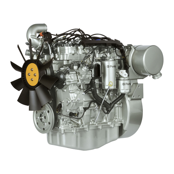
UENR0623 General Information Systems Operation Section General Information i05241818 Introduction The following model views show a typical industrial engine. Due to individual applications, your engine may appear different from the illustrations. Illustration 1 g02317613 Typical example (1) Clean Emissions Module (CEM) (4) Air inlet connection from charge cooler (2) Oil gauge (Dipstick) (5) Coolant outlet connection... - Page 5 (21) Primary fuel filter (18) Secondary fuel filter (22) Fuel injection pump Note: The primary fuel filter (21) may be supplied The 854E-E34TA and 854F-E34T diesel engines are electronically controlled. The 854E-E34TA and 854F- loose. E34T engines have an Electronic Control Module...
- Page 6 Control Module (ECM) to control the engine speed. Each cylinder has a piston cooling jet that is installed For the specifications of the 854E-E34TA and 854F- in the cylinder block. The piston cooling jet sprays E34T engines, refer to the Specifications, “Engine engine oil onto the inner surface of the piston in order Design”.
-
Page 7: Engine Operation
UENR0623 Engine Operation Engine Operation The cylinders are honed to a specially controlled finish in order to ensure long life and low oil consumption. The cylinder block has five main bearings which support the crankshaft. Thrust washers are installed i04169549 on both sides of number 3 main bearing in order to control the end play of the crankshaft. - Page 8 UENR0623 Engine Operation The port for the inlet valve is on the top of the cylinder The connecting rods (4) are machined from forged head. The port for the exhaust valve is on the right steel. The connecting rods have bearing caps (6) that side of the cylinder head.
- Page 9 UENR0623 Engine Operation Lip type seals are used on both the front of the The camshaft is driven at the front end. As the camshaft turns, the camshaft lobes move the valve crankshaft and the rear of the crankshaft. system components. The valve system components A timing ring is installed to the crankshaft.
-
Page 10: Air Inlet And Exhaust System
UENR0623 Engine Operation i04174031 Air Inlet and Exhaust System Illustration 8 g02720982 Air inlet and exhaust system (1) Aftercooler core (5) Wastegate actuator (9) Exhaust cooler (NRS) (2) Air filter (6) Boost pressure chamber (10) Inlet manifold (3) Diesel particulate filter (7) Exhaust gas valve (NRS) (11) Throttle valve (4) Turbocharger... - Page 11 UENR0623 Engine Operation On the compression stroke, the piston moves back The components of the air inlet and exhaust system control the quality of air and the amount of air that is up the cylinder and the inlet valve closes. The cool available for combustion.
- Page 12 UENR0623 Engine Operation Illustration 9 g02720984 Typical example This document is printed from SPI². Not for RESALE...
- Page 13 UENR0623 Engine Operation The NOx Reduction System (NRS) operates with the (4) Bearing transfer of the hot exhaust gas from the exhaust (5) Oil inlet port (6) Bearing manifold to the assembly of the exhaust gas valve . (7) Turbine housing (8) Turbine wheel The assembly of the exhaust gas valve consists of (9) Exhaust outlet...
- Page 14 UENR0623 Engine Operation When low boost pressure is needed for the engine performance, a signal is sent from the ECM to the wastegate regulator. This causes high pressure in the air inlet pipe (12) to act on the diaphragm within the wastegate actuator (13).
-
Page 15: Clean Emissions Module
UENR0623 Engine Operation Valve system components i05242096 (1) Rocker arm Clean Emissions Module (2) Pushrod (3) Lifter (4) Camshaft To meet current emissions legislation requirements, a The valve system components control the flow of inlet small amount of certain chemical compounds that are air into the cylinders during engine operation. - Page 16 UENR0623 Engine Operation Illustration 14 g03343187 A typical example of a CEM with a wall flow Diesel Particulate Filter (DPF) For engines with a power rating of 55 kW or higher, a wall flow Diesel Particulate Filter (DPF) is used. Illustration 15 g03343192 A typical example of a CEM with a through flow Diesel Particulate Filter (DPF)
-
Page 17: Cooling System
UENR0623 Engine Operation No ash service is required for the through flow Diesel Particulate Filter (DPF). The engine aftertreatment system is designed to oxidize the soot in the DPF at the same rate as the soot is produced by the engine. The oxidization of the soot will occur when the engine is operating under normal conditions. - Page 18 UENR0623 Engine Operation Coolant Flow Illustration 16 g02847496 Typical example (1) Radiator (4) Cylinder head (7) Engine oil cooler (2) Water temperature regulator and housing (5) Cylinder block (3) Exhaust gas cooler (NRS) (6) Water pump The coolant flows from the bottom of the radiator (1) The coolant flows forward through the cylinder head to the engine oil cooler (7).
-
Page 19: Lubrication System
UENR0623 Engine Operation i04169606 i04169852 Lubrication System Electrical System Lubricating oil from the oil pan flows through a The electrical system is a negative ground system. strainer and a pipe to the suction side of the engine The charging circuit operates when the engine is oil pump. -
Page 20: Cleanliness Of Fuel System Components
The sealing plugs must not be reused. Dispose of the sealing plugs immediately after use. Contact your nearest Perkins distributor in order to obtain the correct sealing plugs. New Components High-pressure lines are not reusable. -
Page 21: Fuel Injection
UENR0623 Engine Operation i04175249 Fuel Injection Introduction This document is printed from SPI². Not for RESALE... - Page 22 UENR0623 Engine Operation Illustration 17 g02511124 Typical example (1) Primary fuel filter (2) Secondary fuel filter This document is printed from SPI². Not for RESALE...
- Page 23 UENR0623 Engine Operation (3) Fuel Injection Pump (6) Pressure relief valve (9) Fuel cooler (if equipped) (4) Fuel transfer pump (7) Electronic unit injector (A) Fuel tank (5) Fuel manifold (rail) (8) Manifold connector Fuel is drawn from the fuel tank to the 10 micron primary fuel filter and a water separator.
- Page 24 UENR0623 Engine Operation High Pressure Fuel System Illustration 18 g02493876 Typical example (1) Fuel injection pump (4) Fuel manifold (rail) (2) Suction control valve for the fuel injection (5) Electronic unit injector pump (6) Fuel pressure sensor (3) Pressure relief valve (7) Fuel transfer pump This document is printed from SPI².
- Page 25 UENR0623 Engine Operation The fuel injection pump (1) feeds fuel to the high- pressure fuel manifold (rail) (4). The fuel is at a pressure of up to 160 MPa (23200 psi). A pressure sensor (6) in the high-pressure fuel manifold (rail) (4) monitors the fuel pressure in the high-pressure fuel manifold (rail).
- Page 26 UENR0623 Engine Operation Shutoff Typical example The engine shuts off by preventing the electronic unit The secondary fuel filter (1) is located after the fuel injectors from injecting. The ECM then closes the transfer pump. The secondary fuel filter (1) provides a suction control valve to prevent the pressure in the 4 micron filtration level.
- Page 27 UENR0623 Engine Operation Control Illustration 22 g02511078 Typical example of the electrical control system for the fuel system (1) Electronic Control Module (ECM) (7) Coolant temperature sensor (12) Pressure sensor for the NOx Reduction (2) Electronic unit injectors (8) Fuel temperature sensor System (NRS) (3) Suction control valve (9) Inlet manifold air temperature and...
-
Page 28: Electronic Control System
UENR0623 Engine Operation The ECM determines the quantity, timing, and lowering its internal pressure which allows nozzle pressure of the fuel in order to be injected into the fuel pressure to lift the needle and control piston, this injector. enables injection to occur. The ECM uses input from the sensors on the engine. - Page 29 UENR0623 Engine Operation Introduction The engine is designed for electronic control. The engine has an Electronic Control Module (ECM) , a fuel injection pump and electronic unit injectors. All of these items are electronically controlled. There are also a number of engine sensors. The engine is equipped with an electronically controlled wastegate for the turbocharger.
- Page 30 UENR0623 Engine Operation • ECM • Pressure sensor • Temperature sensors • Crankshaft speed/timing sensor • Camshaft speed/timing sensor • The suction control valve for the fuel injection pump • Wastegate solenoid • Electronic unit injectors Sensor Locations for the Engine The illustrations in this section show the typical locations of the sensors for the industrial engine.
- Page 31 UENR0623 Engine Operation Illustration 27 g03343021 Close up views of the sensor locations on the left side of the 854 engine (1) 10-pin engine interface connector (4) Fuel temperature sensor (6) Oil pressure switch (2) 62-pin engine interface connector (5) Inlet metering valve for the fuel injection (7) Crankshaft speed/timing sensor (3) Fuel pressure sensor pump...
- Page 32 UENR0623 Engine Operation Illustration 28 g02737956 Sensors and electrical connector locations on the right side of the 854 engine (9) Inlet manifold air pressure and (11) Pressure sensor (NOx Reduction (13) Wastegate regulator temperature sensor System) (14) Oxygen sensor (10) Connector for the temperature sensor (12) Exhaust gas valve for the NOx (NOx Reduction System) Reduction System (NRS)
- Page 33 UENR0623 Engine Operation Illustration 29 g02738156 Sensors and electrical connection locations on the front of the 854 engine. (15) Intake throttle valve for the NOx (16) Coolant temperature sensor Reduction System (NRS) (17) Camshaft position sensor This document is printed from SPI². Not for RESALE...
- Page 34 UENR0623 Engine Operation Sensor Locations for the Clean Emissions Module Illustration 30 g02738216 Typical view of the sensor locations (18) Diesel Oxidation Catalyst (DOC) inlet (20) Inlet connection for the DPF differential temperature sensor pressure sensor (19) Diesel Particulate Filter (DPF) inlet (21) Outlet connection for the DPF temperature sensor differential pressure sensor...
- Page 35 UENR0623 Engine Operation Fuel Injection The ECM is sealed and the ECM needs no routine adjustment or maintenance. The programmable software inside the ECM sets certain limits on the amount of fuel that can be Engine Speed injected. The electronic controls determine the injection timing, The FRC Limit is a limit that is based on intake the amount of fuel that is delivered to the cylinders manifold air pressure and engine rpm.
- Page 36 UENR0623 Engine Operation Speed/Timing Sensors The camshaft speed/timing sensor generates a signal that is related to the camshaft position. The camshaft speed/timing sensor detects the movement of the position wheel on the front of the camshaft (2). The signal that is generated by the speed/timing sensor is transmitted to the ECM.
- Page 37 UENR0623 Engine Operation Illustration 34 g02259713 Schematic for speed/timing sensor When the engine is cranking, the ECM uses the signal from the speed/timing sensor on the camshaft. When the engine is running the ECM uses the signal from the speed/timing sensor on the crankshaft. This speed/timing sensor is the primary source of the engine position.
- Page 38 Schematic for the pressure sensors for the 854F-E34T (model JS) engine and 854F-E34T (model JT) engine Illustration 37 g03360405 Schematic for the DPF differential pressure sensor for the 854E-E34TA (model JR) engine and 854F-E34T (model JS) engine This document is printed from SPI². Not for RESALE...
- Page 39 UENR0623 Engine Operation The boost pressure sensor is an active sensor. The boost pressure sensor provides the ECM with a measurement of inlet manifold pressure in order to control the air/fuel ratio. This will reduce the engine smoke during transient conditions. An engine oil pressure switch is installed to the engine.
- Page 40 UENR0623 Engine Operation Temperature Sensors Illustration 38 g03360451 Schematic for the temperature sensors for the 854E-E34TA (model JR) engine This document is printed from SPI². Not for RESALE...
-
Page 41: Power Sources
UENR0623 Engine Operation Illustration 39 g03360457 Schematic for the temperature sensors for the 854F-E34T (model JS) engine and 854F-E34T (model JT) engine The air inlet temperature sensor and the coolant • All sensors temperature sensor are passive sensors. Each • The control valve for the fuel injection pump sensor provides a temperature input to the ECM. - Page 42 UENR0623 Engine Operation ECM Power Supply Illustration 40 g02720990 Typical example The power supply to the ECM and the system is drawn from the 24 V or the 12 V battery. The power supply for the ECM has the following components: •...
- Page 43 Schematic for the pressure sensors for the 854F-E34T (model JS) engine and 854F-E34T (model JT) engine Illustration 43 g03360405 Schematic for the DPF differential pressure sensor for the 854E-E34TA (model JR) engine and 854F-E34T (model JS) engine This document is printed from SPI². Not for RESALE...
- Page 44 UENR0623 Engine Operation The ECM supplies 5 DC volts through the ECM connector to each sensor. The power supply is protected against short circuits. A short in a sensor or a wiring harness will not cause damage to the ECM. This document is printed from SPI².
-
Page 45: Glossary Of Electronic Control Terms
UENR0623 Engine Operation Power supply for the Glow plugs Illustration 44 g02381262 Typical example The ECM supplies 5 DC volts through the ECM Boost Pressure – The difference between the turbocharger outlet pressure and atmospheric connector to the glow plug control unit. The glow plug pressure is commonly referred to as boost pressure. - Page 46 UENR0623 Engine Operation Coolant Temperature Sensor – The coolant Digital Sensors – Digital sensors produce a pulse temperature sensor detects the engine coolant width modulated signal. Digital sensors are supplied temperature for all normal operating conditions and with power from the ECM. for engine monitoring.
- Page 47 UENR0623 Engine Operation FRC – See “Fuel Ratio Control” . parameter identifier (PID) in the descriptions of the fault code. The descriptions of the FMIs are in the following list. Fuel Injection Pump – This item is sometimes referred to as the High Pressure Fuel Rail Pump. This 0 –...
- Page 48 UENR0623 Engine Operation High Pressure Fuel Rail – See “Fuel Manifold Password – A password is a group of numeric (Rail)” . characters or a group of alphanumeric characters that is designed to restrict access to parameters. Injector Trim Codes – Injector trim codes are supplied with new injectors.
- Page 49 UENR0623 Engine Operation Relay – A relay is an electromechanical switch. A Throttle Switch – The throttle switch sends a signal flow of electricity in one circuit is used to control the to the ECM that is used to calculate desired engine flow of electricity in another circuit.
-
Page 50: Testing And Adjusting Section
UENR0623 Fuel System Testing And Adjusting i04802007 Section Air in Fuel - Test Fuel System Table 1 Required Tools Part Description Tool Part Number Sight gauge i04338391 Fuel System - Inspect NOTICE Ensure that all adjustments and repairs that are carried out to the fuel system are performed by authorized personnel that have the correct NOTICE... - Page 51 UENR0623 Fuel System Illustration 46 g02879436 Typical example 7. If necessary, remove the low-pressure fuel line from the retaining clips. Remove the tube assembly (1) from the inlet of the fuel transfer pump. Note: Ensure that the low-pressure fuel lines are not deformed.
-
Page 52: Finding Top Center Position For No. 1 Piston
UENR0623 Fuel System 10. Start the engine. Refer to Operation and i05241794 Maintenance Manual, “Starting the Engine” for the Fuel Injection Timing - Check correct procedure. Refer to steps 10.a. to 10.d. for the procedure for testing the air in fuel. a. -
Page 53: Fuel Quality - Test
UENR0623 Fuel System 3. If the shaft for the fuel injection pump is not in the i04338389 position shown in illustration 49 , the timing of the Fuel Quality - Test fuel injection pump may be incorrect. If necessary, remove the fuel injection pump. Refer to Disassembly and Assembly for the correct procedure. -
Page 54: Fuel System - Prime
UENR0623 Fuel System Refer to Operation and Maintenance Manual, “Fuel Recommendations” for more information on the cetane number of the fuel. i04371154 Fuel System - Prime Contact with high pressure fuel may cause fluid penetration and burn hazards. High pressure fuel spray may cause a fire hazard. -
Page 55: Fuel System Pressure - Test
UENR0623 Fuel System If you inspect the engine in operation, always use the proper inspection procedure in order to avoid a fluid penetration hazard . Refer to Operation and Maintenance Manual, “General hazard Information”. If the engine will not start, refer to Troubleshooting, “Engine Cranks but will not Start”. - Page 56 UENR0623 Fuel System Illustration 51 g02871337 Typical example (1) Primary fuel filter (4) Fuel manifold (rail) (7) Manifold connector (2) Secondary fuel filter (5) Electronic unit injector (3) Fuel injection pump (6) Check valve This document is printed from SPI². Not for RESALE...
- Page 57 UENR0623 Fuel System 7. Use Tooling (B) to measure the pressure value at Table 5 position (C). If the pressure value measured is Position Measurement Minimum Maximum lower than the minimum permissible pressure, or if Pressure Pressure the difference between the value and the value Inlet of fuel injec- 50 kPa measured in step 6 is greater than 150 kPa...
-
Page 58: Gear Group (Front) - Time
UENR0623 Fuel System 5. Make sure that the timing marks on the gears are in i04170049 alignment. If the timing marks are not aligned, refer Gear Group (Front) - Time to Disassembly and Assembly, “Gear Group (Front) - Remove and Install”. Illustration 52 g02859779 Typical example... -
Page 59: Air Inlet And Exhaust System
UENR0623 Air Inlet and Exhaust System Air Inlet and Exhaust System i04170052 Air Inlet and Exhaust System - Inspect A general visual inspection should be made to the air inlet and exhaust system. Make sure that there are no signs of leaks in the system. There will be a reduction in the performance of the engine if there is a restriction in the air inlet system or the exhaust system. - Page 60 UENR0623 Air Inlet and Exhaust System 1. Inspect the compressor wheel for damage from a NOTICE foreign object. If there is damage, determine the Care must be taken to ensure that fluids are con- source of the foreign object. Replace the tained during performance of inspection, mainte- turbocharger.
- Page 61 UENR0623 Air Inlet and Exhaust System 1. Inspect the turbine for damage by a foreign object. When the engine operates in conditions of a low boost (lug), a spring presses against a diaphragm in If there is damage, determine the source of the the canister.
-
Page 62: Exhaust Cooler (Nrs) - Test
UENR0623 Air Inlet and Exhaust System a. Plug the coolant inlet of the exhaust gas cooler (NRS). b. Plug the coolant outlet port with tube and pressure regulator assembly. c. Make sure that the air pressure regulator is closed and connect compressed air to the pressure regulator. -
Page 63: Diesel Particulate Filter - Clean
(NRS) does leak, the 3. The wall flow DPF must be cleaned. Contact your exhaust gas cooler (NRS) should be replaced. nearest Perkins distributor for assistance. 4. Reinstall the wall flow DPF onto the Clean i05288853 Emissions Module (CEM). -
Page 64: Compression - Test
UENR0623 Air Inlet and Exhaust System 3. The electronic service tool will display “Ash 1. Remove the glow plug (1). Refer to Disassembly Service Calibration Successful” when the and Assembly, “Glow Plugs - Remove and Install” calibration has been completed. for the correct procedure. -
Page 65: Valve Depth - Inspect
UENR0623 Air Inlet and Exhaust System • Worn camshaft and valve lifters 3. If there is an engine valve lash at any position the engine valve lash may be caused by a normal • Worn rocker arms leakdown of the hydraulic lash adjuster. Push the affected rocker arm (1) against the pushrod. -
Page 66: Valve Guide - Inspect
UENR0623 Air Inlet and Exhaust System 6. Check the load on the valve springs. Refer to Specifications, “Cylinder Head Valves” for the correct lengths and specifications for the valve springs. i04483849 Valve Guide - Inspect Perform this test in order to determine if a valve guide should be replaced. - Page 67 UENR0623 Air Inlet and Exhaust System The original valve guides are bored into the cylinder head. When new valve guides (1) are installed, new valves and new valve seat inserts must be installed. The cylinder head must be rebored in order to install the new valve guide.
-
Page 68: Lubrication System
UENR0623 Lubrication System Lubrication System 4. Install the oil pump on the engine. 5. Remove the engine oil pressure relief valve from the engine. 6. Inspect the engine oil pressure relief valve for wear i04169630 of for damage. If necessary, replace the engine oil Engine Oil Pressure - Test pressure relief valve. -
Page 69: Increased Engine Oil Temperature - Inspect
UENR0623 Lubrication System • Failed valve stem seals • Leaks between worn valve guides and valve stems • Worn components or damaged components (pistons, piston rings, or dirty return holes for the engine oil) • Incorrect installation of the compression ring and/ or the intermediate ring •... -
Page 70: Cooling System
UENR0623 Cooling System Cooling System b. Clean the radiator and other components with hot water or steam at low pressure. Detergent in the water may also be used. Compressed air may be used to remove materials from the i05288851 cooling system. Identify the cause of the restriction before you choose the method for Cooling System - Check cleaning. -
Page 71: Cooling System - Test
UENR0623 Cooling System 6. Look for air or combustion gas in the cooling After the engine is cool, loosen the pressure cap in order to relieve the pressure out of the cooling system. system. Then remove the pressure cap. 7. Inspect the radiator cap for damage. The sealing If the cooling system is equipped with a sight glass, surface must be clean. -
Page 72: Engine Oil Cooler - Inspect
UENR0623 Cooling System • Surface for seal • The dial indicator remains constant beyond 5 minutes. Remove any deposits that are found on these items, and remove any material that is found on The inside of the cooling system has leakage only these items. -
Page 73: Water Temperature Regulator - Test
UENR0623 Cooling System 3. Hang the water temperature regulator in the pan of water. The water temperature regulator must be Personal injury can result from air pressure. below the surface of the water. The water Personal injury can result without following prop- temperature regulator must be away from the sides er procedure. -
Page 74: Basic Engine
UENR0623 Basic Engine Basic Engine i04823065 Position the Valve Mechanism Before Maintenance Procedures NOTICE Ensure that this procedure is carried out before the rocker shaft is removed. Table 9 Required Tools Part Description Tool Part Number Illustration 64 g02948536 Typical example Barring Device Housing 27610291 27610289... -
Page 75: Connecting Rod - Inspect
UENR0623 Basic Engine 1. Remove the piston rings and clean the grooves 2. Place each piston ring (1) in the cylinder bore just and the piston rings. below the cylinder ring ridge (2). 3. Use a suitable feeler gauge (3) to measure piston ring end gap. -
Page 76: Piston Height - Inspect
UENR0623 Basic Engine 3. Inspect the cylinder head for signs of gas or i04156372 coolant leakage. Piston Height - Inspect 4. Remove the valve springs and valves. 5. Clean the bottom face of the cylinder head Table 10 thoroughly. Clean the coolant passages and the Required Tools lubricating oil passages. -
Page 77: Flywheel - Inspect
UENR0623 Basic Engine Alignment of the Flywheel Face Illustration 69 g02351060 Typical example Illustration 70 g01332565 Typical example 1. Use Tooling (A) and Tooling (B) in order to measure the piston height above the cylinder block. Use the 1. Install Tooling (A) in illustration 70 , as shown. cylinder block face to zero Tooling (A). -
Page 78: Flywheel Housing - Inspect
UENR0623 Basic Engine Flywheel Runout Illustration 72 g01199468 Typical example Illustration 71 g01321858 Typical example 1. Install Tooling (A). See illustration 72 . 1. Install Tooling (A) in illustration 71 , as shown. 2. Set the pointer of the dial indicator to 0 mm (0 inch). -
Page 79: Gear Group - Inspect
UENR0623 Basic Engine i04175270 Gear Group - Inspect Illustration 73 g01199467 Typical example 1. Install Tooling (A). See illustration 73 . 2. Set the pointer of the dial indicator to 0 mm (0 inch). 3. Check the alignment at intervals of 45 degrees around the flywheel housing. -
Page 80: Crankshaft Pulley - Check
UENR0623 Basic Engine 6. Slowly rotate the crankshaft in order to measure 5. Measure the end play on idler gear (2). Refer to the runout of the circumference of the crankshaft Disassembly and Assembly, “Idler Gear - Install” pulley. Use the highest reading and the lowest for the correct procedure. -
Page 81: Electrical System
UENR0623 Electrical System Electrical System Note: Severely discharged batteries can cause low system voltage. This can occur even while the engine is running above idle, and the alternator is working properly. Correct low engine idle is important. All alternators that are installed on this engine are self-excited. - Page 82 UENR0623 Electrical System d. Turn the disconnect switch to the ON position. f. The current is below 0.05 amperes. The Connect an ammeter across the disconnect charging system is currently good. The fault is switch terminals. Connect the red lead to the possibly an intermittent draw in the system.
-
Page 83: Battery - Test
UENR0623 Electrical System i01899136 d. Disconnect the wire for “B+” terminal from the Battery - Test alternator. Connect the red lead of the multimeter to the wire for the “B+” terminal. Connect the black lead of the multimeter to the Most of the tests of the electrical system can be done “B+”... -
Page 84: V-Belt - Test
UENR0623 Electrical System Alternator • Corroded cables The charging rate of the alternator should be checked • A fault with the circuit breaker when an alternator is charging the battery too much or not charging the battery enough. Correct the fault and retest the system. Alternator output should be 28 ±... -
Page 85: Electric Starting System - Test
UENR0623 Electrical System Diagnosis Procedures i03923009 Electric Starting System - Test The procedures for diagnosing the starting motor are intended to help the technician determine if a starting motor needs to be replaced or repaired. The procedures are not intended to cover all possible problems and conditions. - Page 86 UENR0623 Electrical System Illustration 75 g00584419 Typical 24 V starting circuit (1) Test point (4) Test point (W) Pull-in coil (2) Test point (5) Test point (3) Test point (X) Hold-in coil Diagnosis Procedure for 12 V 4 kW Note: Low battery voltage can be caused by the condition of the battery or a shorted starting motor.
- Page 87 UENR0623 Electrical System Diagnosis Procedure for 24 V 5.5 kW a. Use the multimeter in order to measure the Starting Motor voltage of the starting motor, when you are cranking or attempting to crank the engine. If the starting motor does not crank or cranks slow, perform the following procedure: b.
- Page 88 UENR0623 Electrical System b. If the voltage is equal to or greater than the voltage that is given in table 14 , then the battery and the starting motor cable that goes to the starting motor are within specifications. Go to step 6. c.
-
Page 89: Index
UENR0623 Index Section Index Cylinder Head - Inspect ........75 Air in Fuel - Test ..........50 Air Inlet and Exhaust System......10, 59 Crankcase Breather........14 Diesel Particulate Filter - Clean ....... 63 Turbocharger..........13 Cleaning Procedure ........63 Valve System Components......14 Reset the Engine Ash Model ....... - Page 90 UENR0623 Index Section Flywheel Housing - Inspect ......78 Alignment of the Flywheel Housing....78 Systems Operation Section....... 4 Concentricity of the Flywheel Housing..78 Fuel Injection ........... 21 Components of the Fuel Injection System ... 25 Fuel Injectors ..........28 Table of Contents..........
- Page 91 This document is printed from SPI². Not for RESALE...
- Page 92 ©2013 Perkins Engines Company Limited All Rights Reserved This document is printed from SPI². Not for RESALE...
Need help?
Do you have a question about the 854E-E34TA and is the answer not in the manual?
Questions and answers