
Subscribe to Our Youtube Channel
Related Manuals for Acromag IP502 Series


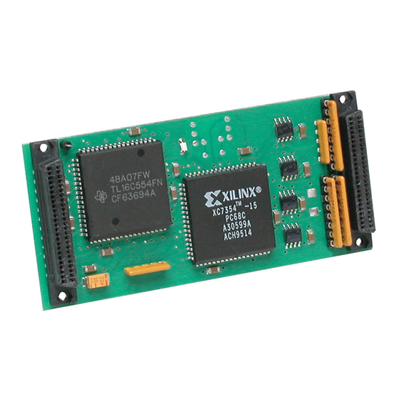
Summary of Contents for Acromag IP502 Series
- Page 1 (217) 352-9330 | Click HERE Find the Acromag IP502 at our website:...
- Page 2 Quad EIA RS-485 Serial Communication Module USER’S MANUAL ACROMAG INCORPORATED 30765 South Wixom Road P.O. BOX 437 Wixom, MI 48393-7037 U.S.A. Tel: (248) 624-1541 Fax: (248) 624-9234 Copyright 1995, Acromag, Inc., Printed in the USA. Data and specifications are subject to change without notice. 8500-547-D02A009...
-
Page 3: Table Of Contents
The information contained in this manual is subject to change IMPORTANT SAFETY CONSIDERATIONS without notice. Acromag, Inc. makes no warranty of any kind with regard to this material, including, but not limited to, the implied It is very important for the user to consider the possible adverse warranties of merchantability and fitness for a particular purpose. -
Page 4: Industrial I/O Pack Interface Features
APC8600 ISA bus (PC/AT) carrier board is also supported. A wide functions are written in the “C” programming language and can be range of other Acromag IP modules are also available to serve your linked to your application. For more details, refer to the signal conditioning and interface needs. -
Page 5: Preparation For Use
For repairs to a product damaged in shipment, refer to the CONNECTORS Acromag Service Policy to obtain return instructions. It is suggested that salvageable shipping cartons and packing material be saved for IP Field I/O Connector (P2) future use in the event the product must be shipped. -
Page 6: Noise And Grounding Considerations
SERIES IP502 INDUSTRIAL I/O PACK QUAD EIA RS-485 SERIAL COMMUNICATION MODULE ___________________________________________________________________________________________ Note that the pin-wire assignments are arranged such that IDC Keep them away from power and other wiring to avoid noise-coupling D-SUB ribbon cable connectors can be conveniently attached to and crosstalk interference. - Page 7 SERIES IP502 INDUSTRIAL I/O PACK QUAD EIA RS-485 SERIAL COMMUNICATION MODULE ___________________________________________________________________________________________ Serial Port A Registers: SERIAL DATA REGISTERS (Per Serial Port): Base Base Addr+ Bit7 Addr+ Receive Buffer Register Transmitter Holding Register READ - IIR Not Driven Port A Interrupt SERIAL STATUS REGISTERS (Per Serial Port): Identification Register Line Status Register...
-
Page 8: Ip Communication & Configuration Registers
SERIES IP502 INDUSTRIAL I/O PACK QUAD EIA RS-485 SERIAL COMMUNICATION MODULE ___________________________________________________________________________________________ Table 3.1D: IP502 I/O Space Memory Map...continued Table 3.1C: IP502 I/O Space Memory Map...continued Serial Port D Registers: Serial Port C Registers: Base Base Base Base Addr+ Bit7 Addr+ Addr+ Bit7... - Page 9 (16MHz). With the 16MHz crystal higher baud rates are disabled by resetting the corresponding IER bit low (0), and enabled possible--you may contact Acromag Applications Engineering to by setting the IER bit high (1). Disabling the interrupt system (IER explore options in this area.
- Page 10 SERIES IP502 INDUSTRIAL I/O PACK QUAD EIA RS-485 SERIAL COMMUNICATION MODULE ___________________________________________________________________________________________ Bits 4 and 5 of this register are always set to 0. Bits 6 and 7 are Interrupt Enable Register set when bit 0 of the FIFO Control Register is set to 1. A power-up IER BIT INTERRUPT ACTION or system reset sets IIR bit 0 to 1, bits 1,2,3,6, and 7 to 0, while bits...
- Page 11 SERIES IP502 INDUSTRIAL I/O PACK QUAD EIA RS-485 SERIAL COMMUNICATION MODULE ___________________________________________________________________________________________ Modem Control Register Modem Status Register FUNCTION PROGRAMMING MSR BIT FUNCTION ∆ CTS - NOT SUPPORTED ∆ 0= DTR* Not Asserted (Inactive) Data DSR - NOT SUPPORTED ∆ 1= DTR* Asserted (Active).
- Page 12 SERIES IP502 INDUSTRIAL I/O PACK QUAD EIA RS-485 SERIAL COMMUNICATION MODULE ___________________________________________________________________________________________ Note that LSR Bits 1-4 (OE, PE, FE, BI) are the error conditions FUNCTION PROGRAMMING that produce a receiver-line-status interrupt (a priority 1 interrupt in Framing 0= No Error the IIR register when any one of these conditions are detected).
-
Page 13: Ip Identification Prom
Address Equivalent (Hex) Field Description Reset All IP's have 'IPAC' Interrupt Read IIR/Write (THRE) THR/Reset Interrupt Read MSR/ (Modem Status Reset Acromag ID Code Changes) IP Model Code RTS* Reset High Not Used DTR* Reset High (Revision) OUT1* Reset High... -
Page 14: Fifo Polled Mode
When the transmit FIFO and transmit interrupts are enabled Acromag provides an Industrial I/O Pack Software Library (FCR Bit 0 = 1 and IER=01), a transmitter interrupt will occur as diskette (Model IPSW-LIB-M03, MSDOS format) to simplify follows: communication with the board. - Page 15 SERIES IP502 INDUSTRIAL I/O PACK QUAD EIA RS-485 SERIAL COMMUNICATION MODULE ___________________________________________________________________________________________ Interrupt Generation Programming Example This model provides individual control for generation of transmit, The following example will demonstrate data transfer between receive, line status, and data set interrupts on each of four channels. one channel of the IP502 and another node.
-
Page 16: Theory Of Operation
EIA/TIA-422B supports full-duplexed single driver multiple receiver a modem control command. Do not confuse the break signal with operation (see Acromag Model IP501). the ASCII Null character, since a break signal is longer than one character time. That is, it is any “space” condition on the line that lasts longer than a single character (including its framing bits) and is usually 1-1/2 to 2 character times long. -
Page 17: Ip502 Operation
It is highly recommended that a non-functioning their corresponding UART pins are tied high (+5V). This includes, board be returned to Acromag for repair. The board can be easily CTS (Clear To Send), RI (Ring Indicator), DSR (Data Set Ready), damaged unless special SMT repair and service tools are used. -
Page 18: Specifications
SERIES IP502 INDUSTRIAL I/O PACK QUAD EIA RS-485 SERIAL COMMUNICATION MODULE ___________________________________________________________________________________________ 6.0 SPECIFICATIONS Data Register Buffers .... The data registers are double- buffered (16C450 mode), or 16-byte FIFO buffered (FIFO mode). GENERAL SPECIFICATIONS Interrupts ....... Receiver Line Status Interrupt (i.e. UART ........Texas Instruments TL16C554FN Overrun error, Parity error, Framing Operating Temperature ..0 to +70°C. -
Page 19: Appendix
Application: Used to connect up to four DB-9 serial ports to AVME9630/9660 non-intelligent carrier board A-D connectors. range 12 to 26 AWG. It is used primarily with Acromag Model IP500, IP501, & IP502 Connections to AVME9630/9660: P1, 50-pin male header with serial communication modules. -
Page 20: Termination Panel: Model 5029-910
(per MIL-G-45204, Type II, Grade C). range 12 to 26 AWG. Connects to Acromag termination panel 5025-552 from the rear Connections to APC8600: P1, 50-pin, high-density male header of the card cage via flat 50-pin ribbon cable (cable Model with strain relief.
Need help?
Do you have a question about the IP502 Series and is the answer not in the manual?
Questions and answers