Table of Contents
Advertisement
Quick Links
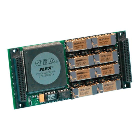
Series IP236A Industrial I/O Pack
FIFO Buffered 16-Bit Analog Output Module
USER'S MANUAL
ACROMAG INCORPORATED
30765 South Wixom Road
P.O. BOX 437
Wixom, MI 48393-7037 U.S.A.
Tel: (248) 295-0310
Fax: (248) 624-9234
Copyright 1999, Acromag, Inc., Printed in the USA.
Data and specifications are subject to change without notice.
8500-889-B11M004
Advertisement
Table of Contents

Related Manuals for Acromag IP236A Series


Summary of Contents for Acromag IP236A Series
- Page 1 FIFO Buffered 16-Bit Analog Output Module USER’S MANUAL ACROMAG INCORPORATED 30765 South Wixom Road P.O. BOX 437 Wixom, MI 48393-7037 U.S.A. Tel: (248) 295-0310 Fax: (248) 624-9234 Copyright 1999, Acromag, Inc., Printed in the USA. Data and specifications are subject to change without notice. 8500-889-B11M004...
-
Page 2: Table Of Contents
5.0 SERVICE AND REPAIR..........The information contained in this manual is subject to change SERVICE AND REPAIR ASSISTANCE......without notice. Acromag, Inc. makes no warranty of any kind with PRELIMINARY SERVICE PROCEDURE...... regard to this material, including, but not limited to, the implied 6.0 SPECIFICATIONS............ -
Page 3: Key Ip236A Features
(see the Acromag Model APC8620 PCIbus carrier User Programmable Interval Timer - Each channel has a board). A wide range of other Acromag IP modules are available user programmable interval timer provided to control the to serve your signal conditioning and interface needs. -
Page 4: Industrial I/O Pack Software Library
I/O Cards, and CompactPCI I/O Cards. The software is temperature. implemented as a library of “C” functions which link with existing user code to make possible simple control of all Acromag PCI The dense packing of the IP modules to the carrier board boards. -
Page 5: Default Hardware Jumper Configuration
SERIES IP236A INDUSTRIAL I/O PACK FIFO BUFFERED 16 BIT ANALOG OUTPUT MODULE ___________________________________________________________________________________________ The board may be configured differently, depending on the Table 2.2: Analog Output Range Selections/Jumper Settings application. Jumper settings are discussed in the following Desired Output Required J1 to J8 J1 to J8 sections. -
Page 6: Analog: Noise And Grounding Considerations
SERIES IP236A INDUSTRIAL I/O PACK FIFO BUFFERED 16 BIT ANALOG OUTPUT MODULE ___________________________________________________________________________________________ Table 2.3: IP236A Field I/O Pin Connections (P2) As an input, the external trigger must be a 5 Volt logic, TTL- Pin Description Number Pin Description Number compatible, debounced signal referenced to analog common. -
Page 7: 3.0 Programming Information
Channel 1 Channel 1 All IP's have Conversion Timer 'IPAC' Channel 1 FIFO Port Channel1 Timer Prescaler Control/Status Acromag ID Code Channel 2 Channel 2 IP Model Code Conversion Timer IP236A- Channel 2 FIFO Port Channel 2 Not Used Timer Prescaler... -
Page 8: Channel Software Reset Register
SERIES IP236A INDUSTRIAL I/O PACK FIFO BUFFERED 16 BIT ANALOG OUTPUT MODULE ___________________________________________________________________________________________ This register can be written with either a 16-bit or 8-bit data value. The channel’s actual conversion will be initiated 6.625 Base Base Adr+ Adr+ seconds after setting its corresponding Start Convert Bit. Timer Prescaler Control/Status Channel 5... -
Page 9: Calibration Coefficient Access Register
Writes to coefficient memory are normally only performed at the factory. The module should be returned to Acromag if recalibration is needed. A write operation to the calibration coefficient memory, initiated via the Calibration Coefficient Access register, will take approximately 5 milliseconds. -
Page 10: Channel Registers
SERIES IP236A INDUSTRIAL I/O PACK FIFO BUFFERED 16 BIT ANALOG OUTPUT MODULE ___________________________________________________________________________________________ CHANNEL REGISTERS FUNCTION 0 = Disable Interrupt Each channel has it own control/status, counters, and FIFO 1 = Enable Interrupt Buffer registers. This allows each channel to function An interrupt request from the IP236A will be independently of all others in the module. -
Page 11: Channel Conversion Timer Register
SERIES IP236A INDUSTRIAL I/O PACK FIFO BUFFERED 16 BIT ANALOG OUTPUT MODULE ___________________________________________________________________________________________ Channel Conversion Timer Register (Read/Write) FIFO). .Upon this interrupt no more then 128 samples minus the threshold value (64, 16, or 4) should be written to the FIFO. Each channel has its own dedicated Timer Prescaler and Conversion Timer pair. -
Page 12: Programming Considerations
This example assumes that the IP236A is installed onto an if the level requested matches that specified by the host. If Acromag AVME9630/60 carrier board (consult your carrier board it matches, the carrier board will assert the INTSEL* line to documentation for compatibility details). -
Page 13: Use Of Calibration Data
Corrected_Count required to accurately produce the output voltage. This is illustrated in the next equation. Software calibration uses some fairly complex equations. Acromag provides you with the Industrial I/O Pack Software Equation (2): Library diskette to make communication with the board and... -
Page 14: 4.0 Theory Of Operation
SERIES IP236A INDUSTRIAL I/O PACK FIFO BUFFERED 16 BIT ANALOG OUTPUT MODULE ___________________________________________________________________________________________ conversions. This will drive channel 0’s analog output to - The Single Conversion mode of operation is used in this example. 2.5 volts. Execute Write of 02H to Channel Control Register at Base (OPTIONAL) Observe or monitor that the specific DAC Address + 09H. -
Page 15: Conversion Control Logic
SERIES IP236A INDUSTRIAL I/O PACK FIFO BUFFERED 16 BIT ANALOG OUTPUT MODULE ___________________________________________________________________________________________ to ID space provides the identification for the individual module external trigger causes a conversion at the DAC. Once the (as given in Table 3.1) per the IP specification. Read and write external trigger signal has been driven low, it should remain low accesses to the I/O space provide a means to control the for a minimum of 250n seconds for proper external trigger... -
Page 16: 5.0 Service And Repair
It is highly recommended that a non-functioning Note: The extended temperature grade version of the DAC714 is board be returned to Acromag for repair. The board can be easily no longer available from the manufacturer. Acromag has damaged unless special SMT repair and service tools are used. -
Page 17: Analog Output
SERIES IP236A INDUSTRIAL I/O PACK FIFO BUFFERED 16 BIT ANALOG OUTPUT MODULE ___________________________________________________________________________________________ ANALOG OUTPUTS Note: 5. The hardware reset function resets the DAC analog output Output Channels……………… IP236A-8 Eight Independent and the FPGA’s internal DAC FIFO buffer. The software reset will only clear the FPGA’s internal DAC FIFO buffer. -
Page 18: Appendix
Connects to panel to the AVME9630/9660 non-intelligent carrier board A- Acromag termination panel 5025-552 from the rear of the D connectors (both have 50-pin connectors). card cage, and to AVME9630/9660 boards within card cage,... -
Page 19: 4501-434 Ip Mechanical Assembly
SERIES IP236A INDUSTRIAL I/O PACK FIFO BUFFERED 16 BIT ANALOG OUTPUT MODULE ___________________________________________________________________________________________ - 19 -... -
Page 20: 4501-736 Ip236A Block Diagram
SERIES IP236A INDUSTRIAL I/O PACK FIFO BUFFERED 16 BIT ANALOG OUTPUT MODULE ___________________________________________________________________________________________ - 20 -... -
Page 21: 4501-737 Analog Output Connection
SERIES IP236A INDUSTRIAL I/O PACK FIFO BUFFERED 16 BIT ANALOG OUTPUT MODULE ___________________________________________________________________________________________ - 21 -... -
Page 22: 4501-735 Jumper Location
SERIES IP236A INDUSTRIAL I/O PACK FIFO BUFFERED 16 BIT ANALOG OUTPUT MODULE ___________________________________________________________________________________________ - 22 -... -
Page 23: 4501-462 Cable 5025-550 (Non-Shielded)
SERIES IP236A INDUSTRIAL I/O PACK FIFO BUFFERED 16 BIT ANALOG OUTPUT MODULE ___________________________________________________________________________________________ - 23 -... -
Page 24: 4501-463 Cable 5025-551 (Shielded)
SERIES IP236A INDUSTRIAL I/O PACK FIFO BUFFERED 16 BIT ANALOG OUTPUT MODULE ___________________________________________________________________________________________ - 24 -... -
Page 25: 4501-464 Termination Panel 5025-552
SERIES IP236A INDUSTRIAL I/O PACK FIFO BUFFERED 16 BIT ANALOG OUTPUT MODULE ___________________________________________________________________________________________ - 25 -... -
Page 26: 4501-465 Transition Module Trans-Gp
SERIES IP236A INDUSTRIAL I/O PACK FIFO BUFFERED 16 BIT ANALOG OUTPUT MODULE ___________________________________________________________________________________________ - 26 -...
Need help?
Do you have a question about the IP236A Series and is the answer not in the manual?
Questions and answers