Table of Contents
Advertisement
Quick Links
Series IP511 Industrial I/O Pack
Isolated Quad EIA-422B Communication Module
USER'S MANUAL
ACROMAG INCORPORATED
30765 South Wixom Road
P.O. BOX 437
Wixom, MI 48393-7037 U.S.A.
Tel: (248) 624-1541
Fax: (248) 624-9234
Copyright 1996, Acromag, Inc., Printed in the USA.
Data and specifications are subject to change without notice.
8500-550-C98M015
Advertisement
Table of Contents

Subscribe to Our Youtube Channel
Related Manuals for Acromag IP511 Series


Summary of Contents for Acromag IP511 Series
- Page 1 Isolated Quad EIA-422B Communication Module USER’S MANUAL ACROMAG INCORPORATED 30765 South Wixom Road P.O. BOX 437 Wixom, MI 48393-7037 U.S.A. Tel: (248) 624-1541 Fax: (248) 624-9234 Copyright 1996, Acromag, Inc., Printed in the USA. Data and specifications are subject to change without notice. 8500-550-C98M015...
-
Page 2: Table Of Contents
The information contained in this manual is subject to change without IMPORTANT SAFETY CONSIDERATIONS notice. Acromag, Inc. makes no warranty of any kind with regard to this material, including, but not limited to, the implied warranties of It is very important for the user to consider the possible adverse merchantability and fitness for a particular purpose. -
Page 3: Signal Interface Products
VMEbus carrier boards). Additionally, ISAbus (PC/AT) carrier boards Acromag provides an Industrial I/O Pack Software Library diskette are supported (see Acromag Model APC8600). A wide range of other (Model IPSW-LIB-M03, MSDOS format) to simplify communication with Acromag IP modules are also available to serve your signal conditioning the board. -
Page 4: Preparation For Use
SIP installed in a socket on the board at the receiver inputs (RxD±). Termination resistors should only be installed at the ends of a For repairs to a product damaged in shipment, refer to the Acromag network and are usually placed at the far-most receiving end, and near Service Policy to obtain return instructions. -
Page 5: Noise And Grounding Considerations
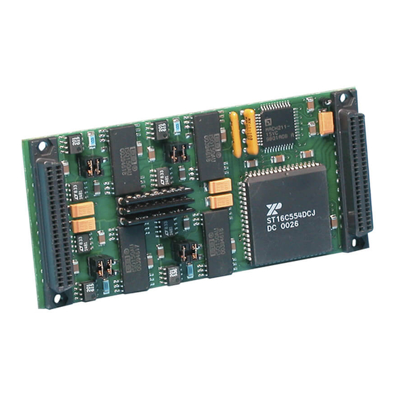
SERIES IP511 INDUSTRIAL I/O PACK ISOLATED QUAD EIA/TIA-422B COMMUNICATION MODULE ___________________________________________________________________________________________ Threaded metric M2 screws and spacers are supplied with the module P2 Pin Signal Descriptions For Model IP511 SIGNAL ± ± ± ± to provide additional stability for harsh environments (see Mechanical DESCRIPTION Assembly Drawing 4501-434). -
Page 6: Ip Logic Interface Connector (P1)
SERIES IP511 INDUSTRIAL I/O PACK ISOLATED QUAD EIA/TIA-422B COMMUNICATION MODULE ___________________________________________________________________________________________ The communication cabling of the P2 interface carries digital data This provides excellent connection integrity and utilizes gold-plating in at a high transfer rate. For best performance, increased signal integrity, the mating area. - Page 7 SERIES IP511 INDUSTRIAL I/O PACK ISOLATED QUAD EIA/TIA-422B COMMUNICATION MODULE ___________________________________________________________________________________________ Note that some functions share the same register address. For Table 3.1: IP511 I/O Space Address (Hex) Memory Map these items, the address lines are used along with the divisor latch Base Base access bit (bit 7 of the Line Control Register) and/or the read and write...
- Page 8 SERIES IP511 INDUSTRIAL I/O PACK ISOLATED QUAD EIA/TIA-422B COMMUNICATION MODULE ___________________________________________________________________________________________ Table 3.1: IP511 I/O Space Address (Hex) Memory Map Table 3.1: IP511 I/O Space Memory Map...continued Base Base Base Base Addr+ Bit7 Addr+ Addr+ Bit7 Addr+ Serial Port C Registers: Serial Port D Registers: READ - RBR READ - RBR...
-
Page 9: Ip Communication & Configuration Registers
With a 16MHz crystal, a 1Mbps baud rate is possible--you may contact invalid data character due to a low-going noise spike on RxD. If the Acromag Applications Engineering to explore options in this area. data on RxD is a symmetrical square wave, the center of the data cells will occur within ±3.125% of the actual center (providing an error margin... - Page 10 SERIES IP511 INDUSTRIAL I/O PACK ISOLATED QUAD EIA/TIA-422B COMMUNICATION MODULE ___________________________________________________________________________________________ Table 3.2: Baud Rate Divisors and Relative Error (8MHz Clk) Enhanced Function Register (EFR) BAUD RATE DIVISOR (N) USED % ERROR DIFF BET EFR BIT FUNCTION DESIRED FOR 16x CLOCK DESIRED &...
- Page 11 SERIES IP511 INDUSTRIAL I/O PACK ISOLATED QUAD EIA/TIA-422B COMMUNICATION MODULE ___________________________________________________________________________________________ Program access to the enhanced functionality provided via bits 4-7 of XON/XOFF-1,2 Registers, Ports A-D (R/W) (Model IP511-64 Only) this register is gained through setting EFR bit 4. For IP511-64 models, programmed values for bits 4-7 cannot be overwritten via existing These registers hold the programmed XON and XOFF characters software if EFR bit 4 is clear (these values are latched when EFR bit 4...
- Page 12 SERIES IP511 INDUSTRIAL I/O PACK ISOLATED QUAD EIA/TIA-422B COMMUNICATION MODULE ___________________________________________________________________________________________ A modem status interrupt (4th priority) will never occur for this LCR - Line Control Register, Ports A-D (Read/Write) model since no handshake lines are provided. Bits 4 and 5 of this register are always set to “0”...
- Page 13 SERIES IP511 INDUSTRIAL I/O PACK ISOLATED QUAD EIA/TIA-422B COMMUNICATION MODULE ___________________________________________________________________________________________ MCR - Modem Control Register, Ports A-D (R/W) Note that on Model IP511-64 units, bits 5-7 are programmable only NO FUNCTION FOR MODEL IP511-16 when the EFR bit 4 is set to “1”. The programmed values for these bits are latched when EFR bit 4 is cleared, preventing existing software from The Modem Control register is normally used to control the inadvertantly overwriting the extended functions.
-
Page 14: Ip Identification Prom
SERIES IP511 INDUSTRIAL I/O PACK ISOLATED QUAD EIA/TIA-422B COMMUNICATION MODULE ___________________________________________________________________________________________ A power-up or system reset sets all LSR bits to 0, except bits 5 and Line Status Register...continued 6 which are high. LSR Bit FUNCTION PROGRAMMING Break 0 = No Break MSR - Modem Status Register, Ports A-D (Read/Write) Interrupt (BI) 1 = Break - the received data input... -
Page 15: The Effect Of Reset
Field Description Reset High Interrupt (RCVR Read LSR/ All IP's have 'IPAC' errors) Reset Interrupt (RCVR Read RCVR data ready) Buffer Register/ Acromag ID Code Reset IP Model Code Interrupt Read Not Used (THRE) IIR/Write THR/Reset (Revision) Interrupt Read MSR/ Reserved... -
Page 16: Fifo Polled Mode
4. A time-out interrupt is cleared and the timer is reset when the CPU reads a character from the receiver FIFO. Acromag provides an Industrial I/O Pack Software Library diskette (Model IPSW-LIB-M03, MSDOS format) to simplify communication with When the transmit FIFO and transmit interrupts are enabled (FCR the board. -
Page 17: Interrupt Generation
SERIES IP511 INDUSTRIAL I/O PACK ISOLATED QUAD EIA/TIA-422B COMMUNICATION MODULE ___________________________________________________________________________________________ In the loopback diagnostic mode, transmitted data is immediately The flow control characters are stored in the XON-1,2 and XOFF- received permitting the host processor to verify the transmit and receive 1,2 registers. -
Page 18: Theory Of Operation
4501-581). However, for true half-duplex EIA-485 operation, please 9. Assuming that data has also been received, read data repeatedly see the Acromag Models IP502 & IP512. from the Receiver Buffer Register. After 14 bytes have been received (or fewer bytes with a timeout), an interrupt will be generated if the host CPU has not already unloaded the receive FIFO. - Page 19 STOP BIT Binary 1 (1, 1-1/2, or 2 Bit times) data paths). Acromag offers both isolated and non-isolated models for EIA/TIA-422B and EIA-485 (consult the factory for information on other With start, stop, and parity in mind, for an asynchronous data byte, serial communication modules).
-
Page 20: Ip511 Operation
It is highly recommended that a non-functioning board be COMMON C isolated power supply common must be returned to Acromag for repair. The board can be easily damaged COMMON D connected here to complete power to the port. If unless special SMT repair and service tools are used. -
Page 21: Specifications
SERIES IP511 INDUSTRIAL I/O PACK ISOLATED QUAD EIA/TIA-422B COMMUNICATION MODULE ___________________________________________________________________________________________ 6.0 SPECIFICATIONS Surge Withstand Capability..Interface lines exhibit no damage when tested with a waveform GENERAL SPECIFICATIONS representative of surges (high UART...........Texas Instruments TL16C554FN frequency transient electrical interference) to ±1KV in isolated or equivalent (Model IP511-16). -
Page 22: Industrial I/O Pack Compliance
Headers (Both Ends): 50-pin female header with strain relief. Header - Acromag Part 1004-512 (3M Type 3425-6600 or equivalent). INDUSTRIAL I/O PACK COMPLIANCE Specification........This module meets or exceeds all Strain Relief - Acromag Part 1004-534 (3M Type 3448-3050 or written Industrial I/O Pack equivalent). specifications per revision 0.7.1. -
Page 23: Termination Panel: Model 5025-552
(per MIL-G-45204, Type II, Grade C). Connects to Printed Circuit Board: Military grade FR-4 epoxy glass circuit board, Acromag termination panel 5025-552 from the rear of the card cage 0.063 inches thick. via flat 50-pin ribbon cable (cable Model Operating Temperature: -40°C to +100°C.
Need help?
Do you have a question about the IP511 Series and is the answer not in the manual?
Questions and answers