Table of Contents
Advertisement
Quick Links
Introduction
W5500S2E-S1 is an industrial grade serial to Ethernet module. It supports TCP server, TCP client and
UDP three operating modes. The maximum serial baud rate is 1.152Mbps. W5500S2E-S1 supports
WIZS2E ConfigTool (Configuration Tool for Windows®), web page configuration and AT command to
configure the module.
W5500S2E-S1 uses the hardwired TCP/IP protocol Ethernet chip W5500. This enable a faster, stable and
secure Ethernet connectivity. With reference schematic(s) and guideline(s) in this user manual, it could
be greatly reduced the time and difficulty of the hardware design and development when comparing with
other approaches.
Features
Specification
W5500S2E-S1 user manual
Arrow.com.
Downloaded from
10/100 Mbps Ethernet interface
Support TCP server, TCP client and UDP operating modes
Flexible serial interface data packaging condition settings
Smart Ethernet cable detection and keep alive features
As DHCP client to automatically acquire IP address
As DNS client to lookup domain name
Support NetBIOS allows user to identify module's name
Support user password authorization for security
Support serial AT command configuration method
Built-in web server for browser and remote configuring
Provide user-friendly configuration tool program (WIZS2E ConfigTool)
Support local and remote firmware upgrade
Serial interface: 3.3V TTL x1: TXD, RXD, GND
Default Serial communication parameters
Baud Rate: From 1.2Kbps to 1.152Mbps
o
Data Bit: 7, 8
o
Stop Bit: 0.5, 1, 1.5, 2
o
Parity: None, Even, Odd
o
Flow Control: None, CTS/RTS
o
Supporting software: Tool: WIZS2E ConfigTool
Configuration methods: WIZS2E ConfigTool, Web based (via web browser), Serial AT command
Power supply: DC 3.3V
Size: 34.0 x 24.0 x 12.4 (mm)
Operating temperature: -40 ~ +85 ℃ (Industrial Grade)
Storage environment: -40 ~ +85 ℃, 5 ~ 95% RH
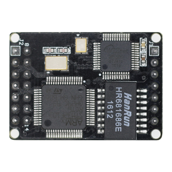
W5500S2E-S1 serial to Ethernet module
Advertisement
Table of Contents

Related Manuals for Wiznet W5500S2E-S1


Summary of Contents for Wiznet W5500S2E-S1
- Page 1 W5500S2E-S1 serial to Ethernet module Introduction W5500S2E-S1 is an industrial grade serial to Ethernet module. It supports TCP server, TCP client and UDP three operating modes. The maximum serial baud rate is 1.152Mbps. W5500S2E-S1 supports WIZS2E ConfigTool (Configuration Tool for Windows®), web page configuration and AT command to configure the module.
- Page 2 Chapter 2.2 RJ45 is modified from 10P to 8P and the corresponding description is modified Add Chapter 5.3 WIZS2E ConfigTool new features introduction Update all WIZS2E ConfigTool screen captures Copyright notice Copyright © WIZnet H.K. Ltd. All rights reserved. Contact E-mail: supports@wiznet.hk For more information, please visit: http://www.wiznet.com.hk/ W5500S2E-S1 user manual Arrow.com.
-
Page 3: Table Of Contents
W5500S2E-S1 serial to Ethernet module Table of Contents INTRODUCTION ......................1 1.1.1 Configuration methods ..................1 ......................1 PECIFICATIONS 1.2.1 Electrical characteristics ..................1 1.2.2 Dimensions ......................2 1.2.3 Thermal Characteristics ..................2 HARDWARE DESCRIPTION ..................3 .................. 3 INOUTS AND PIN DESCRIPTION WIZS2E .................. - Page 4 W5500S2E-S1 serial to Ethernet module 6.4.2 Control commands .................... 22 6.4.3 Device configuration command list ..............24 6.4.4 Serial control command ..................29 ............. 33 COMMAND CONFIGURATION EXAMPLES 6.5.1 Set into TCP server mode example ..............33 6.5.2 TCP client mode example ................. 34 6.5.3...
-
Page 5: Introduction
1 Introduction 1.1.1 Configuration methods W5500S2E-S1 provides three types configuration methods for user to operate with the module. WIZS2E ConfigTool is a computer software configuration tool. It can be installed and run in Windows® environment. Web page configuration allows user locally or remotely to configure the module through web browser. -
Page 6: Dimensions
In the figure, it provides the regulation for three dimensions with the distance of left and right pin headers and the location of the four mounting holes. The pin header has pitch 2.54mm. Figure 1-1 W5500S2E-S1 dimensions top view Figure 1-2 W5500S2E-S1 dimensions side view 1.2.3 Thermal Characteristics... -
Page 7: Hardware Description
3 rows of pin headers on the module as hardware connectors for users. J1 is a 1x7 single row 2.54mm pin and J2 is 2x7 double row 2.54mm pins. Figure 2-2 is the pin assignment of W5500S2E-S1, table 2-1 and 2-2 are the pin header description of W5500S2E-S1 module. - Page 8 W5500S2E-S1 serial to Ethernet module Table 2-1 W5500-S2E J1 pin definition Pin No. Pin Name Features LINK_LED Ethernet Link Indicator ACT_LED Ethernet Status Indicator ALIVE Module operational status indicators TXOP Ethernet connector TXOP pin TXON Ethernet connector TXON pin RXIP...
-
Page 9: Wizs2E Evaluation Board
WIZS2E modules including W5500S2E-S1. Where S1-J1 and S1-J2 are used to plug in the W5500S2E-S1 module, Z1-J1 and Z1-J2 are used to plug in other models of WIZS2E module (s), which are described in the user manuals of the related modules. The evaluation board integrates RJ45, serial TTL and USB mini interfaces. - Page 10 Table 2-5 W5500S2E-S1 evaluation board LED description Hardware connection explanation W5500S2E-S1 used two sections of pin layouts in 1 x 7 pin and 2 x 7 pin designs. This is to avoid plugging the module in the wrong directing which may damage to the module.
-
Page 11: Quick Testing Guide
User Device User Device Figure 2-5 W5500S2E-S1 module testing evaluation block diagram Using LAN cables and USB to Serial (TTL)cables to connect from the host computer and to the respective LAN ports and TTL ports of the evaluation board. This will create a simple testing network;... -
Page 12: Operating Modes
TCP Server Figure 3-1 TCP server mode diagram Figure 3-1 shows, W5500S2E-S1 module open a local port to listen TCP requests in TCP server mode. The default port number is 5000 and it is waiting for client connections. After the connection has created, it will start data communication. -
Page 13: Tcp Client Mode
TCP Client Figure 3-2 TCP client mode diagram According to figure 3-2, W5500S2E-S1 module will starts to connect to TCP server that set in the module for TCP client mode. If connection fails, client will base on reconnection setting condition and try to connect with the TCP server. -
Page 14: Udp Mode
User Device Figure 3-3 UDP mode diagram For UDP mode in Figure 3-3, W5500S2E-S1 module is required to have the remote IP address and port number to create an UDP communication. UDP mode communicate is not based on “connection”. Therefore, it does not guarantee the target device could receive the data correctly or not. -
Page 15: Ip Address
W5500S2E-S1 serial to Ethernet module 4 IP address Before using the module, we need to know some parameters like IP address. This module support “Static” and “DHCP” IP collection method. For “Static” mode, user could manually change the IP address, subnet mask & gateway parameters. The emphasis here is that the IP address of the module cannot be the same as the IP address of other devices in the same LAN. -
Page 16: Module And Host Computer Network Detection
W5500S2E-S1 serial to Ethernet module Figure 4-2 WIZS2E ConfigTool search result 4.3 Module and host computer network detection Before starting to communicate between the WIZS2E module and the host computer, please ensure the host computer and the module are in the same network segment. -
Page 17: How To Config The Ip Address Of The Host Computer
W5500S2E-S1 serial to Ethernet module 4.4 How to config the IP address of the host computer The following procedure is based on Windows® 7 Operation System. Press “Start” → “Control Panel” → “Network Sharing Centre” → “Changing adaptor setting” →... -
Page 18: Wizs2E Configtool
W5500S2E-S1 serial to Ethernet module 5 WIZS2E ConfigTool WIZS2E ConfigTool is a compatibles to W5500S2E and W7500S2E Windows® configuration tool series modules. WIZS2E ConfigTool can be used to search, enquiry and configure W5500S2E and W7500S2E device features and information. 5.1 Collect module’s setting information Click the toolbar’s... -
Page 19: Modify The Device Settings
W5500S2E-S1 serial to Ethernet module Figure 5-2 WIZS2E ConfigTool advance options interface 5.2 Modify the device settings After searching the module, user could directly go to “Basic Settings” and “Advance Options” to configure the module. Please press button to save your configuration. -
Page 20: Factory Reset
W5500S2E-S1 serial to Ethernet module list below the original device list. Figure 5-1 Right mouse click menu 5.4 Factory reset If the customer found out some uncertainties with the WIZS2E module, the user could reset the module back to factory default setting to solve the problem. There are three kinds of method to factory: Software (ConfigTool), AT command and hardware reset. -
Page 21: Hardware Factory Reset Method
5.4.3.2 Factory reset through module Figure 5‑4 through the module default PIN to restore factory settings W5500S2E-S1 has a restored factory set PIN. After power on the module, pull down the DEFAULT pin for 3 seconds to activate factory default. -
Page 22: At Command Configuration
W5500S2E-S1 supports AT command configuration method. This method could only apply when W5500S2E-S1 is in command mode. User needs to send the AT serial command mentioned in this section, W5500S2E-S1 could be modified by requirement. User could use serial terminal or MCU main board that connected with W5500S2E-S1 for applying these configurations. -
Page 23: Enter At Command Mode
This command requires 1 second gap each before and after this command has entered to activate the correct response from W5500S2E-S1. If not, it will consider as user’s data input. This command does not require CRLF (Carriage-Return Line-Feed)(\r\n). The factory default setting of the module is in AT command mode. - Page 24 W5500S2E-S1 serial to Ethernet module 6.3.3 Device configuration command list Features Command Type Max length Parameters / Description AT+SN Device ID Queries only: AT+SN? Queries only: AT+TYPE? Device type AT+TYPE Reply: W5500S2E-S1 Can set into any characters Device name AT+NAME Default: W5500S2E-S1 Must be numbers, alphabets or the mixed of both;...
-
Page 25: Serial Configuration Command List
W5500S2E-S1 serial to Ethernet module 6.3.3 Serial configuration command list Features Command Type Max length Parameters / Description Parameters format: AT+COM1 Serial port 1 parameters [baud],[datab],[parity],[stopb],[c] Default: 7,1,0,1,0 0: 1200; 1: 2400; 2: 4800; 3: 9600; 4: 14400; 5: 19200;... -
Page 26: At Command Details
Parameters / Description Exit from data mode Return value AT-Command Interpreter ready\r\n Under W5500S2E-S1’s data mode, transmitting “+++” through serial interface in the same time will change the module from data mode to command mode. 6.4.2.2 Exit command mode (AT+EXIT) Command format... - Page 27 W5500S2E-S1 serial to Ethernet module 6.4.2.3 Echo (AT+ECHO) Command format Parameters / Description Usage <echo> AT+ECHO=<echo>\r\n Define new value 0: Close Echo feature AT+ECHO?\r\n Query current value 1: Open Echo feature (default) Return value [ECHO] Value is: <echo>\r\nOK\r\n Echo means WIZS2E module could directly return any input values to the serial interface. Thus, this option may help some users working more easily through serial terminal software.
-
Page 28: Device Configuration Command List
W5500S2E-S1 serial to Ethernet module Value ranged is 0 to 4,294,967,295. 6.4.2.9 Ethernet receive counter (AT+NETRCV) Command format Description Usage AT+NETRCV?\r\n Query the byte of data received from Ethernet interface return value [NETRCV] Value is: <number>\r\nOK\r\n Value ranged is 0 to 4,294,967,295. - Page 29 [IP] Value is: <ip>\r\nOK\r\n W5500S2E-S1 support IPv4. IP address format is separate in 4 sections; each section is a decimal value and using a dot to separate. The value range for each section is 0-255 therefore the maximum value size for IP address is 15 bytes.
- Page 30 W5500S2E-S1 serial to Ethernet module 6.4.3.7 Local port binding (AT+C1_BIND) Command format Parameters Usage <bind> AT+C1_BIND=<bind>\r\n Define new value 0: Disable binding local port number AT+C1_BIND?\r\n 1: Enable binding local port number Query current value Return value [C1_BIND] Value is: <bind>\r\nOK\r\n Only available on TCP client mode.
- Page 31 W5500S2E-S1 serial to Ethernet module 6.4.3.12 Remote host IP address (AT+C1_CLI_IP1) Command format Parameters Usage AT+C1_CLI_IP1=<ip>\r\n Define new value <ip> AT+C1_CLI_IP1?\r\n Remote host IP address, default: 192.168.1.99 Query current value Return value [C1_CLI_IP1] Value is: <ip>\r\nOK\r\n Remote host IP address command sets the IP address that communicates with WIZS2E module. This command will only available for TCP client and UDP mode.
- Page 32 [WEB_PORT] Value is: <port>\r\nOK\r\n This port number will be used on W5500S2E-S1’s webserver through web browser. The value range is 0 to 65535. If the port wasn’t set to 80, it needs to add the port number at the end of IP address. For example: 192.168.1.88: 8000.
-
Page 33: Serial Control Command
W5500S2E-S1 serial to Ethernet module 6.4.3.21 Reconnect time (AT+RECONTIME) Command format Parameters Usage AT+RECONTIME=<time>\r\n Define new value <time> AT+RECONTIME?\r\n Reconnect time, default: 0 Query current value Return value [RECONTIME] Value is: <time>\r\nOK\r\n This command configures to limit the time of the TCP client waiting for reconnection the module has disconnected from a TCP server. - Page 34 W5500S2E-S1 serial to Ethernet module 6.4.4.3 Data bit (AT+C1_DATAB) Command format Parameters Usage <datab> AT+C1_DATAB=<datab>\r\n Define new value 0: 7 bit AT+C1_DATAB?\r\n Query current value 1: 8 bit (default) Return value [C1_DATAB] Value is: <datab>\r\n 6.4.4.4 Stop bit (AT+C1_STOPB) Command format...
- Page 35 W5500S2E-S1 serial to Ethernet module This command could handle usage of those remaining data in serial interface after reconnection. 6.4.4.8 Data packaging size (AT+C1_SER_LEN) Command format Parameters Usage AT+C1_SER_LEN=<len>\r\n Define new value <len> The length of the data package, value range: 0 ~ 2048...
- Page 36 W5500S2E-S1 serial to Ethernet module 6.4.4.12 TCP authentication (AT+C1_LINK_P) Command format Parameters Usage <pass> AT+C1_LINK_P=<pass>\r\n Define new value 0: No password is required for TCP connection AT+C1_LINK_P?\r\n Query current value 1: Required password for TCP connection Return value [C1_LINK_P] Value is: <time>\r\n To improve security of communication, the module supports TCP authentication.
-
Page 37: At Command Configuration Examples
W5500S2E-S1 serial to Ethernet module Maximum value: 4,294,967,295 bytes. 6.5 AT command configuration examples 6.5.1 Set into TCP server mode example AT\r\n //Terminal check OK\r\n AT+ECHO=1\r\n //Echo ON [ECHO] Value is: 1\r\n AT+C1_OP=0 \r\n //Operating mode in TCP server [C1_OP] Value is: 0\r\n... -
Page 38: Tcp Client Mode Example
W5500S2E-S1 serial to Ethernet module 6.5.2 TCP client mode example AT\r\n //Terminal check OK\r\n AT+ECHO=1\r\n //ECHO “ON” [ECHO] Value is: 1\r\n AT+C1_OP=1 \r\n //Operating mode in TCP Client mode [C1_OP] Value is: 1\r\n OK\r\n AT+IP_MODE=1\r\n //Set into DHCP mode [IP_MODE] Value is: 1\r\n... -
Page 39: Udp Mode Example
W5500S2E-S1 serial to Ethernet module 6.5.3 UDP mode example AT\r\n //Terminal Check OK\r\n AT+ECHO=1\r\n //Echo ON [ECHO] Value is: 1\r\n AT+C1_OP=2 \r\n //Operating mode in UDP mode [C1_OP] Value is: 2\r\n OK\r\n AT+IP_MODE=1\r\n //Set into DHCP mode [IP_MODE] Value is: 1\r\n... -
Page 40: Web
Before using the web page configuration, you need to make sure that W5500S2E-S1 can be accessed correctly, that is, if you are configuring within the local area network, W5500S2E-S1 needs to be on the same network segment as the computer, and if you are remotely configured, you need to port-map W5500S2E-S1 to the public network IP. - Page 41 Product Information • Device Type: factory default is W5500S2E-S1, cannot be modified. • Device Name: name of module, the factory default is W5500S2E-S1 and it could be changed from the advanced setting page • Firmware Version: shows the firmware version •...
-
Page 42: Basic Settings
Flow Control: Shows the flow control settings, default: NONE * * These settings could be updated in the “Basic Settings” 7.2 Basic Settings Figure 7-4 shows W5500S2E-S1 basic settings page. It is separate into four sections; The following paragraph talking about each section. Figure 7-4 Basic setting page Network Setting •... -
Page 43: Advance Settings
W5500S2E-S1 serial to Ethernet module UART Setting Baud Rate: The baud rate option, default: 115200, between 1.2Kps to 1.152Mpbs Data Bit: The data bit option, default: 8, it could set into 7 or 8 bits Parity: The parity bit option, default: 8, it could set into NONE, ODD or EVEN Stop Bit: The stop bit option, default: 1, it could set into 0.5, 1, 1.5 or 2 bits... - Page 44 If the port wasn’t set to 80, then need to input the port at the end of IP address. For example: 192.168.1.88: 8000. Note: If W5500S2E-S1 works in TCP server mode, HTTP port must not be set to the same as the local port of the module.
-
Page 45: Firmware Information
W5500S2E-S1 serial to Ethernet module 7.4 Firmware Information Clicking “Firmware” tab will let you get into this page that shows on figure 7-8. It contains 2 sections. Firmware Version Firmware: W5500S2E-S1 current firmware version. Firmware Update Please refer section 8-2 for more information on upgrading firmware. - Page 46 W5500S2E-S1 serial to Ethernet module Password setting Old Password: the old password, default: admin New Password: Enter new password, maximum for 16 bytes, it needs to be numbers, alphabets or the combination of both. It does not accept blank as input value.
-
Page 47: Firmware Upgrade
W5500S2E-S1 serial to Ethernet module 8 Firmware Upgrade W5500S2E-S1 supports configuration tools and remote web page firmware upgrade. This two types of upgrades are easy to use; the following information shows the firmware upgrade in both methods. Note: the following firmware MUST be official W5500S2E-S1 firmware from WIZnet H.K. -
Page 48: Firmware Upgrade Through Configuration Web Page
Figure 8-3 firmware upgrade page on web page configuration W5500S2E-S1 will restart the module after the upgrade has completed. The web page will automatically jump back to the login page. W5500S2E-S1 user manual Arrow.com. - Page 49 WIZnet herein. Resale of WIZnet products with provisions different from the information set forth herein shall void any warranty granted by WIZnet for such product. WIZnet and the WIZnet logo are trademarks of WIZnet. All other product or service names are the property of their respective owners.
Need help?
Do you have a question about the W5500S2E-S1 and is the answer not in the manual?
Questions and answers