Table of Contents
Advertisement
Quick Links
Temperature Relays and MINIKA®
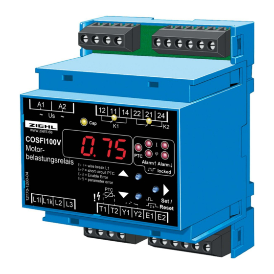
Operating Manual COSFI100V
- Motor load relay, current direction relay
New, Firmware 0-05:
Pr4 optimised for own consumption of energy / preventing from feeding-in of energy
for Display the firmware version press Set for >10s
COSFI100V
12170-0701-04
Mains Monitoring
Digital Panelmeters MINIPAN®
Switching Relays and Controls
Page 1 / 28
ZIEHL industrie – elektronik GmbH + Co KG
Daimlerstr.13, 74523 Schwäbisch Hall, Germany
+ 49 791 504-0,
info@ziehl.de,
Measuring Transducers
Grid- and Plant Protection
updated: 2018-09-07/Fu
from Firmware: 0-05
www.ziehl.de
www.ziehl.de
Advertisement
Table of Contents

Related Manuals for ZIEHL COSFI100V


Summary of Contents for ZIEHL COSFI100V
- Page 1 ZIEHL industrie – elektronik GmbH + Co KG Daimlerstr.13, 74523 Schwäbisch Hall, Germany + 49 791 504-0, info@ziehl.de, www.ziehl.de Temperature Relays and MINIKA® Mains Monitoring Digital Panelmeters MINIPAN® Switching Relays and Controls Measuring Transducers Grid- and Plant Protection updated: 2018-09-07/Fu...
-
Page 2: Table Of Contents
Possible indications in display...................... 24 Factory settings and software version ....................25 10 Maintenance and repair ........................25 11 Troubleshooting and measures ......................26 12 Technical data ............................27 13 Mounting type V4 ..........................28 COSFI100V 12170-0701-04 Page 2 / 28 www.ziehl.de... -
Page 3: Application And Brief Description
In an alternating current motor (inductive load), the current follows phase angle . If the load is decreasing, it increases so that the power factor (cosfi) decreases. This change of phase angle is a gauge of the change of the load on the motor. The COSFI100V motor load monitor is suitable for sinusoidal alternating current signals. -
Page 4: Display And Controls
Displays the alarm messages e.g. 8A18, 8a2L8 Displays the errors with error code e.g. 8Er18, 8Er28, … 8dal8 and( 8dof8, only Pr4), On as 1000 digit for adjust dAl( doF) = Value + 1000s COSFI100V 12170-0701-04 Page 4 / 28 www.ziehl.de... -
Page 5: Detailed Description
Adjustable through menu item 8eN . 8 (8on8 8off8) Enable input (Pr1…3) Contact closed = COSFI100V disabled, no evaluation, good state open = COSFI100V enabled, evaluation after enable time active Floating normally open contact Y1 – Y2 external reset Function same as pressing the Set/Reset key for >2s PTC thermistor connection from motor / generator winding T1 –... -
Page 6: Functional Characteristics
L1l, L1k, L2, L3. Sufficient insulation of the PTC thermistor is mandatory! WARNING Hazardous electrical voltage! Can lead to electric shock and burns. Before starting work, switch plant and device voltage-free. COSFI100V 12170-0701-04 Page 6 / 28 www.ziehl.de... -
Page 7: Mounting
Caution! Before applying mains voltage to the device, make sure that the control voltage U s complies with the mains voltage connected to the device! COSFI100V 12170-0701-04 Page 7 / 28 www.ziehl.de... -
Page 8: Connection Diagram
7 Connection diagram Motor, 3-phase If load current < 10A, connection without a current transformer is possible. 7.2 Motor, 1-phase If load current < 10A, connection without a current transformer is possible. COSFI100V 12170-0701-04 Page 8 / 28 www.ziehl.de... -
Page 9: Current Direction Monitoring (Generator) 3-Phase
7.3 Current direction monitoring (generator) 3-phase If load current < 10A, connection without a current transformer is possible. COSFI100V 12170-0701-04 Page 9 / 28 www.ziehl.de... -
Page 10: Feeding-In, Limiting Or Preventing From, Without Current Transformer
7.4 Feeding-in, limiting or preventing from, without current transformer 7.5 Feeding-in, limiting or preventing from, with current transformer 1) Fuses only when line protection necessary COSFI100V 12170-0701-04 Page 10 / 28 www.ziehl.de... -
Page 11: Explanation Of Limiting Of Or Preventing From Feeding In
Connection according to connection plan. Use Alarm 1 (K1). For second limit use Alarm 2 (K2) and set parameters accordingly. Function: Preventing from feeding in public grid by switching off of 1-phase inverters. When feeding in 3 phases 3 COSFI100V are required. Negative sign: purchase ( - ) Positive sign:... -
Page 12: Increasing Of Own Consumption Without Current Transformer
7.7 Increasing of own consumption without current transformer 7.8 Increasing of own consumption with current transformer 1) Fuses only when line protection necessary COSFI100V 12170-0701-04 Page 12 / 28 www.ziehl.de... - Page 13 Connection according to connection plan. Use Alarm 2 (K2). For second limit use Alarm 1 (K1) and set parameters accordingly. Function: Optimizing of own consumption by switching on additional loads as soon as current in one phase is exceeded. When feeding in 3 phases 3 COSFI100V are required. Negative sign: purchase ( - ) Positive sign:...
-
Page 14: Commissioning
8 Commissioning 8.1 Program setup The appropriate program must be set on the COSFI100V correspondent with the application (cosfi or cosfi plus active current or active current). That is taken care of during commissioning. Measured quantity Limits cos AL1 and AL2... -
Page 15: Pr1 / Al1 And Al2: Cos
Code-Reset = 2 s Set when mains are switched on. (Pin = 504) Error messages: Err1 = Wire break L1 Err2 = PTC short-circuit Err3 = Enable error Err9 = Parameter error COSFI100V 12170-0701-04 Page 15 / 28 www.ziehl.de... -
Page 16: Pr2 / Al1 And Al 2: Active Current (With Current Direction)
= Enable error Err9 = Parameter error * at current factor 8f > 1 the displayed values are multiplied by the factor. Resolution 0,1 A x factor e.g. 2,0 A at current transformer 100/5 A. COSFI100V 12170-0701-04 Page 16 / 28 www.ziehl.de... -
Page 17: Pr3 / Al1: Cos And Al 2: Active Current (With Current Direction)
= Enable error Err9 = Parameter error * at current factor 8f > 1 the displayed values are multiplied by the factor. Resolution 0,1 A x factor e.g. 2,0 A at current transformer 100/5 A. COSFI100V 12170-0701-04 Page 17 / 28 www.ziehl.de... -
Page 18: Pr4 / Al1 Und Al 2: Active Current (With Current Direction)
= Enable error Err9 = Parameter error * at current factor 8f > 1 the displayed values are multiplied by the factor. Resolution 0,1 A x factor e.g. 2,0 A at current transformer 100/5 A. COSFI100V 12170-0701-04 Page 18 / 28 www.ziehl.de... -
Page 19: Description Of The Parameters
Interval during which the display in the display … 8ddi8 880. 1 882.08 Delay display mode is updated PTC thermistor 8off8, 8AL18, 8PtC8 Configure PTC depending on the application 8AL28 Input COSFI100V 12170-0701-04 Page 19 / 28 www.ziehl.de... -
Page 20: Display Mode
8.7 Display mode (last decimal point off) In the display mode, the COSFI100V is in the normal state; the current cos and/or active current is ,…) and displayed here depending on the program. In addition, the alarm messages (e.g. 8A188, 8a2L8 , …) are also displayed. -
Page 21: Alarm Configuration
• Set the desired parameter using the Up and Down keys • Press the Set key Display 8AL1. • Press Down key Display 8AL2. • Repeat configuration for Alarm 2 only in programs 2 and 3 (see also 8.2…8.5 control diagram) COSFI100V 12170-0701-04 Page 21 / 28 www.ziehl.de... -
Page 22: Enable, Delay-Display And Ptc Configuration
(PTC / Current Parameter) flash alternately • Set the desired parameter using the Up and Down keys • Press the Set key Display 8PtC. (Delay Alarm) not in all programs adjustable COSFI100V 12170-0701-04 Page 22 / 28 www.ziehl.de... -
Page 23: Simulation
8 on8 flashes three times Code lock EasyLimit, Display 8 EL8 flashes three times Code lock off, display 8off8 flashes three times Return to menu mode, menu item code lock COSFI100V 12170-0701-04 Page 23 / 28 www.ziehl.de... -
Page 24: Possible Indications In Display
Delay starts, waiting time between reconnection attempts 8ddi8 Delay display, to quiet down the display 8PtC8 PTC thermistor Simulation 8Cod8 Code lock 8Pin8 Pin code (factory setting 504) 8 el8 Easy Limit (only limits can be set) COSFI100V 12170-0701-04 Page 24 / 28 www.ziehl.de... -
Page 25: Factory Settings And Software Version
Display the program: Press the "Set" key for 4 s in the display mode. Display the software version: Press the "Set" key for 10 s in the display mode. 10 Maintenance and repair The COSFI100V is maintenance-free. Periodically test for proper functioning. COSFI100V 12170-0701-04 Page 25 / 28 www.ziehl.de... -
Page 26: Troubleshooting And Measures
L1l and L1k mixed up (Direction of current is connection diagram! false) Pay attention to the sign LED! Device does not switch For underload monitor cos , Change of measured value too low for overload monitor current COSFI100V 12170-0701-04 Page 26 / 28 www.ziehl.de... -
Page 27: Technical Data
Rated insulation voltage Ui 250 V Operating time 100 % Permissible ambient temperature -20 °C... +55 °C EN 60068-2-2 dry heat EMC - noise immunity EN 61000-6-2 EMC - noise emission EN 61000-6-3 COSFI100V 12170-0701-04 Page 27 / 28 www.ziehl.de... -
Page 28: Mounting Type V4
Bar for wall mounting with screws. Bar drill hole Ø 4.2 mm / for fixing to wall with screws, Ø 4.2 Sie finden diese und weitere Betriebsanleitungen, soweit verfügbar auch in englisch, auf unserer Homepage www.ziehl.de. You find this and other operating-manuals on our homepage www.ziehl.de, as far as available also in English. COSFI100V 12170-0701-04 Page 28 / 28 www.ziehl.de...
Need help?
Do you have a question about the COSFI100V and is the answer not in the manual?
Questions and answers