ZIEHL UFR1001E Operating Instructions Manual
Voltage and frequency
Hide thumbs
Also See for UFR1001E:
- Operating manual (46 pages) ,
- Short operating manual (9 pages) ,
- Quick manual (8 pages)
Table of Contents
Advertisement
Quick Links
Temperature Relays and MINIKA®, Mains Monitoring, Digital Panelmeters MINIPAN®, Switching Relays and Controls
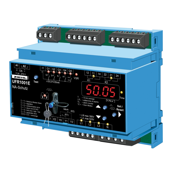
Operating Instructions UFR1001E
- NA-protection according to VDE-AR-N 4105, in-plant power generators on the low voltage grid
- For use in in-plant power generators on the medium voltage grid according to BDEW
- With selectable vector shift detection
- With selectable Rate of Change of Frequency (ROCOF, df/dt) protection
New, Firmware 0-04:
ROCOF (df/dt) protection
Display of the firmware version:
UFR1001E
12420-0701-03
or press "Set" for >10s
8fnr
8Info8
8
Page 1 / 36
ZIEHL industrie – elektronik GmbH + Co KG
Daimlerstraße 13, D – 74523 Schwäbisch Hall
+ 49 791 504-0, info@ziehl.de, www.ziehl.de
updated: 131014 Fz/Ba
from Firmware: 0-04
www.ziehl.de
Advertisement
Table of Contents

Subscribe to Our Youtube Channel
Related Manuals for ZIEHL UFR1001E


Summary of Contents for ZIEHL UFR1001E
- Page 1 ZIEHL industrie – elektronik GmbH + Co KG Daimlerstraße 13, D – 74523 Schwäbisch Hall Temperature Relays and MINIKA®, Mains Monitoring, Digital Panelmeters MINIPAN®, Switching Relays and Controls + 49 791 504-0, info@ziehl.de, www.ziehl.de updated: 131014 Fz/Ba Operating Instructions UFR1001E...
-
Page 2: Table Of Contents
16. Guidance value changes according to ÖVE/ÖNORM E 8001-4-712 ..........35 17. Adjustment values table VDE-AR-N 4105, Low Voltage Pr 1+2 ............36 18. Adjustment values table BDEW June 2008, acc 3.2.3.3-1, Medium Voltage Pr 3-6 ......36 UFR1001E 12420-0701-03 Page 2 / 36... -
Page 3: Application And Brief Description
1. Application and brief description The UFR1001E system-disconnection relay monitors voltage and frequency in three-phase current networks. In complies with the conditions for centralized NA-protection according to VDE-AR-N 4105 in in- plant power generators >30kVA, for feeding into the low voltage grid and the BDEW Directive for feeding into the medium voltage grid. -
Page 4: Display And Controls
Voltage value (L1 against N, L2 against N, L3 against N) Lx and Ly ON Voltage value (L1 against L2, L2 against L3, L1 against L3) Lx FLASHING quickly Vector surge (L1, L2, L3) L1 FLASHING Frequency UFR1001E 12420-0701-03 Page 4 / 36 www.ziehl.de... -
Page 5: Detailed Description
After a tripping time with the test button it is displayed until a button is (only with feedback pressed again with a resolution of up to 1ms. contacts connected) dal. Total shut-down time = Tripping time + Response time UFR1001E 12420-0701-03 Page 5 / 36 www.ziehl.de... -
Page 6: Important Information
WARNING Hazards electrical voltage! Can lead to an electric shock and burns. Disconnect and de-energize before working on the system and the device. UFR1001E 12420-0701-03 Page 6 / 36 www.ziehl.de... -
Page 7: Assembly
Caution! Before you apply mains voltage to the device, make sure that the permissible control voltage Us on the side rating plate matches the mains voltage connected to the device! UFR1001E 12420-0701-03 Page 7 / 36 www.ziehl.de... -
Page 8: Connection Diagrams
Contact closed suppresses evaluation of feedback contacts and vector shift on.8 (8vsr ) suppresses feedback contacts (8vsr 8y1y2.8 ) or switches device into standby (8vsr 8stby.8 = default setting) e.g. through ripple control receiver or timer UFR1001E 12420-0701-03 Page 8 / 36 www.ziehl.de... -
Page 9: Multiple Pv With Section Switch And With A Series-Switched Nc's As Feedback Contacts (Expanded Inventory Plant)
Contact closed suppresses evaluation of feedback contacts and vector shift on.8 (8vsr ) suppresses feedback contacts (8vsr 8y1y2.8 ) or switches device into standby (8vsr 8stby.8 = default setting) e.g. through ripple control receiver or timer UFR1001E 12420-0701-03 Page 9 / 36 www.ziehl.de... -
Page 10: Multiple Pv With Section Switch And With A Parallel-Switched Closing Contacts As Feedback Contacts (Expanded Inventory Plant)
Contact closed suppresses evaluation of feedback contacts and vector shift on.8 (8vsr ) suppresses feedback contacts (8vsr 8y1y2.8 ) or switches device into standby (8vsr 8stby.8 = default setting) e.g. through ripple control receiver or timer UFR1001E 12420-0701-03 Page 10 / 36 www.ziehl.de... -
Page 11: Pv, 1X Section Switch With Nc/Normally Closed Contacts (Medium Voltage)
Contact closed suppresses evaluation of feedback contacts and vector shift on.8 (8vsr ) suppresses feedback contacts (8vsr 8y1y2.8 ) or switches device into standby (8vsr 8stby.8 = default setting) e.g. through ripple control receiver or timer UFR1001E 12420-0701-03 Page 11 / 36 www.ziehl.de... -
Page 12: Generator Operation, Suppression Of The Feedback Contacts (With External Shut-Down And Mains Synchronization)
Contact closed suppresses evaluation of feedback contacts and vector shift on.8 (8vsr ) suppresses feedback contacts (8vsr 8y1y2.8 ) or switches device into standby (8vsr 8stby.8 = default setting) e.g. through ripple control receiver or timer UFR1001E 12420-0701-03 Page 12 / 36 www.ziehl.de... -
Page 13: Commissioning
8. Commissioning Program setup The suitable program must be set on the UFR1001E in accordance with the application. If the UFR1001E is sealed/locked (red LED illuminated), the sealing has to be deactivated first. Connection Threshold values Voltage Low voltage 3 AC with N... -
Page 14: Control Chart
(Pin = 504) Error messages: Err4 = Tolerance Master Slave Err5 = Internal control Err6 = Communication Err7 = Contactor feedback contacts K1/K2 Err8 = Limit error Err9 = Parameter error UFR1001E 12420-0701-03 Page 14 / 36 www.ziehl.de... - Page 15 (Pin = 504) Error messages: Err4 = Tolerance Master Slave Err5 = Internal control Err6 = Communication Err7 = Contactor feedback contacts K1/K2 Err8 = Limit error Err9 = Parameter error UFR1001E 12420-0701-03 Page 15 / 36 www.ziehl.de...
-
Page 16: Description Of The Parameters
Display mode (last decimal point off) In the display mode, the UFR1001E is in its normal state; here, depending on the program, the actual voltage, the highest actual 10 minute mean value, the frequency or the vector surge is displayed. In addition, the alarm signals (e.g. -
Page 17: Menu Mode (Last Decimal Point On)
The alarm counter 8ac is increased by 1 with every shut-down. Up to 100 shut-downs are counted. That allows quick detection of how often the UFR1001E has shut down since the last delete of the alarm counter (see cumulative alarm time). -
Page 18: Alarm Memory
8.11 Standby counter and standby time The standby counter 8stby8, is increased by 1 with every standby shut-down. Up to 9999 shut-downs are counted. That lets the UFR1001E quickly detect how often, e.g., shut-down was performed through a ripple control receiver. -
Page 19: Code Lock
All the settings and the simulation mode can be locked. If the LED is illuminated, the UFR1001E is locked. If an attempt is made to change a setting in the locked state, for 3s the display shows 8LOc 8. Adjustment procedure Sealing/Lock ON (OFF): ... -
Page 20: Simulation
If the UFR1001E is sealed/locked, simulation is not possible. If the section switch feedback contacts are connected to the UFR1001E and enabled, (set value > section- switch turn-on time under 8trel.8), after a shut-down, the tripping time (dAL + time of slowest section switch) is displayed. -
Page 21: Possible Indications In Display
Info8 Device information, program change , 8snr Firmware version, serial number Operating hours , 8del Error counter, delete error counter 8yes , 8no Yes, no query for acknowledgement Program 8 oFF8 On, Off UFR1001E 12420-0701-03 Page 21 / 36 www.ziehl.de... -
Page 22: Default Settings And Firmware Version
51. 5 0 51. 5 0 51. 5 0 51. 5 0 51. 5 0 F, Overfrequency 1.45 1.45 1.45 1.45 1.45 1.45 Hysteresis 0.10 0.10 0.10 0.10 0.10 0.10 Response time OFF-delay UFR1001E 12420-0701-03 Page 22 / 36 www.ziehl.de... - Page 23 Operating hours xxxxx xxxxx xxxxx xxxxx xxxxx xxxxx Error counter Program * default setting 8Pr Display of the program: 8Info8 or when switching on 8fnr Display of the firmware version: 8Info8 UFR1001E 12420-0701-03 Page 23 / 36 www.ziehl.de...
-
Page 24: Technical Data
0 (>200ms) … 999 s Reset time Measurement time Number of adjusted Periods * Periods duration + Response time Digital outputs (galvanic isolated) DC 4.5…27 V Switching voltage I1 Current Q1…Q5 Max 20 mA / output UFR1001E 12420-0701-03 Page 24 / 36 www.ziehl.de... -
Page 25: Maintenance And Repair
(additional bar not included in the scope of delivery) Weight: approx. 250 g We reserve the right to make technical changes 11. Maintenance and repair The UFR1001E is maintenance-free. Periodically test for proper functioning. UFR1001E 12420-0701-03 Page 25 / 36 www.ziehl.de... -
Page 26: Troubleshooting And Measures
8stby8 appears in the Standby mode, E1-E2 closed vsr. Check parameter display and LED Q3 hysteresis for 8F, Ceck hysteresis for reset point (f>) is on, reading in incorrectly 50,05 Hz good range UFR1001E 12420-0701-03 Page 26 / 36 www.ziehl.de... -
Page 27: Construction Form V6
Sealing max. Ø 1.8 mm Frontplatteneinsatz / front panel Kennzeichen für unten / position downward Bar for wall attachment with screws. Riegelbohrung Ø 4,2 mm / Bolt hole for fixing to wall with screws, Ø 4.2 mm. UFR1001E 12420-0701-03 Page 27 / 36 www.ziehl.de... -
Page 28: Verification Of Conformity
14. Verification of conformity UFR1001E 12420-0701-03 Page 28 / 36 www.ziehl.de... - Page 29 UFR1001E 12420-0701-03 Page 29 / 36 www.ziehl.de...
- Page 30 UFR1001E 12420-0701-03 Page 30 / 36 www.ziehl.de...
- Page 31 UFR1001E 12420-0701-03 Page 31 / 36 www.ziehl.de...
- Page 32 UFR1001E 12420-0701-03 Page 32 / 36 www.ziehl.de...
- Page 33 UFR1001E 12420-0701-03 Page 33 / 36 www.ziehl.de...
-
Page 34: Unbedenklichkeitsbescheinigung Öve/Önorm E 8001-4-712
15. Unbedenklichkeitsbescheinigung ÖVE/ÖNORM E 8001-4-712 UFR1001E 12420-0701-03 Page 34 / 36 www.ziehl.de... -
Page 35: Guidance Value Changes According To Öve/Önorm E 8001-4-712
Repeat for all enabled limits Hint: When changing programs, all parameters of the selected program are reset to “default settings“ (see table „Default settings“). Change the parameters after having selected the correct program. UFR1001E 12420-0701-03 Page 35 / 36... -
Page 36: Adjustment Values Table Vde-Ar-N 4105, Low Voltage Pr 1+2
0.45 U 300 ms 50.0 – 65.0 Hz Frequency increase protection f> 51.5Hz 100 ms 45.0 – 50.0 Hz Frequency decrease protection f< 47.5Hz 100 ms * Not enabled in as delivered condition UFR1001E 12420-0701-03 Page 36 / 36 www.ziehl.de...
Need help?
Do you have a question about the UFR1001E and is the answer not in the manual?
Questions and answers