Table of Contents
Advertisement
Quick Links
Advertisement
Table of Contents

Related Manuals for Aim-TTI QPX750SP


Summary of Contents for Aim-TTI QPX750SP
- Page 1 INSTRUCTION MANUAL INSTRUCTION MANUAL QPX750SP 750W Laboratory Power Supply...
-
Page 2: Table Of Contents
CONTENTS Product Description ........................2 Safety ............................... 3 Symbols ..............................3 Safety notices ............................4 Installation ............................5 Mounting ..............................5 Ventilation ............................... 5 Electrical Requirements .......................... 5 Instrument Overview ........................6 Front Panel ............................. 6 Rear Panel .............................. 8 Getting Started ..........................10 Using this manual .......................... -
Page 3: Product Description
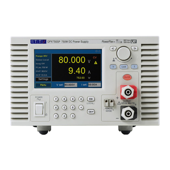
1 - Product Description 1 PRODUCT DESCRIPTION The QPX750 is a single output laboratory power supply with a maximum output power of 750 watts. The PoweFlex+ design provides voltages up to 80V, currents up to 50A and flexible modes of operation (CC, CV, and CP) with automatic crossover, while offering an exceedingly wide range of operation, as detailed in the PowerFlex + curve. -
Page 4: Safety
2 - Safety 2 SAFETY 2.1 Symbols This instruction manual contains information and warnings which must be followed by the user to ensure safe operation and to retain the instrument in a safe condition. The following symbols are displayed on the instrument and throughout the manual, to ensure the safety of the user and the instrument, all information must be read before proceeding. -
Page 5: Safety Notices
2 - Safety 2.2 Safety notices This instrument is: · A safety Class I instrument according to IEC classification and has been designed to meet the requirements of EN61010-1 (Safety Requirements for Electrical Equipment for Measurement, Control and Laboratory Use). It is an Installation Category II instrument intended for operation from a normal single-phase supply. -
Page 6: Installation
3 - Installation 3 INSTALLATION 3.1 Mounting For rack mounting, the feet should be removed such that the instrument can be fitted beside any other standard 3U half-rack instrument in a 19” rack. A suitable 3U 19” rack kit is available from the manufacturer or their overseas agents - a RM460 19-inch rack kit accommodates two instruments. -
Page 7: Instrument Overview
4 - Instrument Overview 4 INSTRUMENT OVERVIEW 4.1 Front Panel 4.1.1 Overview 4.1.2 ① Colour Touch Screen Display CAUTION Do not use sharp objects or pointed objects to operate the touch screen. ② Power Switch Power Switch is located in the bottom left-hand corner. Press to start the unit. CAUTION When instrument is in Standby mode, Mains is still present. - Page 8 4 - Instrument Overview CAUTION Voltage drop on sense leads should not exceed 2V. NOTE To avoid instability and transient response problems, care must be taken to ensure good coupling between each output and sense lead; this can best be done by twisting the leads together.
-
Page 9: Rear Panel
4 - Instrument Overview 4.2 Rear Panel ① AC power inlet ② GPIB (optional) Requires GPIB 1A user retrofittable option. The default GPIB address is 11. ③ LAN The LAN interface is designed to meet 1.5 LXI (LAN extensions for Instrumentation) Core 2016. Remote control using the LAN interface is possible using a TCP/IP Socket protocol. - Page 10 4 - Instrument Overview V CONTROL and I CONTROL are 0…5V or 0…10V inputs with respect to COM terminal that provide quasi-analogue control of the Output Voltage and Current Control, respectively. The output terminal voltage and output current may be monitored on V MONITOR and I MONITOR, respectively.
-
Page 11: Getting Started
5 - Getting Started 5 GETTING STARTED 5.1 Using this manual This section is a general introduction to the operation of the instrument and is intended to be read before using the Power Supply for the first time. In this manual front panel keys and sockets are shown in capitals, e.g. ON, OFF. Text, entry fields and messages displayed on the LCD are shown in a different font, e.g. -
Page 12: Home Screen / Settings Menu
5 - Getting Started 5.3 Home Screen / Settings Menu The Home Screen will be shown when the instrument is powered on. It will include the default parameters. To set volts or amps, select the parameter window and enter the value required. See ‘Navigation controls' for more details. -
Page 13: Meter Status
5 - Getting Started 5.4 Meter status The following symbols may appear in the meter display: Mode ith the output on, the mode shown will be: CV (Constant Voltage), CC (Constant Current) or CP (Constant Power), depending on the set limits and load conditions. The display will show the actual output voltage and current at the terminals. - Page 14 5 - Getting Started 5.4.1 Meter colours If the output is switched off, the meter volts and current will be displayed in Grey. If the output is turned on the active volts will be shown in Yellow. If the output is turned off but there are still volts present from an external source, that voltage measurement is shown in Red.
-
Page 15: Status Bar
5 - Getting Started 5.5 Status bar ① Analog Control When choosing an active option on ‘Analog Control’, the choice of: V Only, I Only, V&I will appear in the status bar. ② Sense Trip If SNS Trip appears, a sense error has occurred and caused a trip. The output is tripped off if the voltage between an output terminal and its corresponding sense terminal exceeds approximately 2V;... -
Page 16: Navigation Controls
5 - Getting Started 5.6 Navigation controls The versatile user interface can be navigated using the touch screen, rotary knob, front panel keys or a combination of all three options. Many settings can be made quickly and easily using the touch screen alone; the rotary knob is most useful when, for example, a parameter is being frequently increased or decreased during manual testing. -
Page 17: Menu
6 - Menu 6 MENU This gives access to the menus used to: · Set up operational parameters for the instrument, system, and remote interface. · View messages, instrument information, and Help menus. · Save and recall instrument setup. · Calibrate the instrument. - Page 18 6 - Menu 6.1.2 Analog Control Menu>Instrument>Analog Control Analog signal connections V CONTROL and I CONTROL are available from the terminal block on the ‘Rear Panel’. These can provide quasi-analog control of Output Voltage and Current Limit, respectively. Control Type: None: deselects the analog input, output voltage is ·...
- Page 19 6 - Menu 6.1.3 Logic Control Menu>Instrument>Logic Control Digital signal connections LOGIC IN and LOGIC OUT are available from the terminal block on the ‘Rear Panel’. Logic Out LOGIC OUT is an isolated rear-panel, open-collector output that will sink up to 2mA when active (‘switch closure’);...
- Page 20 6 - Menu 6.1.4 Save Menu>Instrument>Save Instrument setups can be saved as a file to the internal storage, these settings include: · Set volts, current and power limit · Selected Range · Over voltage and Over current protection · Sense terminal setup ·...
-
Page 21: System
6 - Menu 6.2 System Menu>System This menu controls the look and feel of the instrument, it allows the user to set the operational parameters that affect the system use. Brightness Increase/decrease screen brightness by using the rotary knob to scroll through the options, or the touch screen to manually enter a value. -
Page 22: Interface
6 - Menu 6.3 Interface Menu>Interface This menu allows the user to set the operational parameters that affect remote interface use. 6.3.1 LAN Reset Menu>Interface>LAN Reset Resets LAN configuration to default setting, removing any changes made in ‘LAN Settings’. 6.3.2 LAN Settings Menu>Interface>LAN Settings IP Configuration Method: ·... -
Page 23: Messages
6 - Menu 6.4 Messages Menu>Messages · Last Displayed Message: A pop-up will appear with the last opened message. By pressing OK, the user will be returned to the messages screen. · Remote Error Message Queue: Displays any error message that occurred while using Remote Command. -
Page 24: Info
6 - Menu 6.5 Info Menu>Info This will show information on the instrument that cannot be changed, including: · Manufacturer · Firmware · Serial number · MAC address · Socket Port 6.6 Help Menu>Help A list of all operations listed in this manual will be displayed. -
Page 25: Defaults
6 - Menu 6.8 Defaults Menu> Defaults Some, or all, of the instruments original factory default settings can be restored in this menu. When activated, a pop- up with the following choices will be shown: · Instrument: Will reset the settings that have been changed in Menu>Instrument, in addition to the PSU parameters, to default. -
Page 26: Messages
7 - Messages. 7 MESSAGES. 7.1 Error Messages Error messages are shown on the display until the ESC key is pressed. This will immediately remove the pop-up box and execute the function of the key which is pressed. REM LOCK will appear when they keypad is locked while in remote mode. -
Page 27: Maintenance
8 - Maintenance 8 MAINTENANCE The manufacturers or their agents overseas will provide a repair service for any unit developing a fault. Where owners wish to undertake their own maintenance work, this should only be done by skilled personnel in conjunction with the Service Manual which may be obtained directly from the manufacturer or their agents overseas. -
Page 28: Firmware Update
8 - Maintenance 8.2 Firmware update 1. Instrument firmware can be updated via a USB or LAN connection. Connect the instrument before starting the process. 2. The latest Firmware update, together with file transfer utility can be downloaded from https://www.aimtti.com/ 3. -
Page 29: Remote Operation
9 - Remote Operation 9 REMOTE OPERATION The instrument can be remotely controlled via its USB, LAN or (optional) GPIB interfaces. 9.1 USB Interface Using the USB interface for remote control requires a Communications Device Class driver on the PC to provide a virtual COM port instance. -
Page 30: Lan Interface
9 - Remote Operation 9.2 LAN Interface The LAN interface is designed to meet 1.5 LXI Device Specification 2016. Remote control using the LAN Interface is possible using the TCP/IP Sockets protocol. The instrument also contains a basic web server which provides information on the instrument and allows it to be configured from a web browser. - Page 31 9 - Remote Operation 9.2.2 Web server; configuration password protection The unit contains a basic web server. This provides information on the instrument and allows it to be configured. The Settings page can be password protected to deter unauthorised changes to the remote operation configuration.
-
Page 32: Gpib Interface
9 - Remote Operation 9.3 GPIB Interface The GPIB interface 24-way connector is located on the instrument rear panel (requires GPIB option 1A fitted). The pin connections are as specified in IEEE Std. 488.1-1987 and the instruments in the range complies with IEEE Std. -
Page 33: Status Reporting
9 - Remote Operation 9.3.3 GPIB Parallel Poll Complete parallel poll capabilities are offered on this instrument. The Parallel Poll Enable Register is set to specify which bits in the Status Byte Register are to be used to form the ist local message. The Parallel Poll Enable Register is set by the *PRE<NRF>... - Page 34 9 - Remote Operation 9.4.1 Standard Event Status and Standard Event Status Enable Registers These two registers are implemented as required by the IEEE Std. 488.2. Any bits set in the Standard Event Status Register which correspond to bits set in the Standard Event Status Enable Register will cause the ESB bit to be set in the Status Byte Register.
- Page 35 9 - Remote Operation 9.4.2 Execution Error Register This register contains a number representing the last error encountered over the current interface. The Execution Error Register is read and cleared using the ‘EER?’ command. On power up this register is set to 0 for all interface instances. Error messages have the following meaning: No error encountered Indicates a hardware error has been encountered...
- Page 36 9 - Remote Operation 9.4.4 Status Byte Register and Service Request Enable Register These two registers are implemented as required by the IEEE Std. 488.2. Any bits set in the Status Byte Register which correspond to bits set in the Service Request Enable Register will cause the RQS/MSS bit to be set in the Status Byte Register, thus generating a Service Request on the bus.
-
Page 37: Remote/ Local Operation
9 - Remote Operation 9.4.5 Status Model 9.5 Remote/ local operation At power-on, the instrument will be in the local state and the REM indicator is not displayed on the Status Line. In this state, all front panel operations are possible. When the instrument receives a command from an interface the remote state will be entered, and the REM indicator will be displayed on the Status Line. -
Page 38: Parameter Data Format
9 - Remote Operation 9.6 Parameter Data Format <NR1> Digits with no fractional part, i.e., an integer Example: 451 <NR2> Digits with an explicit decimal point. Example: 0.451 <NR3> Digits with an explicit decimal point and an exponent. Example: 45.1e+01 <NRF>... -
Page 39: Scpi Commands
9 - Remote Operation 9.8 SCPI Commands 9.8.1 SCPI Overview This instrument uses SCPI (Standard Commands for Programmable Instruments) commands for remote control. The commands are based on SCPI Version 1999 and follow the syntax and rules including commands that are not taken from the SCPI standard. These commands are separated into two groups: common and subsystem. -
Page 40: Scpi Subsystems
9 - Remote Operation 9.9 SCPI Subsystems :SOURce The SOURce subsystem contains the commands for configuring the output signal. :OUTPut The OUTPut subsystem configures the output signal state. :MMEMory The MMEMory subsystem is used to manage instrument setups. :STATus The STATus subsystem is used to query the Operation Condition Register :SYSTem The SYSTem subsystem is used for a number of functions not associated with the output signal, such as configuring the LAN. - Page 41 9 - Remote Operation · :SYSTem:COMMunicate:LAN:PRIDNS:DESired <Quad> Set the IP address of the primary DNS server on the network when MANual configuration is used · :SYSTem:COMMunicate:LAN:SECDNS:DESired <Quad> Set the IP address of the secondary DNS server on the network · :SYSTem:COMMunicate:LAN:IPADdress[:RESolved]? Query the resolved IP address in use on the network.
- Page 42 9 - Remote Operation 9.9.2 STATus Subsystem · :STATus:OPERation:CONDition? Query the Status Operation Condition register. See Status reporting section for details. The content is not deleted after being read as it indicates the current operating status · :STATus:OPERation:ENABle <NRF> Set Status Operation Enable Register to <NRF>...
- Page 43 9 - Remote Operation · [SOURce:]CURRent:PROTection:CLEar Attempt to clear the OCP trip. · [SOURce:]VOLTage:PROTection[:LEVel] <NRF> Set the Over Voltage Protection trip point to <NRF> NV|UV|MV|V|KV|MAV · [SOURce:]VOLTage:PROTection:TRIPped? Query the Over Voltage Protection status of the unit. Response is of the format 0 if the OVP tripped has not occurred and 1 if OVP tripped has occurred.
-
Page 44: Factory Default Settings
10 - Factory default settings 10 FACTORY DEFAULT SETTINGS Output Configuration Factory Setting Settings Voltage Amps 1.00A Range Sense Local Iavg Plim 750W Power on State Output State Always Off Power on State Latest Params Analog Control Control Type None Range Selected 0-10V Logic Control... -
Page 45: Specification
11 - Specification 11 SPECIFICATION 11.1 Output Specifications Voltage Range: Two ranges: 0V to 50V or 0V to 80V Current Range: 0.01A to 50A QPX750 Power Power Range: Up to 750W: within envelope shown Envelope (12V/50A, 36V/20A, 60V/12A & 80V/9.4A guaranteed). -
Page 46: Meter Specifications
11 - Specification Voltage Programming Maximum time required for output to settle within 1% of its total excursion Speed (Typical figures) (for resistive load). Excludes command processing time: 90% Load No Load 90% Load No Load 80V 9.4A 200ms 200ms Down 60ms 190ms... -
Page 47: Display Features
OFF unless voltage is present on output terminals in which case the voltage present on the terminals is shown in RED. 11.3.1 INTERFACES (QPX750SP only) Fully digital remote-control facilities are available through the LAN, USB and GPIB interfaces. Setting and readback resolutions are the same as for the Output and Meter specifications, respectively. - Page 48 EXCELLENCE THROUGH EXPERIENCE Aim-TTi is the trading name of Thurlby Thandar Instruments Ltd. (TTi), one of Europe’s leading manufacturers of test and measurement instruments. The company has wide experience in the design and manufacture of advanced test instruments and power supplies built up over more than thirty years.
Need help?
Do you have a question about the QPX750SP and is the answer not in the manual?
Questions and answers