Table of Contents
Advertisement
Quick Links
Advertisement
Table of Contents

Related Manuals for Aim-TTI QPX600D


Summary of Contents for Aim-TTI QPX600D
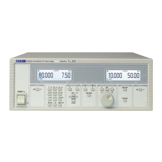
- Page 1 QPX600D & DP PowerFlex+ Dual DC Power Supplies...
-
Page 2: Table Of Contents
Table of Contents Specification Safety Installation Connections Initial Operation Manual Operation – Independent Mode Manual Operation – Link Modes Maintenance Remote Operation Remote Commands (QPX600DP only) Note: The latest revisions of this manual, device drivers and software tools can be downloaded from: http://www.aimtti.com/support. -
Page 3: Specification
Resolution: 1mV (60V Range), 2mV (80V Range) Accuracy: 0.1% of setting ± 2mV, (± 4mV on 80V range) Current Setting: Resolution 10mA QPX600D & DP Accuracy: 0.3% of setting ± 20mA Power Envelope (per channel) Operating Mode: Constant voltage or constant current... - Page 4 METER SPECIFICATIONS (Each Output) Display Type: 5-digit (Volts), 4-digit (Amps), black-on-white backlit LCD. Voltage Resolution 1mV (CC Mode and Unreg): Accuracy: 0.1% of reading ± 2 digits Current Resolution 10mA (CV Mode and Unreg): Accuracy: 0.3% of reading ± 2 digits V x A: Resolution 0·1W Accuracy: 0·5% ±...
- Page 5 KEYBOARD & ROTARY CONTROL All functions, including the selection and set-up of the remote control interfaces, can be set from the keyboard. The rotary Jog control can be used to adjust output voltage and current settings in a quasi-analogue mode. The output to be controlled is first selected with the appropriate Control key. DISPLAY FEATURES The displays (one for each output) are graphic LCDs, backlit by white LEDs;...
-
Page 6: Safety
Safety This power supply is a Safety Class I instrument according to IEC classification and has been designed to meet the requirements of EN61010-1 (Safety Requirements for Electrical Equipment for Measurement, Control and Laboratory Use). It is an Installation Category II instrument intended for operation from a normal single phase supply. -
Page 7: Installation
Installation Mains Operating Voltage This instrument has a universal input range and will operate from a nominal 115V or 230V mains supply without adjustment. Check that the local supply meets the AC Input requirement given in the Specification. Mains Lead Connect the instrument to the AC supply using the mains lead provided. -
Page 8: Connections
Connections Rear Panel Connections Output Terminals (each output) The load should be connected to the positive (red) and negative (black) terminals marked OUTPUT. The terminals accept 4mm plugs into the end (but note that 4mm plugs will only support 30 Amps), 6mm diameter wire or plugs into the cross-hole or 8mm spade connections (with a maximum blade width of 16mm). - Page 9 Analogue Monitor (each output) The output terminal voltage and output current may be monitored on V MONITOR and I MONITOR respectively. The output scaling for both is the same as that set for V CONTROL and I CONTROL, see previous section. The Analogue Monitor outputs should be connected to a measuring system with ‘floating’...
-
Page 10: Initial Operation
Initial Operation This section of the manual is a general introduction to the controls and operation of the instrument and is intended to be read before using the power supply for the first time. In this manual front panel keys, connections and indicators are shown in capitals, e.g. ESCAPE, JOG SET, OUTPUT, ON. - Page 11 Pressing SHIFT illuminates the ▲ lamp and gives the numeric keys the functions marked above them, e.g. STR (Store), RCL (Recall), etc. When a shift function is selected SHIFT is cancelled (the ▲ lamp is no longer lit). The further key presses required to complete the selected function are described in detail in the sections that follow;...
-
Page 12: Manual Operation - Independent Mode
Manual Operation – Independent Mode New users should first read the Initial Operation chapter which describes the operating principles of the keypad and rotary jog control. The default mode at power-up is ‘Tracking Off’, i.e. the two outputs are fully independent. The following sections describe operation of either output in this mode. - Page 13 The default position at power-up is under the LSD, i.e. the lowest jog increment is selected. The jog steps that can be selected are 1mV (2mV for the 0-80V range), 10mV and 100mV. With jog enabled the output voltage can be incremented or decremented with the rotary jog control with a step resolution indicated by the position of the JOG indicator.
- Page 14 Power Limit The maximum current at different voltage settings is limited by the power envelope illustrated below: QPX600D & DP Power Envelope The power envelope is set to give 80V/7.5A and 10V/50A under all supply conditions (both outputs loaded); at lower output voltages the output power is restricted by the 50A current maximum.
- Page 15 Connection to the Load The load should be connected to the positive (red) and negative (black) OUTPUT terminals. Both are fully floating and either can be connected to ground. Warning! Voltages above 70Vdc are hazardous live according to EN 61010-1 and great care must be taken when using the power supply at voltages above this level.
- Page 16 It should be noted that the unit can only source current and cannot sink it, thus units cannot be series connected in anti-phase. The unit can be connected in parallel with others to produce higher currents. Where several units are connected in parallel, the output voltage will be equal to that of the unit with the highest output voltage setting until the current drawn exceeds its current limit setting, upon which the output will fall to that of the next highest setting, and so on.
- Page 17 Output Protection In addition to OVP and OCP for forward over-voltage and over-current protection, the output is protected from reverse voltages by a diode; the continuous reverse current must not exceed 3 Amps although transients can be much higher. Temperature Trip and Other Faults If the safe internal temperature limit is exceeded because, for example, the fan vents have been blocked, the output is automatically tripped off.
- Page 18 Store Settings The instrument can store 10 set-ups in non-volatile memory; the parameters stored are voltage, current limit, OVP and OCP. The output state and remote sense setting are not stored. To store a set-up press SHIFT, STORE to show the store locations and the currently saved set-ups on the screen.
- Page 19 # Code Function Output always off at power-up (factory default) Output status at power-up same as at last power-down LOGIC OUT 'closed' for Output ON, 'open' for Output OFF (factory default) LOGIC OUT ‘closed' for Output OFF, 'open' for Output ON LOGIC OUT ‘closed’...
-
Page 20: Manual Operation - Link Modes
Manual Operation – Link Modes In addition to independent output operation, described in the Manual Operation – Independent Mode chapter, the instrument is capable of operating in a number of different tracking modes which can be activated from the LINK MENU. If either output is under analogue control then pressing ‘LINK MENU’... -
Page 21: Maintenance
Maintenance The Manufacturers or their agents overseas will provide a repair service for any unit developing a fault. Where owners wish to undertake their own maintenance work, this should only be done by skilled personnel in conjunction with the service manual which may be purchased directly from the Manufacturers or their agents overseas. -
Page 22: Remote Operation
Remote Operation The QPX600DP can be remotely controlled via its RS232, USB, GPIB, LAN or Analogue interfaces; the QPX600D has Analogue interfaces only. USB remote control operates in a similar way to RS232 but via the USB connector. Software supplied with the instrument sets up the controlling computer to treat the USB connection as a virtual COM port. - Page 23 Sending any command from an interface without control privileges that attempts to change the instrument status will set bit 4 of the Standard Event Status Register and put 200 into the Execution Error Register to indicate that there are not sufficient privileges for the required action. Note: it is also possible to configure the privileges for a particular interface to either ‘read only’...
- Page 24 RS232 Character Set Because of the need for XON/XOFF handshake it is possible to send ASCII coded data only; binary blocks are not allowed. Bit 7 of ASCII codes is ignored, i.e. assumed to be low. No distinction is made between upper and lower case characters in command mnemonics and they may be freely mixed.
- Page 25 cannot be found a static IP address of 192.168.0.100 is assigned. Resetting the LAN removes any password protection. For more information on LXI standards refer to www.lxistandard.org/home . LAN Connection To use the LAN interface, the IP address of the unit must be known. . On the supplied CD-ROM is a guide to the LXI Discovery Tool which provides links to the latest version of the tool and associated downloads.
- Page 26 VXI-11 Discovery Protocol The instrument has very limited support of VXI-11 which is sufficient for the discovery protocol and no more. The instrument implements a Sun RPC Port-mapper on TCP port 111 and UDP port 111 as defined in RPC1183. The calls supported are: NULL, GET PORT and DUMP. On TCP port 1024 a very simple VXI-11 protocol is implemented sufficient only for instrument discovery.
- Page 27 Source Handshake Acceptor Handshake Talker Listener Service Request Remote Local Parallel Poll Device Clear Device Trigger Controller Electrical Interface Query Error Register - GPIB IEEE Std. 488.2 Error Handling The IEEE 488.2 error (addressed to talk with nothing to say) is handled as follows. UNTERMINATED If the instrument is addressed to talk and the response formatter is inactive and the input queue is empty then the...
- Page 28 bit 7 = don't care bit 6 = bit 5 = Parallel poll enable bit 4 = bit 3 = Sense sense of the response bit; 0 = low, 1 = high bit 2 = bit 1 = bit position of the response bit 0 = Example.
- Page 29 Bit 7 - Power On. Set when power is first applied to the instrument. Bit 6 - Not used. Bit 5 - Command Error. Set when a syntax type error is detected in a command from the bus. The parser is reset and parsing continues at the next byte in the input stream. Bit 4 - Execution Error.
- Page 30 Bit 7 - Reserved for future use Bit 6 - Set when a fault trip has occurred which requires AC power OFF/ON to reset. Bit 5 - Set when an output sense trip has occurred Bit 4 - Set when an output over current trip has occurred Bit 3 - Set when an output over voltage trip has occurred Bit 2 -...
- Page 31 Status Model Power on Settings The following instrument status values are set at power on: Status Byte Register Service Request Enable Register † Standard Event Status Register = 128 (pon bit set) Standard Event Status Enable Register † Execution Error Register Query Error Register Parallel Poll Enable Register †...
-
Page 32: Remote Commands (Qpx600Dp Only)
Remote Commands (QPX600DP only) Remote Command Format RS232 input to the instrument is buffered in a 256 byte input queue which is filled, under interrupt, in a manner transparent to all other instrument operations. The instrument will send XOFF when approximately 200 characters are in the queue. - Page 33 is ignored except in command identifiers. e.g. '*C LS' is not equivalent to '*CLS'. <WHITE SPACE> is defined as character codes 00H to 20H inclusive with the exception of the NL <WHITE SPACE> character (0AH). The high bit of all characters is ignored. The commands are case insensitive. Operating Modes There are five operating modes for the instrument (listed in the following table) of which four may be selected under digital remote control.
- Page 34 Instrument Specific Commands For commands specified as 'WITH VERIFY' the operation is completed when the parameter being adjusted reaches the required value to within ±5% or ±10 counts, whichever is the greater. If the value fails to settle within these limits within 5 seconds then the Verify Timeout bit (bit 3) is set in the Standard Event Status Register and the operation is completed at the end of timeout period.
- Page 35 OPALL < > Simultaneously sets all outputs on/off where < > has the following meaning: 0=ALL OFF, 1=ALL ON. If OPALL sets all outputs ON then any that were already on will remain ON If OPALL sets all outputs OFF then any that were already off will remain OFF SENSE<...
- Page 36 *PRE < > Set the Parallel Poll Enable Register to the value < >. *PRE? Report the value in the Parallel Poll Enable Register. The response is < 1>< >. *SRE < > Sets the Service Request Enable Register to < >...
- Page 37 NETMASK? Returns the present netmask of the LAN interface, provided it is connected. The response is nnn.nnn.nnn.nnn< >, where each nnn is 0 to 255. NETCONFIG? Returns the first means by which an IP address will be sought. The response is < ><...
- Page 38 Thurlby Thandar Instruments Ltd. Glebe Road • Huntingdon • Cambridgeshire • PE29 7DR • England (United Kingdom) Telephone: +44 (0)1480 412451 • Fax: +44 (0)1480 450409 International web site: www.aimtti.com • UK web site: www.aimtti.co.uk Email: info@aimtti.com Aim Instruments and Thurlby Thandar Instruments...
Need help?
Do you have a question about the QPX600D and is the answer not in the manual?
Questions and answers