Table of Contents
Advertisement
Advertisement
Table of Contents

Related Manuals for Aim-TTI MX100T


Summary of Contents for Aim-TTI MX100T
- Page 1 MX100T & MX100TP Triple Output Multi-Range DC Power Supply INSTRUCTION MANUAL...
-
Page 2: Table Of Contents
CONTENTS Product Description ......................4 Safety ..........................5 Installation ........................6 Mains Operating Voltage ..................6 Mains Lead .......................6 Mounting ........................6 Ventilation .........................6 Connections ........................7 Front Panel Connections ..................7 Rear Panel Connections (MX100TP) ...............7 Terminal Voltages and Safety...................7 Output Protection ......................7 Initial Operation ......................8 AC Power On/Off ......................8 DC Output On/Off .....................8 The Display and Soft Key Control ................9... - Page 3 Changing System Preferences ................20 10.1 Status at Power-up ....................20 10.2 Alert Sound (Beep) ....................20 10.3 Spin Wheel Action ....................20 Notes on Operation ....................21 11.1 Accuracy and Resolution ..................21 11.2 Remote Sense ....................21 11.3 Parallel Wiring of Outputs ..................
- Page 4 Using this Manual This manual includes cross references which are shown as follows - see section X.X. Within a PDF file, the shaded number is a hyperlink to that section number which enables the user to jump rapidly to the section referred to and then jump back to continue reading the original section.
-
Page 5: Product Description
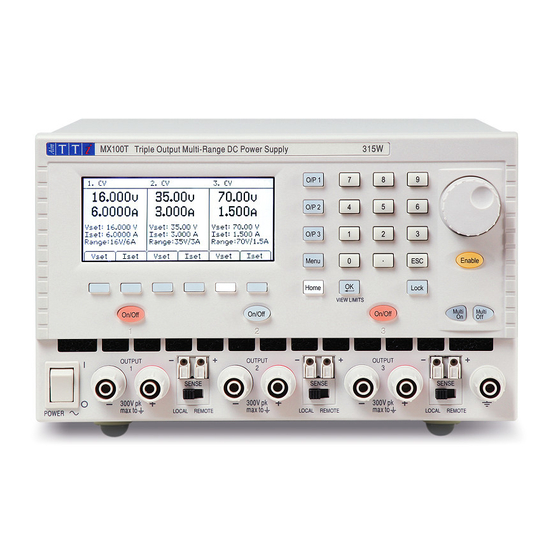
Product Description The MX100T is a triple output laboratory power supply incorporating three outputs of similar power and features. Each output can provide 0 to 35 volts at 0 to 3 amps (105 watts) with range switching extending its capabilities to provide voltages up to 70V and currents up to 6A. Twelve range combinations are available as shown in the chart. -
Page 6: Safety
Safety This power supply is a Safety Class I instrument according to IEC classification and has been designed to meet the requirements of EN61010-1 (Safety Requirements for Electrical Equipment for Measurement, Control and Laboratory Use). It is an Installation Category II instrument intended for operation from a normal single phase supply. -
Page 7: Installation
Installation 4.1 Mains Operating Voltage This instrument has a universal input range and will operate from a nominal 115V or 230V mains supply without adjustment. Check that the local supply meets the AC Input requirement given in the Specification see section 17. 4.2 Mains Lead Connect the instrument to the AC supply using the mains lead provided. -
Page 8: Connections
5.2 Rear Panel Connections (MX100TP) The MX100T has only an AC power connection socket on the rear panel. The MX100TP has duplicate power and sense terminals on the rear panel and offers full remote control capabilities through USB, RS232, GPIB and LAN interfaces. -
Page 9: Initial Operation
Initial Operation 6.1 AC Power On/Off Power The AC power switch is located at the bottom left of the front panel. At power-up a screen is displayed that shows the firmware revision number and a brief description of the starting conditions. These can be changed from System Preferences if required –... -
Page 10: The Display And Soft Key Control
The Display and Soft Key Control With the exception of output On/Off, the primary control of the power supply is via the six keys directly below the display. These are referred to as “soft keys” because their function is not fixed but is annotated by legends on the display directly above. -
Page 11: Setting With The Keypad
7.3 Setting with the Keypad Vset & Iset Voltage or current can be set using the numeric keypad. Upon pressing a numeric key, the OK key will start to flash. When the numeric value entry is completed, pressing OK causes the value to be accepted and actioned. -
Page 12: Power Supply Settings
Power Supply Settings The procedures for setting voltage and current, either numerically or via the spin wheel, have been explained in the previous section. 8.1 CV and CC modes, Viewing Settings (Limits) Depending upon the load conditions, the actual voltage and actual current applying to the load will not both be equal to their set values. -
Page 13: Power Display (Vxa)
8.3 Power Display (VxA) The power being supplied to the load (VxA) is displayed in watts on the lower right hand side. The value is calculated from the metered values of voltage and current and is displayed with a maximum resolution of 0.001 watts for output 1 and 0.01 watts for outputs 2 and 3. 8.4 Selecting Current Meter Averaging Iavg Current meter averaging is useful when the load current is varying rapidly. -
Page 14: Setting The Voltage/Current Range
8.6 Setting the Voltage/Current Range Range Each output has more than one range. For output 1 the choice is 35V/3A or 16V/6A. For output 2 the choice is 35V/3A, 16V/6A or 35V/6A. For output 3 the choice is 35V/3A, 70V/1.5A or 70V/3A. -
Page 15: The System Menu Screen
8.8 The System Menu Screen The operation of the System Menu screen is selected with the key marked Menu which illuminates when pressed. System menu functions are described within section 9 - Advanced Functions. 8.9 Voltage Tracking The power supply can be set-up such that the voltage of output 2 tracks that of output 1, or that output 3 tracks output 2, or that outputs 2 and 3 both track output 1. -
Page 16: Display Symbols
Display Symbols Some functions are indicated by symbols or abbreviation on the display as follows: Function Home Screen Individual Output Screen Output on, constant voltage CV shown on the top line CV shown on the top line mode next to the output number Output on, constant current CC shown plus flashing CC shown plus flashing... -
Page 17: Menu - Advanced Functions
10 Menu - Advanced Functions Menu Pressing the key marked Menu selects the System Menu screen. This provides access to advanced options and functions. When the system menu is displayed, setting of output parameters is not possible but operation of the output On/Off keys is unaffected. -
Page 18: Current Meter Averaging Setup
10.2 Current Meter Averaging Setup Menu > Current Meter Averaging Setup The degree of averaging of the current meter reading when Iavg is turned on (see section 7.4) can be set individually for each output. The System Menu function “Current Meter Averaging Setup” provides an individual choice of low, medium or high (Low, Medium, High) for each of the three outputs set via the soft keys. -
Page 19: Emergency Off
At ex-factory defaults, the On and Off delays are all set to Quick causing them to respond immediately to the key press. The Tab arrow keys move through the On and Off states for the outputs which can be changed using the soft keys. -
Page 20: System Preferences
10.6 System Preferences Menu > System Preferences Various aspects of the power supply operation can be changed from the System Preferences function. These are detailed in section 10. 10.7 Setting to Factory Defaults Menu > Factory Defaults This function can be used to return most of the instrument settings including Voltage, Current, Range, OVP, OCP, Output On/Off, Current Meter Averaging, Multi-On/Off Action and System Preferences back to the factory default values as listed in section 18. -
Page 21: Changing System Preferences
11 Changing System Preferences Menu > System Preferences Access to System Preferences is selected from the main system menu. A listing of system preferences is shown. The current system preferences are indicated by ticks against the relevant setting. Changes are made by moving the highlight with either the arrow keys or the spin wheel and pressing the Select soft key. -
Page 22: Notes On Operation
12 Notes on Operation 12.1 Accuracy and Resolution All three outputs provide good accuracy and resolution and offer remote sensing to ensure precise regulation at the load. See section 17 for accuracy specifications. Output 1 offers greater resolution and accuracy than outputs 2 and 3 and uses 5 digit meters to give 1mV and 0.1mA resolution (as against 10mV and 1mA for outputs 2 and 3). -
Page 23: Series Wiring Of Outputs
12.4 Series Wiring of Outputs If voltages above 70 volts are required, this can be achieved by wiring two or more outputs in series. For example, outputs 1, 2 and 3 could be series connected to provide up to 140V. Voltages up to 115V could be achieved by connecting all three outputs in series and selecting voltage tracking so that full voltage adjustments can be made using one output control. -
Page 24: Using Ovp And Ocp
increased if the current setting is very low or is very close to the current required by the load. A large external capacitance at the load could also slow down the response. When switching off with no load, the output will normally fall back to zero within a fixed length of time (see section 17 –... -
Page 25: Remote Interface Operation (Mx100Tp Only)
13 Remote Interface Operation (MX100TP only) 13.1 MX100TP Rear Panel Connections Output Connections The Output and Sense terminals are duplicated on the rear panel terminal block marked Output +, Output -, Sense + and Sense -. These connections are paralleled with their front panel equivalents. -
Page 26: Gpib Interface
The LAN interface is designed to meet LXI (Lan eXtensions for Instrumentation) version 1.4 LXI Core 2011. Remote control using the LAN interface is possible using the TCP/IP Sockets protocol. The instrument also contains a basic Web server which provides information on the unit and allows it to be configured from a web browser. -
Page 27: Usb Interface And Device Driver Installation
13.2.3 USB Interface and Device Driver Installation The instrument firmware can be updated in the field through the USB port. This does not need the driver described here. It requires a PC software utility provided by the manufacturer, and uses a HID driver that will already be installed on the PC. If that is the only USB functionality required, download the package containing the firmware update together with the PC utility from the manufacturer, and follow the instructions included. -
Page 28: Lan Ip Address And Hostname
Since it is possible to misconfigure the LAN interface, making it impossible to communicate with the instrument over LAN, a LAN Configuration Initialise (LCI) mechanism is provided via a push switch (marked LAN RESET) accessible through a small hole in the rear panel. This restores the default configuration with DHCP enabled, so the unit will then follow the sequence described in the previous paragraph. -
Page 29: Interface Locking
LXI Discovery Tool This tool can be used to display the IP addresses and other associated information of all connected devices that comply with the VXI-11 discovery protocol. It is a Windows PC application, which is provided on the supplied CD ROM that can be installed and run on the controlling PC, with the unit either connected directly to the PC network connector or via a router. -
Page 30: Status Reporting
interface instance that currently has the lock, and may be queried from any interface by sending an “IFLOCK?” command. The reply to this query will be “-1” if the lock is owned by another interface instance, “0” if the interface is free and “1” if the lock is owned by the requesting interface instance. - Page 31 Bit 7 - Reserved for future use Bit 6 - Set when a fault trip has occurred which requires AC power OFF/ON to reset. Bit 5 - Reserved for future use Bit 4 - Reserved for future use Bit 3 - Set when an output over current trip has occurred Bit 2 - Set when an output over voltage trip has occurred...
- Page 32 The Execution Error Register is read and cleared using the ‘EER?’ command. On power up this register is set to 0 for all interface instances. There is no corresponding mask register: if any of these errors occurs, then bit 4 of the Standard Event Status Register will be set.
- Page 33 usually hold a response from the instrument until the controlling software reads it; there is no equivalent of the GPIB state ‘addressed to talk’, so the instrument is not aware of the actions of the controller The IEEE 488.2 UNTERMINATED error arises if the instrument is addressed to talk and has nothing to say, because the response formatter is inactive and the input queue is empty.
- Page 34 Status Model Page 33...
-
Page 35: Remote Commands (Mx100Tp Only)
14 Remote Commands (MX100TP only) 14.1 General 14.1.1 Remote and Local Operation At power-on the instrument will be in the local state, with normal keyboard operation possible. All remote interfaces are active and listening for a remote command. When any command is received from any interface the instrument will enter the remote state. -
Page 36: Command Timing
< > numbers must be in basic units, may have a decimal point and fractional part, and can include an exponent part if helpful. They are rounded to the precision supported by the instrument. 14.1.4 Command Timing There are no dependent parameters, coupled parameters, overlapping commands, expression program data elements or compound command program headers. - Page 37 OVP< >? Return the voltage trip setting of output < >. Response is VP< > < 2>< > where < 2> is in Volts. Note: If over voltage protection has been disabled the response is VP< > < >< > where < >...
-
Page 38: Common Commands
CONFIG < > Sets the voltage tracking mode of the unit to < > where < > has the following meaning: 0 = None. 1 = Mode1. 2 = Mode2. 3 = Mode3. These modes are as defined within the Setting Voltage Tracking section of this manual –... -
Page 39: Status Commands
*OPC Sets the Operation Complete bit (bit 0) in the Standard Event Status Register. This will happen immediately the command is executed because of the sequential nature of all operations. *OPC? Query Operation Complete status. The response is always 1< >... -
Page 40: Interface Management Commands
14.2.4 Interface Management Commands LOCAL Go to local. Any subsequent command will restore the remote state. IFLOCK Set or Clear the lock requiring the instrument to respond only to this < > interface, where < > has the meaning: 0 = clear and 1 = set the lock. It is an Execution Error (number 200) if the request is denied either because of conflict with a lock on this or another interface, or the user has disabled this interface from taking control using the web interface. -
Page 41: Maintenance
15 Maintenance The Manufacturers or their agents overseas will provide a repair service for any unit developing a fault. Where owners wish to undertake their own maintenance work, this should only be done by skilled personnel in conjunction with the Service Guide, which may be purchased directly from the Manufacturers or their agents overseas. -
Page 42: Technical Specifications
16 Technical Specifications General specifications apply for the temperature range 5°C to 40°C. Accuracy specifications apply for the temperature range 18°C to 28°C after 15 minutes warm-up with no load and calibration at 23°C. Typical specifications are determined by design and are not guaranteed. OUTPUT SPECIFICATIONS (Each Output) Voltage/Current O/P1: Switchable 0V to 35V/0.1mA to 3A or 0V to16V/0.1mA to 6A... - Page 43 Output Protection: Output will withstand an applied forward voltage of up to 50V (O/P1 and O/P2), or 80V O/P3. Reverse protection by diode clamp for reverse currents up to 3A. Over-voltage Protection Outputs 1 and 2: 1V to 40V. Output 3: 1V to 80V. Output trips off for OVP. (OVP) Trip: Resolution 100mV.
- Page 44 INTERFACES (MX100TP only) Full digital remote control facilities are available through the USB, RS232, LAN and GPIB interfaces. Setting and readback resolutions are the same as for the Output and Meter specifications respectively. RS232: Standard 9-pin D-connector. Baud rate 9600. USB: Standard USB 2.0 hardware connection.
-
Page 45: Default Values
17 Default Values When supplied from the factory the power supply is set as follows: All Outputs Voltage 1 volt Current 0.1 amp Range 35V/3A 40V (O/P1 and O/P2); 80V (O/P3) 7A (O/P1 and O/P2); 3.5A (O/P3) Current meter averaging Off (Level = Medium) Voltage tracking None...
Need help?
Do you have a question about the MX100T and is the answer not in the manual?
Questions and answers