Table of Contents
Advertisement
Quick Links
Advertisement
Table of Contents

Related Manuals for Aim-TTI MX100Q


Summary of Contents for Aim-TTI MX100Q
- Page 1 MX100Q & MX100QP Triple Output Multi-Range DC Power Supply INSTRUCTION MANUAL...
-
Page 2: Table Of Contents
CONTENTS Product Description ......................3 Range Combinations ....................4 Safety ..........................5 Installation ........................6 Mains Operating Voltage ..................6 Mains Lead .......................6 Mounting ........................6 Ventilation .........................6 Connections ........................7 Front Panel Connections ..................7 Rear Panel Connections (MX100QP) ...............7 Terminal Voltages and Safety...................8 Output Protection ......................8 Initial Operation ......................9 Switching On ......................9 Keyboard ........................9... - Page 3 10.2 Remote Sense ....................21 10.3 Parallel Wiring of Outputs ..................21 10.4 Series Wiring of Outputs ..................22 10.5 Instantaneous Current Output ................22 10.6 Output On/Off and Response Speed ..............22 10.7 Using OVP and OCP ................... 23 10.7.1 OCP Trip at Output On ..................23 10.8 Over-temperature Trip (OTP) ................
-
Page 4: Product Description
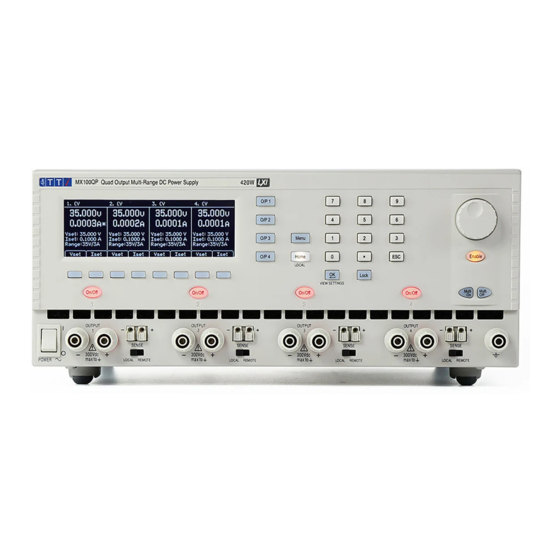
The power supply is housed in a ¾ rack width, 3U high case with front input ventilation. An intelligent fan is used to minimise cooling noise. The MX100Q P version has the same manual control features and adds USB, RS232, GPIB (Optional) and LXI compliant LAN interfaces together with duplicate power and sense terminals at the rear. -
Page 5: Range Combinations
1.1 Range Combinations Output 1 Output 2 Output 3 Output 4 35V/3A 35V/3A 35V/3A 35V/3A 16V/6A 35V/3A 35V/3A 35V/3A 35V/3A 16V/6A 35V/3A 35V/3A 16V/6A 16V/6A 35V/3A 35V/3A 16V/6A 16V/6A 70V/1.5A 35V/3A 16V/6A 16V/6A 35V/3A 70V/1.5A 16V/6A 16V/6A 70V/1.5A 70V/1.5A 35V/3A 16V/6A 70V/1.5A 70V/1.5A... -
Page 6: Safety
Safety This power supply is a Safety Class I instrument according to IEC classification and has been designed to meet the requirements of EN61010-1 (Safety Requirements for Electrical Equipment for Measurement, Control and Laboratory Use). It is an Installation Category II instrument intended for operation from a normal single phase supply. -
Page 7: Installation
In a rack-mounted situation, when using the recommended Aim-TTi rack mount (RM460), no additional space is required above or to the sides of the unit. Some air space below the unit will ensure the best possible airflow and the lowest fan speeds for a given power but is not required. -
Page 8: Connections
C- The grey terminal marked with an Earth symbol is connected to the chassis and safety earth ground. 4.2 Rear Panel Connections (MX100QP) D- The MX100Q has only an AC power connection socket on the rear panel. The MX100QP also has: E- Power and sense terminals... -
Page 9: Terminal Voltages And Safety
Output Connections The Output and Sense terminals are duplicated on the rear panel terminal block marked Output +, Output -, Sense + and Sense -. These connections are paralleled with their front panel equivalents. Switch the front panel LOCAL/REMOTE switch to REMOTE when remote sensing is required. When the rear panel output terminals are used, the use of remote sense is always recommended to ensure that output regulation is maintained within specification;... -
Page 10: Initial Operation
Initial Operation 5.1 Switching On 1- Power At power-up a screen is displayed that shows the firmware revision number and a brief description of the starting conditions. These can be changed from System Preferences if required – see section 9.1. 5.2 Keyboard The front panel contains the liquid crystal display (LCD) and the keyboard which are used together to control all instrument functions. - Page 11 5- Display control keys There are five main screens which are selected by the keys. The selected key is illuminated. (Home) displays all four outputs simultaneously, (Menu) provides access to advanced functions, (O/P n) show more detailed information for each individual output. Note: If an output is disabled, an error beep will occur and the output screen is unavailable.
-
Page 12: Display
5.3 Display The Home Screen The Home screen shows the primary information for all four outputs simultaneously whilst enabling voltage and current to be set for any output. The display is divided into four sections representing outputs 1, 2 ,3 and 4 from left to right. -
Page 13: Setting With Individual Output Screens
To draw attention to the CC symbol and make it clear at a glance, a flashing arrow is placed next to it. It is also possible to set an audible alert – see section 9.2. Output Off When an output is off, the meters show these set values and SET is shown on the top line of the display. -
Page 14: Setting Over-Voltage And Over-Current Protection
6.5 Setting Over-Voltage and Over-Current protection OVP/OCP The power supply offers user adjustable over-voltage protection (OVP) and over-current protection (OCP). If a voltage is detected that exceeds the OVP level, or a current is detected that exceeds the OCP level, the output is switched off and the message OVP or OCP is displayed. -
Page 15: Store And Recall Of Settings
6.7 Store and Recall of Settings Stores Each output has 50 memory stores capable of storing range, voltage, current, OVP and OCP. Pressing the Stores soft key brings up a menu screen which shows the present contents of the memories from which settings can be stored or recalled. -
Page 16: Display Symbols
Display Symbols Some functions are indicated by symbols or abbreviation on the display as follows: Function Home Screen Individual Output Screen Output on, constant voltage CV shown on the top line CV shown on the top line mode next to the output number Output on, constant current CC shown plus flashing CC shown plus flashing... -
Page 17: Menu - Advanced Functions
Menu - Advanced Functions Menu Pressing the key marked Menu selects the System Menu screen. This provides access to advanced options and functions. When the system menu is displayed, setting of output parameters is not possible but operation of the output On/Off keys is unaffected. -
Page 18: Current Meter Averaging Setup
8.2 Current Meter Averaging Setup Menu > Current Meter Averaging Setup The degree of averaging of the current meter reading when Iavg is turned on (see section 6.4) can be set individually for each output. The System Menu function “Current Meter Averaging Setup” provides an individual choice of low, medium or high (Low, Medium, High) for each of the four outputs set via the soft keys. -
Page 19: Emergency Off
At ex-factory defaults, the On and Off delays are all set to Quick causing them to respond immediately to the key press. The Tab arrow keys move through the On and Off states for the outputs which can be changed using the soft keys. -
Page 20: System Preferences
8.6 System Preferences Menu > System Preferences Various aspects of the power supply operation can be changed from the System Preferences function. These are detailed in section 9. 8.7 Setting to Factory Defaults Menu > Factory Defaults This function can be used to return most of the instrument settings including Voltage, Current, Range, OVP, OCP, Output On/Off, Current Meter Averaging, Multi-On/Off Action and System Preferences back to the factory default values as listed in section Error! Reference source not found.. -
Page 21: Changing System Preferences
Changing System Preferences Menu > System Preferences Access to System Preferences is selected from the main system menu. A listing of system preferences is shown. The current system preferences are indicated by ticks against the relevant setting. Changes are made by moving the highlight with either the arrow keys or the spin wheel and pressing the Select soft key. -
Page 22: Notes On Operation
10 Notes on Operation 10.1 Accuracy and Resolution All four outputs provide good accuracy and resolution and offer remote sensing to ensure precise regulation at the load. See section 14 for accuracy specifications. Ranges 16V and 35V offer greater resolution and accuracy than 70V range and uses 5-digit meters to give 1mV and 0.1mA resolution (as against 10mV and 0.1mA for 70V range). -
Page 23: Series Wiring Of Outputs
10.4 Series Wiring of Outputs If voltages above 70 volts are required, this can be achieved by wiring two or more outputs in series. For example, outputs 1, 2, 3 and 4 could be series connected to provide up to 140V. Voltages up to 140V can also be achieved by connecting outputs 3 and 4 (in 70V range with outputs 1 and 2 disabled) in series and selecting voltage tracking so that full voltage adjustments can be made using one output control. -
Page 24: Using Ovp And Ocp
However, this time could be increased if the current setting is very low or is very close to the current required by the load. A large external capacitance at the load could also slow down the response. When switching off with no load, the output will normally fall back to zero within a fixed length of time (see section 14 –... -
Page 25: Remote Interface Operation (Mx100Qp Only)
Failure or Over-temperature’ message screen will be displayed. If poor ventilation is suspected, correct the problem, allow the instrument to cool, and use the Reset soft-key to re-initialise the instrument. However, if the ‘Hardware Failure or Over-temperature’ message screen continues to be displayed after the instrument has cooled and been restarted, there may be a component fault;... -
Page 26: Rs232 Interface
11.1.2 RS232 Interface The 9-way D-type serial interface connector is located on the instrument rear panel. It should be connected to a standard PC port preferably using a fully wired 9 way 1:1 male-female cable without any cross-over connections. Alternatively, a 3-way cable can be used, connecting only pins 2, 3 and 5 to the PC, but with links made in the connector at the PC end between pins 1, 4 and 6 and between pins 7 and 8, as shown in the diagram: Most commercial cables provide these connections. -
Page 27: Lan Interface
If this happens, select this device, right click and choose “update driver software...” and then “browse this computer for driver software...” and then locate the .INF file on the CD as described above. Once Windows has installed the device driver it will assign a COM port number to this particular unit. -
Page 28: Lan Ip Address And Hostname
11.1.5 LAN IP Address and Hostname To communicate with the instrument through the LAN interface, the IP address (which was allocated during the connection procedure described above) must be known. Once connected and correctly configured, the IP address of the unit is displayed within the Remote Control Interfaces screen (Menu >... -
Page 29: Interface Locking
Once a link has been created anything written to the device is ignored and any attempt to read from the device returns the same identification string as the *IDN? query. VISA Resource Name Because of the limited support for VXI-11 (Discovery Protocol only), the instrument must be referred to by its raw socket information when used with software packages which communicate using a VISA resource name. - Page 30 The full set of error and status registers and the individual bits they contain is shown in the Status Model Diagram and described in detail below, but in brief the status is maintained using five primary registers, the Limit Event Status Register for each output, the Standard Event Status Register and the Execution Error Register.
- Page 31 Bit 4 Execution Error. Set when a non-zero value is written to the Execution Error register, if a syntactically correct command cannot be executed for any reason. Bit 3 Verify Timeout Error. Set when a parameter is set with 'verify' specified and the value is not reached within 5 secs, e.g.
- Page 32 Bit 6 MSS/RQS. This bit (as defined by IEEE Std. 488.2) contains alternatively the Master Status Summary message returned in response to the *STB? query, or the Requesting Service message returned in response to a Serial Poll. The RQS message is cleared when polled, but the MSS bit remains set for as long as the condition is true.
- Page 33 The IEEE 488.2 INTERRUPTED error arises if the response formatter is waiting to send a response message and a <PROGRAM MESSAGE TERMINATOR> has been read by the parser, or the input queue contains more than one END message. This will cause the Query Error bit to be set in the Standard Event Status Register, a value of 1 to be placed in the Query Error Register and the response formatter to be reset, discarding the waiting response message.
- Page 34 Status Model Page 33...
-
Page 35: Remote Commands (Mx100Qp Only)
12 Remote Commands (MX100QP only) 12.1 General 12.1.1 Remote and Local Operation At power-on the instrument will be in the local state, with normal keyboard operation possible. All remote interfaces are active and listening for a remote command. When any command is received from any interface the instrument will enter the remote state. -
Page 36: Command Timing
< > numbers must be in basic units, may have a decimal point and fractional part, and can include an exponent part if helpful. They are rounded to the precision supported by the instrument. 12.1.4 Command Timing There are no dependent parameters, coupled parameters, overlapping commands, expression program data elements or compound command program headers. - Page 37 I< >? Return the set current limit of output < >. Response is I< > < 2>< > where < 2> is in Amps. OVP< >? Return the voltage trip setting of output < >. Response is VP< > < 2><...
-
Page 38: Common Commands
VRANGE< >? Returns the voltage range for output< >. The response is < 1>< > where < 1> has the following meaning: Output1: 0= Disable, 1= 35V/3A, 2 = 16V/6A, 3 = 35V/6A. Output2: 0= Disable, 1= 35V/3A, 2 = 16V/6A, 3 = 35V/6A. -
Page 39: Status Commands
*RCL < > Recall the settings for all four outputs simultaneously from the store specified by < > where < > can be 0-49. This includes output On/Off state, current meter averaging state, and the Multi-On/Multi-Off settings. *OPC Sets the Operation Complete bit (bit 0) in the Standard Event Status Register. -
Page 40: Interface Management Commands
12.2.4 Interface Management Commands LOCAL Go to local. Any subsequent command will restore the remote state. IFLOCK Set or Clear the lock requiring the instrument to respond only to this < > interface, where < > has the meaning: 0 = clear and 1 = set the lock. It is an Execution Error (number 200) if the request is denied either because of conflict with a lock on this or another interface, or the user has disabled this interface from taking control using the web interface. -
Page 41: Maintenance
13 Maintenance The Manufacturers or their agents overseas will provide a repair service for any unit developing a fault. Where owners wish to undertake their own maintenance work, this should only be done by skilled personnel in conjunction with the Service Guide, which may be purchased directly from the Manufacturers or their agents overseas. -
Page 42: Technical Specifications
14 Technical Specifications General specifications apply for the temperature range 5°C to 40°C. Accuracy specifications apply for the temperature range 18°C to 28°C after 15 minutes warm-up with no load and calibration at 23°C. Typical specifications are determined by design and are not guaranteed. OUTPUT SPECIFICATIONS (Each Output) Voltage/Current O/P1: 0V to 35V/0.1mA to 3A or 0V to16V/0.1mA to 6A... - Page 43 Voltage Programming Maximum time required for output to settle within 1% of its total excursion Speed MX100QP only: (for resistive load). Excludes command processing time. (Typical figures) 90% Load No Load 90% Load No Load 35V 3A 10ms 10ms Down 60ms 550ms 16V 6A...
- Page 44 Indoor use at altitudes up to 2000m, Pollution Degree 2. Safety: Complies with EN61010-1. EMC: Complies with EN61326. Size: 320 x 130 x 375mm (WxHxD) x 3U height. Weight: 7.3kg (MX100Q) 7.5 kg (MX100QP) Options: 19-inch rack kit. Page 43...
-
Page 45: Default Values
15 Default Values When supplied from the factory the power supply is set as follows: All Outputs Voltage 1 volt Current 0.1 amp Range 35V/3A 40V (O/P1 and O/P2); 80V (O/P3 and 4) 7A (O/P1 and O/P2); 3.5A (O/P3 and 4) Current meter averaging Off (Level = Medium) Voltage tracking... - Page 46 Glebe Road • Huntingdon • Cambridgeshire • PE29 ?DR • England (United Kingdom) Telephone: +44 (0)1480 412451 • Fax: +44 (0)1480 450409 International web site: www.aimtti.com • UK web site: www.aimtti.co.uk • USA web site: www.aimtti.us Email: info@aimtti.com Aim & Thurlby Thandar Instruments (Aim-TTi)
Need help?
Do you have a question about the MX100Q and is the answer not in the manual?
Questions and answers