
Related Manuals for Aim-TTI MX100Q


Summary of Contents for Aim-TTI MX100Q
- Page 1 INSTRUCTION MANUAL INSTRUCTION MANUAL MX100Q/QP & MX103Q/QP Quad Output Laboratory Power Supply...
-
Page 2: Table Of Contents
1 - Product Description Product Description ........................4 Power Capability................................4 Available Ranges ................................4 Safety ............................. 5 Symbols ..................................5 Safety Notices ................................6 Installation ............................. 7 Mains Operating Voltage ............................. 7 Mains Lead ................................... 7 Mounting ..................................7 Ventilation .................................. - Page 3 1 - Product Description Store and Recall of Settings for All Outputs ......................19 Multi-On / Multi-Off Operation and Sequencing ..................... 20 Setting TripLink OVP/ OCP ............................21 Pass Code Locking of the Front Panel ........................21 System Preferences ..............................22 Setting to Factory Defaults ............................
- Page 4 1 - Product Description Maintenance ...........................47 Cleaning ..................................47 Fuse ..................................... 47 Calibration .................................. 47 Firmware Update (MX-P only) ........................... 47 Technical Specifications ......................48 Default Values ........................51 Appendix 1: ..........................52 Setting the Voltage/Current Range in Compatibility Mode ..................52 The latest revisions of this manual, device drivers, and software tools can be downloaded from: http://www.aimtti.com/support MX-Q &...
-
Page 5: Product Description
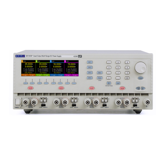
The power supply is housed in a ¾ rack width, 3U high case with front input ventilation. An intelligent fan is used to minimise cooling noise. The MX100Q & MX103Q P version has the same manual control features and adds USB, RS232, GPIB (Optional), and LXI-compliant LAN interfaces together with duplicate power and sense terminals at the rear. -
Page 6: Safety
2 - Safety SAFETY Symbols This instruction manual contains information and warnings which must be followed by the user to ensure safe operation and to retain the instrument in a safe condition. The following symbols are displayed on the instrument and throughout the manual, to ensure the safety of the user and the instrument, all information must be read before proceeding. -
Page 7: Safety Notices
2 - Safety Safety Notices This instrument is: · A safety Class I instrument according to IEC classification and has been designed to meet the requirements of EN61010-1 (Safety Requirements for Electrical Equipment for Measurement, Control and Laboratory Use). It is an Installation Category II instrument intended for operation from a normal single-phase supply. -
Page 8: Installation
In a rack-mounted situation, when using the recommended Aim-TTi rack mount (RM460), no additional space is required above or to the sides of the unit. Some air space below the unit will ensure the best possible airflow and the lowest fan speeds for a given power but is not required. -
Page 9: Instrument Overview
300VDC; the maximum permissible voltage between either terminal of one output and either terminal of another output on the same power supply is also 300VDC. Exceeding the maximum reverse voltage (40V [80V for MX100Q OP3 & 4]) and current (3A) will damage the unit... - Page 10 4 - Instrument Overview ③ ④ ⑤ ⑥ ② ① ① AC power inlet Connect to AC mains using the power lead provided. See ‘Mains Lead’ for more details. ② Power and sense NOTE Image shows the protective cover in place as supplied by the manufacturer. terminals The Output and Sense terminals are duplicated on the rear panel terminal block marked Output +, Output -, Sense + and Sense -.
-
Page 11: Getting Started
5 - Getting Started GETTING STARTED Using this manual This section is a general introduction to the operation of the instrument and is intended to In this manual front panel, keys and sockets are shown in capitals, e.g., ON, OFF. Text and be read before using the Power Supply for the first time. -
Page 12: Display
5 - Getting Started Display The Home Screen The Home screen shows the primary information for all four outputs simultaneously whilst enabling voltage and current to be set for any output. ① ② ③ ④ ⑤ 1 (orange), 2 (green), 3 (blue), 4 (pink) ①... -
Page 13: Initial Operation
(1mV/0.1mA for 16V and 35V ranges, or 10mV/0.1mA for 70V range on MX100Q/P). When the spin wheel is rotated more rapidly the rate of increment is increased, enabling the value to be changed quickly. The action of the spin wheel can be changed from System Preferences to reduce the speed-related increment rate if preferred. -
Page 14: Setting With Individual Output Screens
The value is calculated from the metered values of voltage and current and is displayed with a maximum resolution of 0.001 watts; and 0.01 watts for outputs 3 and 4 in 70V range on the MX100Q/P model. Selecting Current Meter Averaging Iavg Current meter averaging is useful when the load current is varying rapidly. -
Page 15: Setting Over-Voltage And Over-Current Protection
(OCP). If a voltage is detected that exceeds the OVP level, or a current is detected that exceeds the OCP level, the output is switched off and the message OVP or OCP is displayed. The OVP and OCP values are shown in the table below: MX100Q/P MX103Q/P Output 1V to 40V 0.01A to 7A... -
Page 16: Setting The Voltage/Current Range
5 - Getting Started Setting the Voltage/Current Range Range Each output has more than one range: MX100Q/P MX103Q/P O/P 1 O/P 2 O/P 3 O/P4 O/P 1 O/P 2 O/P 3 O/P 4 35V/3A 16V/6A 70V/1.5A 16V/6A 35V/6A 70V/3A 35V/6A Pressing the Range soft key brings up a menu screen which indicates the currently selected range and output with a flashing arrow. -
Page 17: Store And Recall Of Settings
5 - Getting Started Store and Recall of Settings Stores Each output has 50 memory stores capable of storing range, voltage, current, OVP and OCP. Pressing the Stores soft key brings up a menu screen which shows the present contents of the memories from which settings can be stored or recalled. -
Page 18: Ovp /Ocp Triplink
Link symbol shown between the Master and Slave Voltage set above 60V High voltage symbol after High voltage symbol (MX100Q /QP in 70V range) voltage value after voltage value Multi-On/Multi-Off not set to Clock symbol on top line Clock symbol on top... -
Page 19: Menu - Advanced Functions
6 - Menu - Advanced Functions MENU - ADVANCED FUNCTIONS Menu Pressing the key marked Menu selects the System Menu screen, providing access to advanced options and functions. Each item of the system menu is selected by using the two arrow keys, or by turning the spin wheel until the desired line is highlighted, and then pressing the Select soft key. -
Page 20: Current Meter Averaging Setup
6 - Menu - Advanced Functions Current Meter Averaging Setup Menu > Current Meter Averaging Setup The degree of averaging of the current meter reading when Iavg is turned on can be set The System Menu function “Current Meter Averaging Setup” provides an individual individually for each output. -
Page 21: Multi-On / Multi-Off Operation And Sequencing
6 - Menu - Advanced Functions Multi-On / Multi-Off Operation and Sequencing Menu > Multi-On/Multi-Off Setup The two keys on the bottom right-hand side marked Multi-On and Multi-Off control the On and Off behaviour for all four outputs. By default, these keys provide a synchronous On/Off capability whereby all four outputs are turned The System Menu function “Multi-On/Multi-Off Setup”... -
Page 22: Setting Triplink Ovp/ Ocp
6 - Menu - Advanced Functions Setting TripLink OVP/ OCP Menu > TripLink OCP Menu > TripLink OVP Trip Link is a feature that allows the OVP and OCP protection trips of one output to be linked to other outputs. If a trip occurs, all linked outputs will be tripped simultaneously. TripLink OVP and TripLink OCP are set in the same way. -
Page 23: System Preferences
6 - Menu - Advanced Functions System Preferences Menu > System Preferences Various aspects of the power supply operation can be changed from the System Preferences function. These are detailed in ‘Changing System Preferences’. Setting to Factory Defaults Menu > Factory Defaults This function can be used to return most of the instrument settings including Voltage, Current, Range, OVP, OCP, TripLink, Output On/Off, Current Meter Averaging, Multi-On/Off Action and System Preferences back to the factory default values as listed in section ‘12’... -
Page 24: Changing System Preferences
7 - Changing System Preferences CHANGING SYSTEM PREFERENCES Menu > System Preferences Access to System Preferences is selected from the main system menu. A list of system preferences is shown. The current system preferences are indicated by ticks against the relevant setting. -
Page 25: Notes On Operation
See ‘Technical Specifications’ for accuracy specifications. On the MX100Q/P model, ranges 16V and 35V offer greater resolution and accuracy than 70V range and uses 5-digit meters to give 1mV and 0.1mA resolution (as against 10mV and 0.1mA for 70V range). -
Page 26: Parallel Wiring Of Outputs
8 - Notes on Operation Parallel Wiring of Outputs If currents above 6 amps are required, this can be achieved by wiring two or more outputs in parallel. For example, outputs 1 and 2 could be paralleled to provide 16V/12A. In this situation it would be appropriate to use voltage tracking (Mode1 V2=V1 in this example) so that the voltage can be adjusted directly on one output. -
Page 27: Series Wiring Of Outputs
For example, outputs 1, 2, 3 and 4 could be series connected to provide up to 140V. If using the MX100Q/P model, Voltages up to 140V can also be achieved by connecting outputs 3 and 4 in series and selecting voltage tracking so that full voltage adjustments can be made using one output control. -
Page 28: Instantaneous Current Output
8 - Notes on Operation Instantaneous Current Output The current setting control can be set to limit the continuous output current to levels down to the milliamps. However, in common with all precision bench power supplies, a capacitor is connected across the output to maintain stability and good transient response. This capacitor charges to the output voltage and short-circuiting of the output will produce a current pulse as the capacitor discharges which is independent of the current limit setting. -
Page 29: Using Ovp And Ocp
8 - Notes on Operation Using OVP and OCP OVP (over-voltage protection) monitors the voltage on the output terminals and switches the output off if it exceeds the OVP setting. The response speed is typically 100us. Control of OVP is described in ‘Setting Over-Voltage and Over-Current protection’. OVP might be used to guard against accidental mis-setting of the power supply or might be used to identify a fault condition when operating in constant current mode. -
Page 30: Remote Interface Operation (Mx-P Versions Only)
9 - Remote Interface Operation (MX-P Versions only) REMOTE INTERFACE OPERATION (MX-P VERSIONS ONLY) Remote Interface Configuration The MX100QP and MX103QP models can be remotely controlled via its USB, LAN, RS232 or GPIB (Optional). The USB interface enumerates as a Communications Class device and interacts with application software through a standard virtual COM port device driver on the PC. - Page 31 9 - Remote Interface Operation (MX-P Versions only) RS232 Interface The 9-way D-type serial interface connector is located on the instrument rear panel. It should be connected to a standard PC port preferably using a fully wired 9 way 1:1 male- female cable without any cross-over connections.
- Page 32 9 - Remote Interface Operation (MX-P Versions only) USB Interface and Device Driver Installation The instrument firmware can be updated in the field through the USB port. This does not need the driver described here. It requires a PC software utility provided by the manufacturer and uses a HID driver that will already be installed on the PC.
- Page 33 9 - Remote Interface Operation (MX-P Versions only) LAN Interface The LAN interface is designed to comply with the LXI standard version 1. LXI Core 2016 and contains the interfaces and protocols described below. For more information on LXI standards refer to www.lxistandard.org. When powered up and attached to a network, the unit will by default attempt to obtain IP address and netmask settings via DHCP, or, if DHCP times out (after 30 seconds), via Auto- IP.
- Page 34 9 - Remote Interface Operation (MX-P Versions only) Web Server and Configuration Password Protection The unit contains a basic web server. This provides information on the instrument and allows it to be configured. The Configure and Instrument Control pages can be password protected to deter unauthorised changes to the remote operation configuration;...
- Page 35 9 - Remote Interface Operation (MX-P Versions only) XML Identification Document URL As required by the LXI standard, the instrument provides an XML identification document that can be queried via a GET at “http://IPaddress:80/lxi/identification” that conforms to the LXI XSD Schema (available at http://www.lxistandard.org/InstrumentIdentification/1.0 ) and the W3C XML Schema Standards ( http://www.w3.org/XML/Schema ).
- Page 36 9 - Remote Interface Operation (MX-P Versions only) Having a separate status model for each interface instance ensures that data does not get lost, as some status query commands (e.g., ‘*ESR?’) clear the contents of a register after reading the present value. The full set of error and status registers and the individual bits they contain is shown in the Status Model Diagram and described in detail below, but in brief the status is maintained using five primary registers, the Limit Event Status Register for each output, the Standard...
- Page 37 9 - Remote Interface Operation (MX-P Versions only) Standard Event Status Registers (ESR and ESE) The Standard Event Status Register is defined by the IEEE Std. 488.2 GPIB standard. It is a bit field, where each bit is independent and has the following significance: Bit 7 Power On.
- Page 38 9 - Remote Interface Operation (MX-P Versions only) There is no corresponding mask register: if any of these errors occurs, then bit 4 of the Standard Event Status Register will be set. This bit can be masked from any further consequences by clearing bit 4 of the Standard Event Status Enable Register.
- Page 39 9 - Remote Interface Operation (MX-P Versions only) and PPD commands in the manner defined by the standard. The instrument implements passive pull-up on the DIO lines during Parallel Poll. Query Error Register - GPIB IEEE Std. 488.2 Error Handling These errors are much more likely to occur on the semi-duplex GPIB interface, which requires the instrument to hold a response until addressed to talk by the controller.
- Page 40 9 - Remote Interface Operation (MX-P Versions only) Register Summary Query Name LSR1?, LSR2?, LSR3?,LSR4? Limit Status Registers LSE1, LSE2, LSE1?, LSE2?, LSE3?, LSE4? Limit Status Enable Registers LSE3, LSE4 † EER? Execution Error Register † QER? Query Error Register †...
- Page 41 9 - Remote Interface Operation (MX-P Versions only) Status Model MX-Q & MX-QP Series 2 Instruction Manual...
-
Page 42: Remote Commands (Mx- P Versions Only)
10 - Remote Commands (MX- P versions only) REMOTE COMMANDS (MX- P VERSIONS ONLY) General Remote and Local Operation At power-on the instrument will be in the local state, with normal keyboard operation possible. All remote interfaces are active and listening for a remote command. When any command is received from any interface the instrument will enter the remote state. -
Page 43: Command List
10 - Remote Commands (MX- P versions only) parameter, but any other additional < > is ignored. Note that the Backspace WHITE SPACE character (07H) is treated as < >, so it cannot be used to delete incorrect WHITE SPACE characters, and will not hide the error. - Page 44 10 - Remote Commands (MX- P versions only) Instrument Function Commands V<n> <nrf> Set output < > to < > Volts. V<n>V <nrf> Set output < > to < > Volts with verify. OVP<n> <nrf> Set output < > over voltage protection trip point to < >...
- Page 45 10 - Remote Commands (MX- P versions only) VRANGE<n> <nrf> Set output< > voltage range to < > where < > has the following meaning: Output1: 0= Disable, 1= 35V/3A, 2 = 16V/6A, 3 = 35V/6A. Output2: 0= Disable, 1= 35V/3A, 2 = 16V/6A, 3 = 35V/6A. Output3: 0= Disable, 1= 35V/3A, 2 = 70V/1.5A, 3 = 70V/3A.
- Page 46 10 - Remote Commands (MX- P versions only) Common Commands *IDN? Returns the instrument identification. The response is in the form <NAME>, <model>, <serial>, <version>< > where <NAME> is the manufacturer's name, <model> is the instrument type, <serial> is the interface serial number and <version>...
- Page 47 10 - Remote Commands (MX- P versions only) Interface Management Commands LOCAL Go to local. Any subsequent command will restore the remote state. IFLOCK < > Set or Clear the lock requiring the instrument to respond only to this interface, where <...
- Page 48 11 - Maintenance MAINTENANCE The Manufacturers or their agents overseas will provide a repair service for any unit developing a fault. Where owners wish to undertake their own maintenance work, this should only be done by skilled personnel in conjunction with the Service Guide, which may be purchased directly from the Manufacturers or their agents overseas.
- Page 49 18°C to 28°C after 15 minutes warm-up with no load and calibration at 23°C. Typical specifications are determined by design and are not guaranteed. OUTPUT SPECIFICATIONS (Each Output) MODELS MX100Q MX103Q OUTPUT Voltage and Max power per...
- Page 50 35V 6A 10ms 10ms Down 20ms 1400ms MODELS MX100Q MX103Q Output will withstand an applied Output will withstand an applied forward voltage of up to 50V (O/P1, forward voltage of up to 50V. Reverse Output Protection: O/P2), or 80V (O/P3, O/P4). Reverse...
- Page 51 Indoor use at altitudes up to 2000m, Pollution Degree 2. Safety: Complies with EN61010-1. EMC: Complies with EN61326. Size: 320 x 130 x 375mm (WxHxD) x 3U height. Weight: 7.3kg (MX100Q) 7.5 kg (MX100QP) Options: 19-inch rack kit. MX-Q & MX-QP Series 2 Instruction Manual...
- Page 52 13 - Default Values EXTRAS MODELS MX100Q MX103Q TripLink -OCP Max TripLink time- <400ms TripLink -OVP Max TripLink time- <300ms Allows up to 210 watts from a single output (105 watts O/P4 on the MX103Q/QP), Powershare power is dynamically shared across the outputs, based on the set voltage and current.
- Page 53 14 - Appendix 1: APPENDIX 1: Setting the Voltage/Current Range in Compatibility Mode Selecting a high-power setting, e.g. 35V/6A will require the disabling of other outputs, see the following table for range combinations. Pressing the Range soft key brings up a menu screen which indicates the currently selected range and output with a flashing arrow.
- Page 54 70V/3A* 35V/6A 70V/3A* 70V/3A* 70V/3A* *MX100Q /QP only The previous manual ‘MX100Q & MX100QP Instruction Manual (P/N 48511-1820 issue 2)’ contains the remote commands for this mode, this can be found at www.aimtti.co.uk MX-Q & MX-QP Series 2 Instruction Manual...
- Page 55 EXCELLENCE THROUGH EXPERIENCE Aim-TTi is the trading name of Thurlby Thandar Instruments Ltd. (TTi), one of Europe’s leading manufacturers of test and measurement instruments. The company has wide experience in the design and manufacture of advanced test instruments and power supplies built up over more than thirty years.
Need help?
Do you have a question about the MX100Q and is the answer not in the manual?
Questions and answers