Table of Contents
Advertisement
Quick Links
Advertisement
Table of Contents

Related Manuals for Aim-TTI MX180T


Summary of Contents for Aim-TTI MX180T
- Page 1 MX180T & MX180TP Triple Output Multi-Range DC Power Supply INSTRUCTION MANUAL...
-
Page 2: Table Of Contents
CONTENTS Product Description ......................4 Safety ..........................5 Installation ........................6 Mains Operating Voltage ..................6 Mains Lead .......................6 Mounting ........................6 Ventilation .........................6 Connections ........................7 Front Panel Connections ..................7 Rear Panel Connections (MX180TP) ...............7 Terminal Voltages and Safety...................7 Output Protection ......................7 Initial Operation ......................8 AC Power On/Off ......................8 DC Output On/Off .....................8 The Display and Soft Key Control ................9... - Page 3 Changing System Preferences ................20 10.1 Status at Power-up ....................20 10.2 Alert Sound (Beep) ....................20 10.3 Spin Wheel Action ....................20 Notes on Operation ....................21 11.1 Remote Sense ....................21 11.2 Instantaneous Current Output ................21 11.3 Output On/Off and Response Speed ..............
- Page 4 Using this Manual This manual includes cross references which are shown as follows - see section X.X. Within a PDF file, the shaded number is a hyperlink to that section number which enables the user to jump rapidly to the section referred to and then jump back to continue reading the original section.
-
Page 5: Product Description
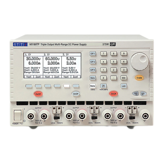
Product Description The MX180T is a triple output laboratory power supply incorporating three high performance outputs offering exceptional versatility within its total power capability of more than 375 watts. The two main outputs offer 0 to 30 volts at 0 to 6 amps, but can alternatively be switched to provide 15V/10A or 60V/3A. -
Page 6: Safety
Safety This power supply is a Safety Class I instrument according to IEC classification and has been designed to meet the requirements of EN61010-1 (Safety Requirements for Electrical Equipment for Measurement, Control and Laboratory Use). It is an Installation Category II instrument intended for operation from a normal single phase supply. -
Page 7: Installation
Installation 3.1 Mains Operating Voltage This instrument has a universal input range and will operate from a nominal 115V or 230V mains supply without adjustment. Check that the local supply meets the AC Input requirement given in the Specification see section 17. 3.2 Mains Lead Connect the instrument to the AC supply using the mains lead provided. -
Page 8: Connections
4.2 Rear Panel Connections (MX180TP) The MX180T has only an AC power connection socket on the rear panel. The MX180TP has duplicate power and sense terminals on the rear panel and offers full remote control capabilities through USB, RS232, GPIB and LAN interfaces. -
Page 9: Initial Operation
Initial Operation 5.1 AC Power On/Off Power The AC power switch is located at the bottom left of the front panel. At power-up a screen is displayed that shows the firmware revision number and a brief description of the starting conditions. These can be changed from System Preferences if required –... -
Page 10: The Display And Soft Key Control
The Display and Soft Key Control With the exception of output On/Off, the primary control of the power supply is via the six keys directly below the display. These are referred to as “soft keys” because their function is not fixed but is annotated by legends on the display directly above. -
Page 11: Setting With The Keypad
6.3 Setting with the Keypad Vset & Iset Voltage or current can be set using the numeric keypad. Upon pressing a numeric key, the OK key will start to flash. When the numeric value entry is completed, pressing OK causes the value to be accepted and actioned. -
Page 12: Power Supply Settings
Power Supply Settings The procedures for setting voltage and current, either numerically or via the spin wheel, have been explained in the previous section. 7.1 CV and CC modes, Viewing Settings (Limits) Depending upon the load conditions, the actual voltage and actual current applying to the load will not both be equal to their set values. -
Page 13: Power Display (Vxa)
7.3 Power Display (VxA) The power being supplied to the load (VxA) is displayed in watts on the lower right hand side. The value is calculated from the metered values of voltage and current and is displayed with a maximum resolution of 0.001 watts for outputs 1 and 2, and 0.01 watts for output 3. 7.4 Selecting Current Meter Averaging Iavg Current meter averaging is useful when the load current is varying rapidly. -
Page 14: Setting The Voltage/Current Range
7.6 Setting the Voltage/Current Range Range Each output has more than one range. For outputs 1 and 2 the choices are 30V/6A, 15V/10A or 60V/3A. For output 3 the choice is 5.5V/3A or 12V/1.5A. Additionally output 1 has 4 further ranges that provide up to 360 watts from a single output as 30V/12A, 15V/20A, 60V/6A or 120V/3A. -
Page 15: The System Menu Screen
jump directly to a location by entering a two digit number (e.g. 07 or 45). Unused memory locations are shown by the word Empty. Pressing the Store key writes the present settings of the output into the selected memory location. If the position already has settings stored within it a confirmation is required. Pressing the Recall key transfers the stored settings of the selected memory location to the output. -
Page 16: Display Symbols
Display Symbols Some functions are indicated by symbols or abbreviation on the display as follows: Function Home Screen Individual Output Screen Output on, constant voltage CV shown on the top line CV shown on the top line mode next to the output number Output on, constant current CC shown plus flashing CC shown plus flashing... -
Page 17: Menu - Advanced Functions
Menu - Advanced Functions Menu Pressing the key marked Menu selects the System Menu screen. This provides access to advanced options and functions. When the system menu is displayed, setting of output parameters is not possible but operation of the output On/Off keys is unaffected. -
Page 18: Store And Recall Of Settings For All Outputs
9.3 Store and Recall of Settings for All Outputs Menu > Stores: All Outputs (Store/Recall) Each output has its own set of 50 memories in which settings can be stored for that output (see section 7.8). A further set of 50 memories is provided that allow the user to store and recall the settings status for all three outputs simultaneously. -
Page 19: Emergency Off
Delay sets a time value in milliseconds between 10ms and 20,000ms (20 seconds) using the spin wheel. Never removes an output completely from control by the Multi-On or Multi-Off key. Quick returns to immediate response. Note that any previously set delay value is retained when set to Quick or Never and is restored when Delay is selected again. -
Page 20: Setting To Factory Defaults
9.7 Setting to Factory Defaults Menu > Factory Defaults This function can be used to return most of the instrument settings including Voltage, Current, Range, OVP, OCP, Output On/Off, Current Meter Averaging, Multi-On/Off Action and System Preferences back to the factory default values as listed in section 18. Note that it is possible that a request to set factory defaults will fail to complete if it invokes certain range changes, see section 7.6 for more information. -
Page 21: Changing System Preferences
10 Changing System Preferences Menu > System Preferences Access to System Preferences is selected from the main system menu. A listing of system preferences is shown with the alternative condition(s) appearing directly above or below within the list. The current system preferences are indicated by ticks against the relevant setting. -
Page 22: Notes On Operation
11 Notes on Operation 11.1 Remote Sense Each output has a very low output impedance, but this is inevitably increased by the resistance of the connecting leads and the contact resistance between terminals and leads. At high currents this can result in significant differences between the indicated source voltage and the actual load voltage (two 20 milliohm connecting leads will drop 0.2V at 5 Amps, for example). -
Page 23: Using Ovp And Ocp
Turn-on and turn-off speeds are particularly relevant to Multi-On/Multi-Off output sequencing (see section 9.4) where delays between the switching of different outputs can be set to a resolution of 10ms. These delays apply only to the initiation of an output being turned on or turned off, the actual delay will depend upon the actual turn-on or turn-off times applying as described above. -
Page 24: Remote Interface Operation (Mx180Tp Only)
12 Remote Interface Operation (MX180TP only) 12.1 MX180TP Rear Panel Connections Output Connections The Output and Sense terminals are duplicated on the rear panel terminal block marked Output +, Output -, Sense + and Sense -. These connections are paralleled with their front panel equivalents. -
Page 25: Gpib Interface
The LAN interface is designed to meet LXI (Lan eXtensions for Instrumentation) version 1.4 LXI Core 2011. Remote control using the LAN interface is possible using the TCP/IP Sockets protocol. The instrument also contains a basic Web server which provides information on the unit and allows it to be configured from a web browser. -
Page 26: Usb Interface And Device Driver Installation
12.2.3 USB Interface and Device Driver Installation The instrument firmware can be updated in the field through the USB port. This does not need the driver described here. It requires a PC software utility provided by the manufacturer, and uses a HID driver that will already be installed on the PC. If that is the only USB functionality required, download the package containing the firmware update together with the PC utility from the manufacturer, and follow the instructions included. -
Page 27: Lan Ip Address And Hostname
Since it is possible to misconfigure the LAN interface, making it impossible to communicate with the instrument over LAN, a LAN Configuration Initialise (LCI) mechanism is provided via a push switch (marked LAN RESET) accessible through a small hole in the rear panel. This restores the default configuration with DHCP enabled, so the unit will then follow the sequence described in the previous paragraph. -
Page 28: Interface Locking
LXI Discovery Tool This tool can be used to display the IP addresses and other associated information of all connected devices that comply with the VXI-11 discovery protocol. It is a Windows PC application, which is provided on the supplied CD ROM that can be installed and run on the controlling PC, with the unit either connected directly to the PC network connector or via a router. -
Page 29: Status Reporting
interface instance that currently has the lock, and may be queried from any interface by sending an “IFLOCK?” command. The reply to this query will be “-1” if the lock is owned by another interface instance, “0” if the interface is free and “1” if the lock is owned by the requesting interface instance. - Page 30 Bit 7 - Reserved for future use Bit 6 - Set when a fault trip has occurred which requires AC power OFF/ON to reset. Bit 5 - Reserved for future use Bit 4 - Reserved for future use Bit 3 - Set when an output over current trip has occurred Bit 2 - Set when an output over voltage trip has occurred...
- Page 31 Range Change Error: An operation requiring a range change was requested but could not be completed. Typically this occurs because >0.5V was still present on output 1 and/or output 2 terminals at the time the command was executed; see 7.6. Access Denied: an attempt was made to change the instrument’s settings from an interface which is locked out of write privileges by a lock held by another interface.
- Page 32 Query Error Register - GPIB IEEE Std. 488.2 Error Handling These errors are much more likely to occur on the semi-duplex GPIB interface, which requires the instrument to hold a response until addressed to talk by the controller. All the other interfaces provide full duplex communication, with buffering in the physical layer which will usually hold a response from the instrument until the controlling software reads it;...
- Page 33 Standard Event Status *ESE *ESE? Enable Register *STB? Status Byte Register Status Byte Enable *SRE *SRE? Register Parallel Poll Response *PRE *PRE? Enable Register Status Model Page 32...
-
Page 34: Remote Commands (Mx180Tp Only)
13 Remote Commands (MX180TP only) 13.1 General 13.1.1 Remote and Local Operation At power-on the instrument will be in the local state, with normal keyboard operation possible. All remote interfaces are active and listening for a remote command. When any command is received from any interface the instrument will enter the remote state. -
Page 35: Command Timing
< > numbers must be in basic units, may have a decimal point and fractional part, and can include an exponent part if helpful. They are rounded to the precision supported by the instrument. 13.1.4 Command Timing There are no dependent parameters, coupled parameters, overlapping commands, expression program data elements or compound command program headers. - Page 36 OVP< >? Return the voltage trip setting of output < >. Response is VP< > < 2>< > where < 2> is in Volts. Note: If over voltage protection has been disabled the response is VP< > < >< > where < >...
-
Page 37: Common Commands
CONFIG < > Sets the voltage tracking mode of the unit to < > where < > has the following meaning: 0 = Disabled. 1 = Enabled. CONFIG? Returns the voltage tracking mode of the unit. The response is < 1><... -
Page 38: Status Commands
*TRG The product has no trigger capability. The command is ignored in this instrument. † Note: this command potentially requires a range change that may not be possible because >0.5V is still present on either output 1 or output 2 terminals at the time the command is executed;... - Page 39 IFLOCK? Query the status of the interface lock. The response is: < 1>< > where < 1> is = 0 if there is no active lock, = 1 if this interface instance owns the lock or = -1 if the lock is unavailable either because it is in use by another interface or the user has disabled this interface from taking control (via the web interface).
-
Page 40: Maintenance
14 Maintenance The Manufacturers or their agents overseas will provide a repair service for any unit developing a fault. Where owners wish to undertake their own maintenance work, this should only be done by skilled personnel in conjunction with the Service Guide, which may be purchased directly from the Manufacturers or their agents overseas. -
Page 41: Technical Specifications
15 Technical Specifications General specifications apply for the temperature range 5°C to 40°C. Accuracy specifications apply for the temperature range 18°C to 28°C after 15 minutes warm-up with no load and calibration at 23°C. Typical specifications are determined by design and are not guaranteed. OUTPUT SPECIFICATIONS (Each Output) Voltage/Current O/P1: Switchable 0V to 30V/1mA to 6A, 0V to15V/1mA to 10A... - Page 42 Over-current Protection Measure-and-compare OCP for all outputs. OCP trips output off; typical (OCP) Trip: response time 500ms. Setting range: O/P1 0.1A – 22A, O/P2 0.1A – 12A, O/P3 0.1A – 3.5A. Setting resolution: 10mA. Accuracy: ± (0.3% ±2digits) Over-temperature The output will be tripped off if a fault or blocked ventilation causes the Protection (OTP) Trip: internal temperature to rise excessively.
-
Page 43: Default Values
VOLTAGE TRACKING The power supply can be set so that the voltage of O/P2 is automatically set to that of O/P1 and tracks any changes. INTERFACES (MX180TP only) Full digital remote control facilities are available through the USB, RS232, LAN and GPIB interfaces. Setting and readback resolutions are the same as for the Output and Meter specifications respectively.
Need help?
Do you have a question about the MX180T and is the answer not in the manual?
Questions and answers