Table of Contents
Advertisement
Advertisement
Table of Contents

Related Manuals for Allegion Interflex IF-171


Summary of Contents for Allegion Interflex IF-171
- Page 3 Copyright © 2016 Version: September 23, 2016 Interflex Datensysteme GmbH Allegion Zettachring 16 D-70567 Stuttgart, Germany Tel.: +49 (0711) 1322 0 Internet Email: interflex.info@allegion.com Website: http://www.interflex.de Interflex operates as a part of Allegion plc. For more information on Allegion, please visit www.allegion.com.
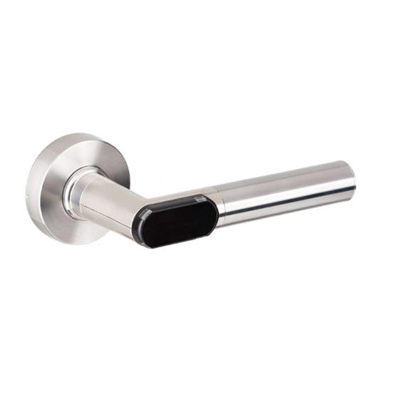
- Page 4 About this Document This operating and assembly manual describes the electronic IF-171 door handle in rosette fitting (in short: IF-171). It is part of the product and contains important information that is necessary for proper operation and maintenance. This operating and assembly manual applies to all variants of the IF-171 door handle. Please thoroughly read through this operating and assembly manual to ensure failure-free and secure operations.
- Page 5 The documentation has been written for persons that install and commission the devices described in this documentation. Warnings, symbols and designations Warnings warn against hazards that may arise when using the devices described in the document. The hazard levels can be identified by the signal word: Signal word Meaning Identifies a hazard that may result in severe personal...
-
Page 7: Table Of Contents
Contents Contents Notes on Safety Warnings ..........................1 Fire Protection, Escape and Emergency Escape Routes ............ 1 Emergency Facilities ......................1 Environments Exposed to Explosion Hazards ..............2 Important Instructions and Guidelines regarding Batteries ..........2 Maintenance Always with Open Door .................. 2 Electrostatic Discharge (ESD) ..................... - Page 8 Contents Outline of Parameterization of »NetworkOnCard« in Interflex Access Control Systems ..27 Credentials and booking types ...................27 3.4.1 Credential authentication ..................28 3.4.2 Creating credentials: the read/write unit ..............28 3.4.3 Deactivate Cards ....................28 3.4.4 Sequence lock (optional) ..................28 Opening doors........................29 3.5.1 Opening the door with a credential ................29 3.5.2 Activating/deactivating the permanently open mode ..........29...
-
Page 9: Notes On Safety
1 Notes on Safety Electronic components for access control play an important role in the security concept of your organization. These components must be properly installed, regularly maintained and inspected to ensure that they do not fail. Please observe the following notes on safety prior to the installation and maintenance work. 1.1 Warnings Warnings warn against hazards that may arise when using the devices described in the document. -
Page 10: Environments Exposed To Explosion Hazards
Notes on Safety 1.4 Environments Exposed to Explosion Hazards Do not use products that are not explicitly approved for areas exposed to explosion hazards in areas exposed to such hazards! 1.5 Important Instructions and Guidelines regarding Batteries Please adhere to the basic rules for using batteries: Only use the specified batteries. -
Page 11: Retrofitting Procedure
Notes on Safety Protective measures Therefore, please perform maintenance work in an ESD-protected environment, if possible: ESD-compliant flooring. ESD-compliant shoes, protective gloves and outerwear. ESD-compliant work surfaces with conductive mats as surfaces. ESD-compliant tools. ESD-compliant personal protective grounding during activities when sitting, e. g. wrist grounding ... -
Page 13: The Electronic If-171 Door Handle
The Electronic IF-171 Door Handle 2 The Electronic IF-171 Door Handle Use the electronic IF-171 door handle to secure access to rooms. The door handle is equipped with credential electronics that allow persons with valid credentials to open the door with the IF-171 door handle. -
Page 14: Intended Use
The Electronic IF-171 Door Handle 2.1.1 Intended Use The electronic IF-171 door handle is intended to be installed in building doors and for opening the doors. It is compatible with the commonly used European standards for locks. The different versions allow it to be used in all the common doors such as wood, steel and aluminum doors as well as doors with narrow frames having a backset of more than 30 mm. -
Page 15: Design
The Electronic IF-171 Door Handle Event logging can be enabled or disabled for each door handle individually, to be able to comply with specific data privacy guidelines. 2.1.5 Design Design for Door with Electronic Authorization on One Side Mechanical door handle Electronic door handle Locking screw Reading unit... -
Page 16: Door Handle: Variants
The Electronic IF-171 Door Handle 2.1.6 Door Handle: Variants Different handle shapes and versions are available: Door handles in L-shape or U-shape One or two-sided electronic authorization For doors hinged on the right or left For inside or outside use ... -
Page 17: Installation
The Electronic IF-171 Door Handle 2.2 Installation 2.2.1 Assembly Instructions Mounting screws that are too long can damage the door handle! The rosette of the electronic door handle can be damaged if the mounting screws are too long! Please note the following instructions before you start with the assembly: It is absolutely necessary that you carry out the assembly with the door open. -
Page 18: Design For Door With Electronic Authorization On One Side
The Electronic IF-171 Door Handle 2.2.4 Design for Door with Electronic Authorization on One Side Insert the square pin of the electronic door handle into the square nut of the lock. Slip drilling template onto the square pin. Align the drilling template horizontally. Mark the holes. - Page 19 The Electronic IF-171 Door Handle Insert the handle holder of the mechanical door handle from the other side and screw it along with the electronic door handle through the door panel. Please use the supplied mounting screws. Attach the mechanical door handle. Hold the door handle horizontally during this process. Tighten the rosette towards the left for door handles pointing to the right and guide it over the handle holder;...
-
Page 20: Design For Door With Electronic Authorization On Both Sides
The Electronic IF-171 Door Handle 2.2.5 Design for Door with Electronic Authorization on Both Sides Insert the square pin of the outer electronic door handle into the square nut of the lock. Slip drilling template onto the square pin. Align the drilling template horizontally. Mark the holes. -
Page 21: Assembling The Key Rosette
The Electronic IF-171 Door Handle Screw together both electronic door handles through the door panel. Please use the supplied mounting screws. Attach the rosette cover. Insert the battery to operate the door handle. Close the housing. To operate the door handle, insert the battery and close the housing. Check the functionality and easy movement of the door handle with the door open. -
Page 22: Initial Operation And Device Management
The Electronic IF-171 Door Handle Screw both key rosettes together through the door panel. Attach the rosette covers and press them down firmly until you hear that they lock in place. 2.3 Initial Operation and Device Management Initial Operation Please proceed as follows for the initial operation: In order to integrate the devices into your access control system, every device must read the data of your facility card. -
Page 23: Operation
The Electronic IF-171 Door Handle Time Synchronization with PegaSys Mobile For example, use software PegaSys Mobile for the time synchronization (see separate documentation). This software runs e. g. on a notebook that you take on a service round. Check before the service round if the computer clock has been set correctly. The offline devices are synchronized with this clock if the setting in the software PegaSys Mobile provides for this! How to proceed Start the software PegaSys Mobile as a service user and select the Time and Info tab, Date and... -
Page 24: Maintenance And Cleaning
The Electronic IF-171 Door Handle Activating the permanently open mode If you hold the credential that is equipped with the permanently open function in front of the read unit for more than three seconds, the door is switched to the "permanently open" status. Thereafter, the door can be opened without making another booking. -
Page 25: Replacing The Sealing Ring
The Electronic IF-171 Door Handle Remove the gripping sleeve. Remove the exhausted battery and insert the new one. Pay attention to the correct polarity. Insert the battery into the gripping sleeve with the negative pole first. If the door handle is used outside, replace the sealing ring of the door handle. Reattach the gripping sleeve. -
Page 26: Cleaning Tips
The Electronic IF-171 Door Handle 2.5.3 Cleaning Tips The devices are made of top quality stainless steel. This steel grade is extremely durable and has a smooth, matt-finished surface and a high resistance against wear and tear, corrosion and abrasion. Please observe the following instructions to avoid damaging the naturally formed passive protective coating when handling or cleaning stainless steel products. - Page 27 The Electronic IF-171 Door Handle Remove the bayonet lock. To do this, tighten the rosette to the left for door handles pointing to the right and remove the mechanical door handle from the square pin. Tighten the rosette correspondingly towards the right for door handles pointing to the left. Unscrew in the handle holder.
-
Page 28: Disposal
The Electronic IF-171 Door Handle Disconnect the mounting screws. Pull the inner electronic door handle from the square pin. Pull the outer electronic door handle from the lock. Disassembly of the Square Pin In the case the edge length of the square pin does not match the lock or to shorten the square pin, it can be necessary to disassemble the square pin. -
Page 29: If-171 Specifications
The Electronic IF-171 Door Handle 2.8 IF-171 Specifications Environmental conditions Operating temperature +5°C to +55°C Storage temperature -40°C to +65°C Maximum relative humidity (door handle) Up to 95 % non-condensing Installation location Indoor installation Protection category IP20 Standards Standards and Regulations The electronic IF-171 door handle meets the following standards and regulations: EN 300 220 V2.4.1 ... - Page 30 The Electronic IF-171 Door Handle U-Shape electronic Side U-Shape Mechanical Side...
-
Page 31: Networkoncard Mode Of Operation
NetworkOnCard Mode of Operation 3 NetworkOnCard Mode of Operation The NetworkOnCard components are permanently configured ex works for the NetworkOnCard mode of operation. 3.1 What Does NetworkOnCard Mean? The term NetworkOnCard comes from the sector standalone terminals / electronic locks (such as PegaSys, IF 131). -
Page 32: The Pegasys Mobile Program
NetworkOnCard Mode of Operation 3.2.1 The PegaSys Mobile Program The IF-60x0 system manages the data that is required for operating NoC readers. The PegaSys Mobile receives the data from the IF-60x0 system and transfers the data to the NoC reader. Overview of the data exchange Generates the data to be transferred to the NoC readers/offline ... -
Page 33: Networkoncard: Data Transfer Using Special Cards
NetworkOnCard Mode of Operation 3.2.2 NetworkOnCard: Data Transfer Using Special Cards For parameterization of the NetworkOnCard readers, you can use special cards onto which you can write data from the IF-60x0 system. To program the NoC readers, proceed as described in the device documentation. - Page 34 NetworkOnCard Mode of Operation Data Stored on Information / Function Upload card (2) Booking details for transfer to the Booking Data IF-60x0 system Diagnostics card (2) Events such as time-controlled NetworkOnCard reader toggle procedures and events initializations, low batteries Black list card (2) List of all the blocked Black list NetworkOnCard credentials...
-
Page 35: Outline Of Parameterization Of "Networkoncard" In Interflex Access Control Systems
NetworkOnCard Mode of Operation As the blocking list card does not contain any device-specific data, it can be used at all NetworkOnCard components. The data of credentials that are blocked and whose validity has already expired are not written to the blocking list card. -
Page 36: Credential Authentication
NetworkOnCard Mode of Operation Credential type Function Credential with standard function and Credential with which the credential holder makes a the additional function "permanently booking at a NetworkOnCard to open a door once or to switch the door fitting to the permanently open status. In open"... -
Page 37: Opening Doors
NetworkOnCard Mode of Operation This is a very convenient system if a person has a single-door authorization for one door. Note: If several persons have the same single-door authorization and only one of the credentials has a newer »valid from« date, all other credentials are denied access at the door concerned. For the sequence block, the data and time are decisive. -
Page 38: Automatically Blocking/Unblocking A Door
NetworkOnCard Mode of Operation Signaling for a credential that only has the permanently open function: Long RED Booking memory entry: Toggle closed In the case of credentials that are equipped only with the permanently open function, the activation/deactivation occurs immediately after the door fitting has read the credential. 3.5.3 Automatically blocking/unblocking a door With time models, you can program the door to automatically toggle to permanently open mode at a specific time on defined days of the week and to toggle back to the standard mode at another time. -
Page 39: Attachment
Attachment 4 Attachment 4.1 Applicable Reading Technologies: The NetworkOnCard components support the following reading technologies for credentials: MIFARE Classic, MIFARE DESFire. 4.2 Possible Data Formats and Required Memory Capacity Format 2.0 MIFARE and LEGIC Door groups Single doors Required Required sectors Segment size... -
Page 40: Visual And Audible Signals
Attachment Door groups Single doors Required Required sectors Segment size bytes (MIFARE) (LEGIC) 1024 1024 1024 With a required memory capacity of over 48 bytes you must ensure that only contiguous sectors may be used. 4.3 Visual and audible signals NetworkOnCard components give you important information by visual and acoustic signals (state of the NetworkOnCard component, result of the credential or card check). -
Page 41: Visual And Audible Signals For System Cards (Pegasys Version 2.X)
Attachment 4.3.3 Visual and audible signals for system cards (PegaSys version 2.x) Note System cards are door initialization cards, time initialization cards, blocking list cards and upload cards. GREEN --- GREEN Meaning: Read/- write confirmation for system cards. Data has successfully been read from or written to the system card. - Page 43 Door Leaf: Open 5 Glossary Positions of the door leaf in which neither latch nor bolt can interlock with the assigned Authentication openings of the locking plate (or door Generally speaking, authentication is frame/non-active leaf). The passageway is verification of the genuineness of a certain free.
- Page 44 may e. g. be pulled back briefly by actuating Plate the doorknob. A door lock cover plate on the door leaf. Contains e. g. openings for doorknobs and Lock box locking cylinders. Electromechanical component of a door fitting, which - with the aid of a coupling mechanism - Release (door) only transmits the movement of the door When a door is released,, the door handle and...
- Page 45 6 Index open (door status) • 35 acoustic signal • 32 permanent opening • 15 battery • 16 release (door release) • 25 dispose • 2 rubber seal • 17 low battery alarm • 6 low battery warning levels • 6 polarity •...
Need help?
Do you have a question about the Interflex IF-171 and is the answer not in the manual?
Questions and answers