Table of Contents
Advertisement
Quick Links
Advertisement
Table of Contents

Related Manuals for Custom Audio Electronics KPM150HIII


Summary of Contents for Custom Audio Electronics KPM150HIII
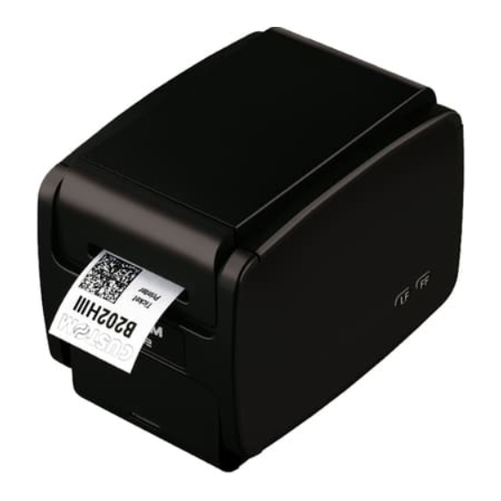
- Page 1 USER MANUAL KPM150HIII B202HIII...
- Page 3 CUSTOM S.p.A. GENERAL SAFETY INFORMATION THE CE MARK AFFIXED TO THE PRODUCT CERTIFY THAT THE Via Berettine 2/B Your attention is drawn to the following actions PRODUCT SATISFIES THE BA- that could compromise the characteristics of the 43010 Fontevivo (PARMA) - Italy SIC SAFETY REQUIREMENTS.
- Page 5 MANUAL For details on the commands, refer to the manual with code 77200000004600 For further information about the use of “PrinterSet” tool refer to the manual with code 78200000001800...
-
Page 7: Table Of Contents
TABLE OF CONTENTS 1 INTRODUCTION ............. . 9 2 IDENTIFICATION OF THE MODELS . - Page 8 7 ALIGNMENT ..............77 7.1 Enable alignment .
-
Page 9: Introduction
1 INTRODUCTION This document is divided into sections and chapters. Each chapter can be reached by the index at the beginning of this document. The index can be reached by the button on each page as shown in the diagram below. Link to table of contents Notes reference Numbered title... -
Page 11: Identification Of The Models
2 IDENTIFICATION OF THE MODELS NOMENCLATURE DESCRIPTION KPM150HIII base coniguration (OEM model with lateral connectors) KPM150HIII LAT KPM150HIII base coniguration (OEM model with rear connectors) KPM150HIII REAR B202HIII base coniguration (TKT model) B202HIII... -
Page 13: Description
Make sure that all the components illustrated below are present and that there are no signs of damage. If there are, contact Customer Service. KPM150HIII LAT, KPM150HIII REAR 1. Installation instruction sheet 2. Adapter cable for power supply 3. - Page 14 B202HIII 1. AC Power supply 2. Short guide 3. AC power cord 4. USB cable 5. Device...
-
Page 15: Device Components: External Views
3.2 Device components: external views KPM150HIII LAT 1. Device cover 5. Paper out 2. Device chassis 6. Product label 3. Keys and connector panel (see paragraph 3.3) 7. Paper input 4. Cutter unit 8. Lever of paper mouth guide (adjustable) - Page 16 KPM150HIII REAR 1. Device chassis 7. Paper out 2. Device cover 8. Product label 3. Printing head group 9. LINE FEED key 4. Paper input 10. FORM FEED key 5. Keys and connectors panel (see paragraph 3.3) 11. Status LED 6.
- Page 17 B202HIII 1. Device cover 6. Paper compartment cover 2. Paper output 7. Lever of paper mouth guide (adjustable) 3. Status LED 8. Keys and connector panel (see paragraph 3.3) 4. LINE FEED key 9. Paper input 5. FORM FEED key...
-
Page 18: Device Components: Keys And Connectors Panel
3.3 Device components: keys and connectors panel KPM150HIII LAT 1. USB port 2. Power supply port 3. LINE FEED key 4. SD/MMC (optional) 5. Connector for external low paper sensor 6. FORM FEED key 7. RS232 serial port 8. Status LED... - Page 19 KPM150HIII REAR 1. RS232 serial port 2. USB port 3. Power supply port 4. Connector for external low paper sensor...
- Page 20 B202HIII 1. Connector for external low paper sensor 2. RS232 serial port 3. USB port 4. Power supply port 5. ON/OFF key...
-
Page 21: Device Components: Internal Views
3.4 Device components: internal views KPM150HIII LAT 1. Paper presence sensors on output 2. Mobile sensor lower for black mark 3. Cover open sensor 4. Sensors of paper presence 5. Upper transparence sensor and black mark 6. Head temperature sensor NOTE: For ease of reference, for some models is represented only the internal printer group without the external plastic chassis. - Page 22 KPM150HIII REAR 1. Paper presence sensors on output 2. Mobile sensor lower for black mark 3. Cover open sensor 4. Sensors of paper presence 5. Upper transparence sensor and black mark 6. Head temperature sensor...
-
Page 23: Device Labels
3.5 Device labels PC = Product code (14 digits) SN = Serial number HW = Hardware release XXXXXXXXXXXXXX xxxxxx xxx xxxx xxxx xxxxxx xxx xxxx xxxx 0000000000000000000... -
Page 24: Key Functions: Power Up
3.6 Key functions: power up POWER UP Hold down Hold down Print Perform the SETUP report FONT TEST Fast push Fast push Fast push Skip the Enter the Enter the SETUP procedure Clock SETUP SETUP PROCEDURE Fast push Fast push Modify Next selected parameter... -
Page 25: Key Functions: Standby
3.7 Key functions: standby STANDBY Fast push Fast push Fast push Advance the paper Printing (preset length) logos “Black Mark Position” “Black Mark Position” “Notch/B.Mark Position” “Notch/B.Mark Position” parameter is set parameter is set parameter is set parameter is set on “Disabled”... -
Page 26: Status Messages
3.8 Status messages The status LED indicates hardware status of device. Given in the table below are the various LED signals and the cor- responding device status. KPM150HIII LAT, KPM150HIII REAR STATUS LED DESCRIPTION PRINTER OFF GREEN PRINTER ON: NO ERROR... - Page 27 B202HIII STATUS LED DESCRIPTION DEVICE OFF BLUE DEVICE ON: NO ERROR RECEIVE DATA RECEPTION ERRORS (PARITY, FRAME ERROR, OVERRUN ERROR) BLUE COMMUNICATION COMMAND NOT RECOGNIZED STATUS COMMAND RECEPTION TIME OUT LOW PAPER PRINTHEAD OVERHEATED PAPER END VIOLET PAPER JAM RECOVERABLE ERROR POWER SUPPLY VOLTAGE INCORRECT COVER OPEN...
-
Page 29: Installation
4 INSTALLATION 4.1 Fixing NOTE: All the dimensions shown in igures are in millimeters. KPM150HIII LAT The printer is provided with four ixing holes placed on lateral side (see following igure). To fasten the printer on a panel, use four M3 screws. - Page 30 KPM150HIII REAR The device is provided with four ixing holes placed on lateral side (see following igure). To fasten the printer on a panel, use four M4 screws. It’s very important to consider the screws length not to damage the internal components placed near the ixing holes (see following igure). Device chassis Fixing panel Section A-A Fixing screw The screw length (L) will be calculated according to the thickness of the panel (Sp) on which the device is ixed, as follows: L ≤ 10 mm + Sp For example, if panel thickness is 10 mm (Sp = 10 mm), the maximum length for screws will be 20 mm.
-
Page 31: Additional Low Paper Sensor
4.2 Additional low paper sensor KPM150HIII LAT, KPM150HIII REAR The device includes an additional low paper sensor with wiring cable (see following igure). To ix the sensor use an M3 screw not supplied. MATERIAL NOT MATERIAL INCLUDED INCLUDED Low paper sensor Fixing screw M3 Low paper wiring Connector Low paper sensor board 21.1 For the assembly procedure, proceed as follows:... - Page 32 KPM150HIII LAT Low paper wiring KPM150HIII REAR Low paper wiring Connect the wiring coming from the low paper sensor board at the connector shown in figure.
- Page 33 B202HIII The device not includes a low paper sensor kit. It is available as an accessory (see chapter 11) the low paper sensor board code 81300000000383 and the wiring cable code 26300000000519 (see following igure). To ix the sensor use an M3 screw not supplied. CODE CODE MATERIAL NOT 81300000000383 26300000000519 INCLUDED Low paper Low paper wiring Connector Fixing screw M3 sensor board...
- Page 34 Low paper wiring Connect the wiring coming from the low paper sensor board at the connector shown in figure...
-
Page 35: Connections
4.3 Connections The following igures show the possible connections for the devices. KPM150HIII LAT Serial Adapter cable standard cable standard cable for power supply (included, chapter USB device Power supply serial device ATTENTION: In some using conditions, we recommend the installation of a ferrite core on the power supply cable. - Page 36 KPM150HIII REAR Serial Adapter cable standard cable standard cable for power supply (included, chapter serial device USB device Power supply ATTENTION: In some using conditions, we recommend the installation of a ferrite core on the power supply cable. NOTE: When the RS232 and USB communication cables are connected to the printer at the same time, communica-...
- Page 37 B202HIII Power Suppy cable (included, chapter Serial standard cable standard cable Power supply USB device serial device NOTE: When the RS232 and USB communication cables are connected to the printer at the same time, communica- tion takes place via the USB port.
-
Page 38: Pinout
4.4 Pinout KPM150HIII LAT POWER SUPPLY Male Molex connector series 5566 vertical (no. 39-28-1023) 1 +24 Vdc 2 GND ATTENTION: Respect power supply polarity. NOTE: Power supply cable The following igure shows the connector pinout of the power supply cable for the device: Female Molex connector Power supply cable series 5557 (n° 39-01-3022) Cable... - Page 39 RS232 SERIAL INTERFACE Female DB9 connector 1 DTR When +VRS232, device is power on 2 TX During transmission, takes the values -VRS232 and + VRS232 depending on data 3 RX During reception, takes the values -VRS232 and +VRS232 depending on data 4 DSR 5 GND 6 DTR...
- Page 40 KPM150HIII REAR POWER SUPPLY Male Molex connector series 5566 vertical (no. 39-28-1023) 1 +24 Vdc 2 GND ATTENTION: Respect power supply polarity. NOTE: Power supply cable The following igure shows the connector pinout of the power supply cable for the device: Female Molex connector Power supply cable series 5557 (n° 39-01-3022) Cable Signal color...
- Page 41 RS232 SERIAL INTERFACE Female DB9 connector 1 DTR When +VRS232, device is power on 2 TX During transmission, takes the values -VRS232 and + VRS232 depending on data 3 RX During reception, takes the values -VRS232 and +VRS232 depending on data 4 DSR 5 GND 6 DTR...
- Page 42 B202HIII POWER SUPPLY Tripolar female connector 1 GND 2 +24 Vdc 3 GND 4 Frame GND ATTENTION: Respect power supply polarity. NOTE: Power supply cable The following igure shows the connector pinout of the power supply cable for the device: Tripolar male connector n.c. +24 V Power supply cable USB INTERFACE Female USB type B connector 1 VUSB (in) 2 D-...
- Page 43 RS232 SERIAL INTERFACE Female DB9 connector 1 DTR When +VRS232, device is power on 2 TX During transmission, takes the values -VRS232 and + VRS232 depending on data 3 RX During reception, takes the values -VRS232 and +VRS232 depending on data 4 DSR 5 GND 6 DTR...
-
Page 44: Driver And Sdk
4.5 Driver and SDK The drivers for the following operating system are available in the website www.custom4u.it: OPERATING SYSTEM DESCRIPTION INSTALLATION PROCEDURE Driver for Windows XP Driver for Windows VISTA (32/64bit) Driver for Windows 7 (32/64bit) From the START menu, press Run and type-in the path where the SW Driver for Windows 8 (32/64bit) Windows... -
Page 45: Operation
5 OPERATION 5.1 Opening device cover KPM150HIII LAT, KPM150HIII REAR B202HIII Push the opening lever in the direction shown in the figure. Open the upper plastic cover. Open the upper cover Open the paper compartment cover. of the device. -
Page 46: Adjusting Paper Width
5.2 Adjusting paper width Paper width may be adjusted from 20 mm to 54 mm using the lever of paper mouth guide located at the paper infeed open- ing as shown in the following igure. NOTE: For ease of reference, it is represented only the internal printer without the external plastic chassis. -
Page 47: Adjusting The Alignment Sensors
5.3 Adjusting the alignment sensors The device is equipped with a mobile sensor for the detection of the alignment black mark placed both on the non-thermal side of paper (located lower than the plane of the paper inside the device) as shown in the following igure. The device user will need to manually move this mobile sensor according to the position of the black mark on the paper (see chapter To use this sensor, you must set the “Black Mark Position”... - Page 48 In addition, the device is equipped with another sensor for black mark alignment placed on the thermal side of paper (lo- cated upper than the plane of the paper inside the device). This sensor is positioned on the upper lat under the print head and is ixed. To use this sensor for black mark detection, you must set the “Black Mark Position” setup parameter on the “Top” value (see chapter UPPER SENSOR FOR BLACK MARK...
- Page 49 To adjust the mobile sensor position according to the Black Mark Position on paper, irst adjust the paper width (see para- graph 5.2), then open the device cover (see paragraph 5.1) and move the sensor to the desired using a small screwdriver or a pointed object. ATTENTION: To avoid damaging the sensor, use the plastic tabs as foothold for the screwdriver to push the sensor in the desired position.
-
Page 50: Switch The Device On
5.4 Switch the device on KPM150HIII LAT Power supply (optional) Adapter for power supply (included) Connect the power adapter (included) The green LED turn on to an external power supply unit. and the device is ready. IN DC 24V 0.8A... - Page 51 KPM150HIII REAR Power supply (optional) Adapter for power supply (included) Connect the power adapter (included) The green LED turn on to an external power supply unit. and the device is ready. IN DC 24V 0.8A Adapter cable (included) Connect the power adapter cable to the device.
- Page 52 B202HIII IN DC 24V 1.0A Power cord (included) Power supply (included) Connect the power adapter (included) to the device and the mains outlet. Use the type of electrical power supply indicated on the label. ON/OFF Switch the device on pressing ON/OFF key. The bue LED turn on and the device is ready.
-
Page 53: Loading The Paper Roll
5.5 Loading the paper roll At every change of paper, check inside the device. To change the paper proceed as follows. KPM150HIII LAT, KPM150HIII REAR Push the opening lever Adjust the paper width (see paragraph 5.2) and black in the direction shown in the figure. - Page 54 Insert the paper into the input mouth so that it unrolls correctly. Be sure that the paper is correctly positioned into paper guides. ROOM Wait until the paper is automatically loaded.
- Page 55 B202HIII Open the paper compartment cover. Open the upper plastic cover. Adjust the position of the notch sensor according to the paper characteristics (be careful Adjust the paper width properly. not to damage the sensor).
- Page 56 thermal side Close the paper compartment cover. Insert the paper into the input mouth so that it unrolls correctly. Be sure that the paper is correctly positioned into paper guides. ROOM Close the Wait until the paper is upper plastic cover. automatically loaded.
- Page 57 The following igure gives the limit positions of the paper roll related to the printer for a correct paper loading without a paper roll holder support. The direction of the paper will always form a maximum angle of 90 ° or -90 ° with the insertion plane of paper inside the printer. 90° 90° -90° -90° NOTE: For ease of reference, in some igures is represented only the internal printer without the external plastic chassis.
-
Page 59: Configuration
6 CONFIGURATION 6.1 Coniguration by keys To enter the coniguration mode and print a setup report with the operating parameters of the device, proceed as follows. KPM150HIII LAT LF LINE FEED KEY Power supply cable (included) While pressing the LF LINE FEED key, switch on the device by connecting the powe supply cable (see paragraph 5.4). The device prints the report with the settings parameters. - Page 60 KPM150HIII REAR Power supply cable (included) LF LINE FEED KEY While pressing the LF LINE FEED key, switch on the device by connecting the powe supply cable (see paragraph 5.4). The device prints the report with the settings parameters. Follow the instruction printed on the paper to proceed with configuration procedure.
- Page 61 B202HIII LF LINE FEED KEY ON/OFF While pressing the LF LINE FEED key, switch on the device by pressing the ON/OFF key (see paragraph 5.4). The device prints the report with the settings parameters. Follow the instruction printed on the paper to proceed with configuration procedure.
- Page 62 The following igure shows the device setup report. The shown values for parameters are sample values; for a detailed description of the device operating parameters see the following paragraphs. <device name> DEVICE NAME, FIRMWARE MODULES SCODE: <code> rel 1.00 FCODE: <code> rel 1.00 RELEASE and DCODE: <code> rel 1.00 SERIAL NUMBER S/N: <number> PRINTER SETTINGS 1 • • • • • • • • 448 PRINTHEAD --------------------------------------------------------------------------- STATUS...
-
Page 63: Coniguration By Software
6.2 Coniguration by software The setup parameters can be set by using the “PrinterSet” software tool available on www.custom4u.it. For a detailed description of the device operating parameters see the following paragraphs. To conigure the device by software, proceed as follows: PORT LOAD SAVE SETUP FONTS UPGRADE Connect the device to a PC directly Connect the device to a PC directly Click on SETUP to access the operating parameteres of (see... -
Page 64: Coniguration By Ile
6.3 Coniguration by ile The setup parameters can be set by editing the “Setup.ini” ile stored on the Flash Drive of the device. Proceed as follows: Enter setup Enter the coniguration procedure by keys (see paragraph 6.1) or by software (see paragraph 6.2). Plug the device to a Personal Computer via USB. <parameter> ......: <value> <parameter> ......: <value> <parameter> ......: <value> <parameter>... - Page 65 The “Setup.ini” ile is a coniguration ile that contains all the conigurable parameters listed in text format and divided into some sections (indicated between square brackets). For each parameter, you ind the parameter name followed by the value currently set and then the available values listed with a reference number. The reference number marked with the symbol ‘ * ’ is the default one (see igure). Value set Section [PRINT] Parameter name Speed / Quality = 2 0 = High Quality 1 = Normal // * 2 = High Speed Availables values Default marker...
-
Page 66: Printhead Status
6.4 Printhead status The device performs the printhead operating status when printing the setup report. The total number of dots is reported Are indicated the total dots number of the printhead and their status (see igure below). DCODE: <code> rel 1.00 S/N: <number> Total no. printhead dots PRINTER SETTINGS 1 • • • • • • • • 448 ------------------------------------------------------------------------ PRINTHEAD WORKING GOOD! Printhead status,... -
Page 67: Device Status
6.5 Device status The device operating status is indicated in the coniguration print-out in which, next to the name of the components dis- played, the following information is given: device model PRINTER TYPE RFID module presence of RFID module RFID module irmware release RFID MODULE RELEASE * Barcode Reader presence of the barcode reader INTERFACE interface present OK appears if functioning and NOT OK if faulty PROGRAM MEMORY TEST DYNAMIC RAM TEST OK appears if functioning and NOT OK if faulty... -
Page 68: Communication Parameters
6.6 Communication parameters These devices allow the coniguration of the parameters listed in the following table. The parameters marked with the symbol are the default values. Settings remain active even after the device has been turned off and they are stored in non-volatile memory. RS232 BAUD RATE Communication speed of the serial interface: 115200 38400 9600... - Page 69 USB communication class deinition. USB CLASS Printer setting the printer function Mass Storage = setting the sharing mode from Mass Storage Virtual COM = setting the USB port as a virtual serial port NOTE: To use the “Virtual COM” value, it is necessary to install an additional driver (see paragraph 4.5).
-
Page 70: Operation Parameters
6.7 Operation parameters These devices allow the coniguration of the parameters listed in the following table. The parameters marked with the symbol are the default values. Settings remain active even after the device has been turned off and they are stored in non-volatile memory. PRINTER EMULATION Available emulations for the device: CUSTOM/POS SVELTA AUTOLOAD NO RECOVERY This parameter, if enabled, does not perform the paper recovery mode after autoload. - Page 71 Setting the low paper sensor: LOW PAPER Disabled = Sensor disabled Enabled = Sensor enabled TICKET MANAGEMENT This parameter allows the ticket management: Disabled = no check Short Ticket = it is possible to manage tickets with length less than the distance between the black mark sensor and the printing line PAPEREND BUFFER Cleaning mode of the data in receive buffer, if the printing is stopped due to lack of paper:...
- Page 72 Adjusting the printing density: PRINT DENSITY -25% -12% +12% +25% Printing mode: PRINT MODE Normal = enables printing in normal writing way Reverse = enables printing rotated 180 degrees SPEED / QUALITY Setting of printing speed and printing quality: Normal High Quality High Speed PAPER THRESHOLD...
-
Page 73: Alignment Parameters
6.8 Alignment parameters These devices allow the coniguration of the parameters listed in the following table. The parameters marked with the symbol are the default values. Settings remain active even after the device has been turned off and they are stored in non-volatile memory. BLACK MARK Position of the black mark alignment and choice of appropriate black mark sensor: POSITION Disabled the black mark alignment is not performed... - Page 74 NOTES: For example, to set a positive black mark distance value of 15mm, modify the param- eters as follows: Black Mark Distance Sign = + Black Mark Distance [mm x 10] Black Mark Distance [mm x 1] Black Mark Distance [mm x .1] If the “Black Mark Position”...
-
Page 75: Hexadecimal Dump
6.9 Hexadecimal dump This function is used for the diagnosis of the characters received from the communications port. Characters are printed as hexadecimal code and the corresponding ASCII code (see below). Each line is preceded by a counter in hexadecimal that indicates the number of bytes received. -
Page 76: Calendar Clock
6.10 Calendar clock The devices are equipped with a Real Time Clock. During power-up, held down the LF LINE FEED key to enter in the printer coniguration mode. Pressing both the LF and FF keys to enter in the clock coniguration (see following igure). Press the LF LINE FEED key to modify date/time; the device will print the updated date and time. Follow the instructions printed on the paper for the key functionality. The highlighted digit (the number is written in negative mode) indicates the digit to be modiied. Press the LF LINE FEED key to modify the value of the highlighted digit; every ... -
Page 77: Alignment
7 ALIGNMENT Device is provided with sensors for the use of alignment black mark in order to handle: roll of tickets with pre-printed ields and a ixed length; • Fan-fold module of tickets with pre-printed ields and a ixed length. • The black mark alignment may be formed by (see paragraph 9.10): black mark printed on paper; • hole between two tickets; • • gap between two labels. All alignment sensors are “relection” sensors: this kind of sensor emits a band of light and detects the quantity of light ... -
Page 78: Enable Alignment
7.1 Enable alignment Device is provided with two sensors for alignment, placed as follows: one mobile sensor on the lower lat • one sensor on the upper lat. • To guarantee the alignment, it is necessary to correctly choose the sensor to use for the black mark detection depending on the type of black mark and its location on the ticket. To do this, you must enable the parameter “Black Mark Position”... - Page 79 Paper with black mark on the non-thermal side direction paper feed NON-TERMAL SENSOR 1 SIDE...
- Page 80 Paper with black mark on the thermal side direction paper feed SENSOR 2 THERMAL SIDE...
- Page 81 Tickets with hole SENSOR 2 direction paper feed SENSOR 1...
- Page 82 Paper with labels SENSOR 2 direction paper feed SENSOR 1...
-
Page 83: Calibration
7.2 Calibration The sensor calibration occurs automatically and consists in adjusting the quantity of light emitted to match the degree of whiteness of the paper used and the degree of black of the mark printed on paper. The device automatically performs the self-calibration during the setup procedure only if the “Black Mark Position” parameter is set to a value other than “Disabled”... - Page 84 The following igure shows an example of paper with holes: the outgoing voltage is constant while passing the paper be- tween two holes and presents a variation at each hole. In this case, the optimal value for the “Black mark threshold” parameter is placed about half of the variation. NON-THERMAL SIDE “Black mark threshold” Peak THERMAL SIDE...
- Page 85 The following igure shows an example of paper with the non-thermal paper printed with black marks and other graphics (for example, a barcode): the outgoing voltage is constant while passing the white paper between two black marks, presents a peak at each black mark and presents some “noise” at each barcode. In this case, the optimal value for the “Black mark threshold” parameter is located about halfway between the peak value and the maximum value of the “noise” (as shown in igure): NON-THERMAL SIDE Peak...
-
Page 86: Alignment Parameters
7.3 Alignment parameters The “alignment point” is deined as the position inside the ticket to use for the black mark alignment. If you use paper with perforation (Fan-fold modules), the alignment point corresponds with the edge of the ticket. The distance between the black mark edge and the alignment point is deined as “Black Mark Distance”. Referring to the front of the black mark, the value of “Black Mark Distance” can be positive or negative. If the “Black Mark Distance” value is set to 0, the alignment point is set at the beginning of the black mark: Alignment Alignment point:... - Page 87 To set a negative value of the “Black Mark Distance” parameter is useful in cases where the alignment point refers to the black mark printed on the previous ticket or where the desired tear-off line is placed in the middle of the black mark align- ment (for example, for paper with holes or gap).
- Page 88 The following igure shows a simpliied section of the device with the paper path and the distance (expressed in millimeters) between the alignment sensor, the printing head and the autocutter (cutting line). A = 26.5mm = distance between the cutting line (autocutter) and the printing line (printhead) on paper B = 39.7mm = distance between the the printing line (printhead) and the alignment sensor...
- Page 89 CUSTOM/POS emulation To deine the alignment point you need to set the printer parameters that compose the numerical value of the “Black Mark Distance” parameter (see paragraph 6.8). For example, to set a black mark distance of 15 mm between the black mark and the alignment point, the parameters must be set on the following values: Black Mark Distance Sign Black Mark Distance [mm x 10] Black Mark Distance [mm x 1] Black Mark Distance [mm x .1]...
-
Page 90: Printing Area
7.4 Printing area In order to print ticket containing only one black mark and to not overlay printing to a black mark (that will make it useless for the next alignment), it is important to well calibrate the length of the printing area of ticket according to the inter-black mark distance. -
Page 91: Maintenance
8 MAINTENANCE 8.1 Printer paper jam Open the upper cover of the device (see paragraph 5.1). Close the upper cover of the device. ROOM Insert the paper (see paragraph 5.5). NOTE: For ease of reference, in some igures is rep- Remove the damaged paper and check the presence resented only the internal printer without the external for paper scraps inside the device. -
Page 92: Planning Of Cleaning Operations
8.2 Planning of cleaning operations The regular cleaning of the device keeps the print quality and extends its life. The following table shows the recommended planning for the cleaning operations. EVERY PAPER CHANGE Printing head Use isopropyl alcohol Printing roll Use isopropyl alcohol EVERY 5 PAPER CHANGES Paper path... -
Page 93: Cleaning
8.3 Cleaning For periodic cleaning of the device, see the instructions below Case Sensors Disconnect the power supply cable and open the upper Disconnect the power supply cable. device cover (see paragraph 5.1). ATTENTION: ATTENTION: Do not use alcohol, solvents, or hard brushes. Do not use alcohol, solvents, or hard brushes. - Page 94 Printing head Printing roller Disconnect the power supply cable and open the upper Disconnect the power supply cable and open the upper device cover (see paragraph 5.1). device cover (see paragraph 5.1). ISOPROPYL ALCOHOL ISOPROPYL ALCOHOL ATTENTION: ATTENTION: Do not use alcohol, solvents, or hard brushes. Do not use alcohol, solvents, or hard brushes.
- Page 95 Paper path Cutter Disconnect the power supply cable and open the upper Disconnect the power supply cable and open the upper device cover (see paragraph 5.1). device cover (see paragraph 5.1). ATTENZIONE: ATTENZIONE: Non utilizzare solventi o spazzole dure. Assicurarsi che Non utilizzare solventi o spazzole dure.
-
Page 96: Upgrade Irmware
8.4 Upgrade irmware Firmware upgrade can be performed by using the “PrinterSet” software tool available on www.custom4u.it. To upgrade irmware, proceed as follows: PORT LOAD SAVE From Device From File Login to the website www.custom4u.it, type in the Accedere al sito www.custom4u.it, eseguire il login, product code of the device and download the latest digitare il codice prodotto del proprio dispositivo irmware release available. -
Page 97: Specification
9 SPECIFICATION 9.1 Hardware speciications GENERAL Head temperature, ticket presence, black mark detector in 3 positions, Sensors translucent gap/hole detector (setting by software), ticket presence on output, cover open, external low paper. Noise B202HIII 66.3 dB Emulations CUSTOM/POS, SVELTA Windows XP, VISTA (32/64bit), Windows 7 (32/64bit) Windows 8 (32/64 bit),... - Page 98 CODABAR, CODE93, CODE128, CODE32, PDF417, DATAMATRIX, AZTEC, QRCODE Printing speed (2) (6) High quality = 80 mm/s KPM150HIII LAT, KPM150HIII REAR Normal = 120 mm/s High speed = 180 mm/s High quality = 80 mm/s B202HIII Normal = 117 mm/s...
- Page 99 50 Hz to 60 Hz Output 24 V, 2.5 A Power 60 W ENVIRONMENTAL CONDITIONS Operating temperature KPM150HIII LAT, KPM150HIII REAR from -10 to +60 °C B202HIII from 0°C to +50°C Relative humidity from 10% Rh to 85% Rh (w/o condensation)
- Page 100 Storage temperature from -20 °C to +70 °C Storage relative humidity from 10% Rh to 90% Rh (w/o condensation) NOTES: (1) : Only for printer models equipped with SD/MMC. (2) : Respecting the regular schedule of cleaning for the device components. (3) : Damages caused by scratches, ESD and electromigration are excluded.
-
Page 101: Character Speciications
9.2 Character speciications Character set Character density 11 cpi 15 cpi 20 cpi Number of columns Chars / sec 2900 3800 5300 Lines / sec Characters (L x H mm)-Normal 2.25 x 3 1.75 x 3 1.25 x 3 NOTE: Theoretical values. 9.3 Speciications for RFID reader/writer (optional) TRANSPONDER SPECIFICATIONS for models with UHF RFID reader/writer (UHF CUSTOM) Supported transponders... -
Page 102: Device Dimensions
9.4 Device dimensions KPM150HIII LAT Length 171 mm Width 114 mm Height 122 mm Weight 1850 g NOTE: All the dimensions shown in the following igure are in millimeters and referred to devices with covers closed and without paper rolls. 99.5 175.5... - Page 103 KPM150HIII REAR Length 184.5 mm Width 96 mm Height 122 mm Weight 1850 g NOTE: All the dimensions shown in the following igure are in millimeters and referred to devices with covers closed and without paper rolls. 184.5...
- Page 104 B202HIII, Length 194 mm Width 133 mm Height 155 mm Weight 2800 g NOTE: All the dimensions shown in the following igure are in millimeters and referred to devices with covers closed and without paper rolls. 133.2...
-
Page 105: Device Dimensions With Stop Device Ticket Kit
9.5 Device dimensions with stop device ticket kit code 970AN010000001 (optional) KPM150HIII LAT, KPM150HIII REAR Length 194 mm Height 122 mm Width 114 mm Weight 1900 g 99.5 175.5 NOTE: All the dimensions shown in igure are in millimeters and referred to devices with covers closed and without paper rolls. - Page 106 KPM150HIII REAR Length 194 mm Height 122 mm Width 114 mm Weight 1900 g 207.5 184.5 N°4 M4 Mounting holes NOTE: All the dimensions shown in igure are in millimeters and referred to devices with covers closed and without paper rolls.
-
Page 107: Device Dimensions With Ejecter / Retention Ticket Plastic Kit
9.6 Device dimensions with ejecter / retention ticket plastic kit code 976FB030000001 (optional) KPM150HIII LAT Length 194 mm Height 122 mm Width 114 mm Weight 1950 g 99.5 198.5 175.5 120 Fixing point NOTE: All the dimensions shown in igure are in millimeters and referred to devices with covers closed and without paper rolls. - Page 108 KPM150HIII REAR Length 194 mm Height 122 mm Width 114 mm Weight 1950 g 207.5 184.5 N°4 M4 Mounting holes NOTE: All the dimensions shown in igure are in millimeters and referred to devices with covers closed and without paper rolls.
-
Page 109: Device Dimensions With Paper Roll Holder
9.7 Device dimensions with paper roll holder code 974AP010000304 (optional) B202HIII, B202HIII UHF Length 364 mm Height 155 mm Width 133.2 mm Weight 3800 g 133.2 NOTE: All the dimensions shown in the igure are in millimeters and referred to devices with covers closed and without paper rolls. -
Page 110: Device Dimensions With Metallic Ticket Tray
9.8 Device dimensions with metallic ticket tray code 97000000000200 (optional) B202HIII Length 363.5 mm Height 155 mm Width 133.2 mm Weight 3000 g 363.5 NOTE: All the dimensions shown in the igure are in millimeters and referred to devices with covers closed and without paper rolls. -
Page 111: Dimensions Of Power Supply, Power Cord And Adapter Cable
35.5 mm Width 56 mm POWER CORD code 26100000000311 (only for B202HIII, B202HIII UHF models) Length 2000 mm ADAPTER CABLE code 26900000000005 (only for KPM150HIII LAT, KPM150HIII REAR models) Length 200 mm POWER SUPPLY code 963GE020000053 AC INLET n.c. +24V DC OUTPUT WIRE NOTE: All the dimensions shown in igures are in millimeters. - Page 112 POWER CORD code 26100000000311 2000 ADAPTER CABLE code 26900000000005 NOTE: All the dimensions shown in igures are in millimeters.
-
Page 113: Paper Speciication
9.10 Paper speciication Paper with black mark on the non-thermal side The following image shows the placement of the black mark on the non-thermal side of the paper. The black mark can be positioned anywhere on the whole width of the paper, because the black mark detector is a mobile sensor. For more information about the use of paper with black mark see chapter NOTE: All the dimensions shown in following igures are in millimeters. - Page 114 Paper with black mark on the thermal side The following image shows the placement of the black mark on the thermal side of the paper. This sample paper is for the printer models with the upper black mark detector. For more information about the use of paper with black mark see chapter NOTE: All the dimensions shown in following igures are in millimeters.
- Page 115 Paper with labels The following image shows a portion of paper with labels. To manage paper with label, you need to set the parameter “Ticket Management” to “Short Label” value (see chapter 6). For more information about the use of paper with labels see chapter max 2 mm Edge used for...
- Page 116 Fan-fold paper with hole The following image shows the placement of the hole on the paper. To manage tickets with hole, set the parameter “Black Mark Position” to “Transparent” (see chapter 6). For more information about the use of paper with hole see chapter NOTE: The valid format of the ticket is ISO size 54 x 85mm.
- Page 117 Ticket with RFID tag (only with optional RFID reader/writer) RFID (acronym for Radio Frequency IDentiication) is a technology to identify automatically items using radio waves; this system is based on wireless data capture from RFID tag using appropriate readers. The RFID tag, or transponder, is made up of : the microchip that stores the data (including also a unique serial number written); • • an RFID antenna. The models with RFID reader/writer are equipped with an RFID transceiver, provided with antenna, that allows to send and receive RF data to and from the tag.
-
Page 118: Character Sets In Custom/Pos Emulation
9.11 Character sets in CUSTOM/POS emulation The device has 4 fonts of varying width (11, 15, 20 and 25 cpi) which may be related one of the coding tables provided on the device. To know the coding tables actually present on the device, you need to print the font test (see paragraph 3.6). - Page 119 <CodeTable> Coding table WPC775 - Baltic Rim on request PC855 - Cyrillic PC861 - Icelandic on request PC862 - Hebrew PC864 - Arabic PC869 - Greek on request ISO8859-2 - Latin 2 on request ISO8859-15 - Latin 9 on request PC1098 - Farci PC1118 - Lithuanian on request...
-
Page 120: Character Sets In Svelta Emulation
9.12 Character sets in SVELTA emulation In SVELTA emulation, the device has 20 embedded fonts of varying width which may be accessed through control charac- ters (see the Commands Manual of the device). The following list shows the font available and relative dimensions in dot: ... -
Page 121: Consumables
10 CONSUMABLES The following table shows the list of available consumables for device: DESCRIPTION CODE 67300000000340 THERMAL PAPER ROLL weight = 145 g/m width = 54 mm Ø external = 300 mm Ø core = 76 mm 67300000000342 THERMAL PAPER ROLL weight = 74 g/m width = 54 mm Ø... -
Page 123: Accessories
11 ACCESSORIES The following table shows the list of available accessories for device. KPM150HIII LAT, KPM150HIII REAR DESCRIPTION CODE 963GE020000053 POWER SUPPLY (for technical speciications, see paragraph 9.1) 26900000000005 ADAPTER CABLE FOR POWER SUPPLY length = 200 mm (see paragraph 9.9) 970AN010000001 STOP DEVICE TICKET KIT (for technical speciications, see paragraph... - Page 124 B202HIII DESCRIPTION CODE 963GE020000053 POWER SUPPLY (for technical speciications, see paragraph 9.1) 26100000000311 POWER CORD SCHUKO PLUG length = 2 m (see paragraph 9.9) 974AP010000304 PAPER ROLL HOLDER (for technical speciications, see paragraph 9.7) 97000000000200 FANFOLD HOLDER (for technical speciications, see paragraph 9.8) 21100000001060 BRACKET PRINTER 26300000000519 ADDITIONAL CABLE FOR LOW PAPER SENSOR cable 400 mm long...
- Page 125 81300000000383 ADDITIONAL LOW PAPER SENSOR BOARD...
-
Page 126: Adapter Cable For Power Supply
For the device is available an adapter cable (code 26900000000005) supplied as an accessory, for connecting the device to the external power supply unit (code 963GE020000053 - optional). KPM150HIII LAT Assembly instructions Connect the adapter cable to the power supply unit as follows:... - Page 127 KPM150HIII REAR Assembly instructions Connect the adapter cable to the power supply unit as follows:...
-
Page 129: Technical Service
12 TECHNICAL SERVICE In case of failure, contact the technical service accessing the website www.custom4u.it and using the support tools on the homepage. It is advisable to keep the identiication data of the product at hand. The product code, the serial number and the hardware release number can be found on the product label (see paragraph 3.5). - Page 132 CUSTOM S.p.A. World Headquarters Via Berettine, 2/B - 43010 Fontevivo, Parma ITALY Tel. +39 0521 680111 - Fax +39 0521 610701 info@custom.biz - www.custom.biz All rights reserved www.custom.biz...
Need help?
Do you have a question about the KPM150HIII and is the answer not in the manual?
Questions and answers