Table of Contents
Advertisement
Advertisement
Table of Contents

Related Manuals for Custom Audio Electronics KPM216HII-ETH


Summary of Contents for Custom Audio Electronics KPM216HII-ETH
- Page 1 USER MANUAL KPM216HII ETH KPM216HII ETH 77200000000900 Commands manual:...
- Page 2 CUSTOM S.p.A. GENERAL SAFETY INFORMATION THE CE MARK AFFIXED TO Your attention is drawn to the following THE PRODUCT CERTIFY Via Berettine 2/B actions that could compromise the char- THAT THE PRODUCT SAT- 43010 Fontevivo (PARMA) - Italy acteristics of the product: ISFIES THE BASIC SAFETY Tel.
-
Page 3: Table Of Contents
TABLE OF CONTENTS INDEX 1 INTRODUCTION ..............................5 Document structure ............................5 Explanatory notes used in this manual ......................5 2 DESCRIPTION ............................... 7 Unpacking the device ........................... 7 Device components ............................8 Device components: connectors view ......................10 Key functions .............................. 11 Status led fl... - Page 4 TABLE OF CONTENTS Character sets in SVELTA emulation ......................80 8 CONSUMABLES ..............................81 9 ACCESSORIES ..............................83 Kit for near paper end ..........................84 10 ALIGNMENT ................................ 85 10.1 Enable alignment ............................85 10.2 Calibration ..............................85 10.3 Alignment parameters ..........................87 10.4 Printing area ...............................
-
Page 5: Introduction
1. INTRODUCTION INTRODUCTION 1.1 Document structure This document includes the following chapters: 1 INTRODUCTION information about this document 2 DESCRIPTION general description of device 3 INSTALLATION information required for a correct installation of the device 4 OPERATION information required to make the device operative 5 CONFIGURATION description of the confi... - Page 6 1. INTRODUCTION 6 KPM216HII ETH User manual...
-
Page 7: Description
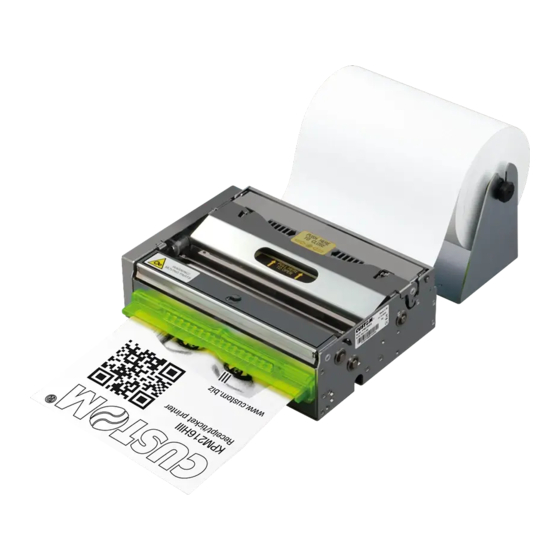
2. DESCRIPTION DESCRIPTION 2.1 Unpacking the device Remove the printer from its carton being careful not to damage the packing material so that it may be re-used if the printer is to be transported in the future. Make sure that all the components illustrated below are present and that there are no signs of damage. If there are, contact Customer Service. -
Page 8: Device Components
2. DESCRIPTION 2.2 Device components External view 1. Motorization cover 2. Lock/Unlock button of mo- torization cover 3. Printing head set 4. Opening lever of head set 5. Roller cover 6. Paper out, horizontal position (a) or vertical position (b) 7. - Page 9 2. DESCRIPTION Internal view 1. ‘Paper in presence’ sensor 2. Printing head 3. ‘Printing head open’ sensor 4. ‘Paper under the cutter’ sensor 5. Cutter 6. ‘Paper out presence’ sensor 7. Sensor for notch detection KPM216HII ETH 9 User manual...
-
Page 10: Device Components: Connectors View
2. DESCRIPTION 2.3 Device components: connectors view 1. SD/MMC card 2. USB connector 3. ETHERNET connector 4. RS232 connector 5. Power Supply connector 10 KPM216HII ETH User manual... -
Page 11: Key Functions
2. DESCRIPTION 2.4 Key functions The following fi gures show the functions of printer’s keys according to the operating condition of the device. POWER UP Hold down Hold down printing printing SETUP report FONT TEST Fast push Fast push Fast push skip the enter the SETUP MODE print the SETUP report... - Page 12 2. DESCRIPTION STANDBY Reset Fast push Fast push Advance the paper hardware reset (preset length) (power off/ power on) Is the “Notch Alignment” parameter set on “Disabled”? (see Setup) printing perform the demo ticket ticket alignment 12 KPM216HII ETH User manual...
-
Page 13: Status Led Fl Ashes
2. DESCRIPTION 2.5 Status led fl ashes The Status led indicates hardware status of device. Given in the table below are the various led signals and the cor- responding printer status. STATUS LED DESCRIPTION PRINTER OFF GREEN PRINTER ON: NO ERROR RECEIVE DATA RECEPTION ERRORS (PARITY, FRAME ERROR, OVERRUN ERROR) GREEN... - Page 14 2. DESCRIPTION 14 KPM216HII ETH User manual...
-
Page 15: Installation
3. INSTALLATION INSTALLATION 3.1 Mounting specifi cations The printer is designed for the following positions: +90° +90° WARNING Respect the mounting specifications to guar- antee the right ticket 45° 45° emission. Disable the parameter ‘Automatic ejecting’ (see par.5.4) Horizontal paper out model: •... -
Page 16: Fastening (Horizontal Paper Out Only)
3. INSTALLATION 3.2 Fastening (horizontal paper out only) The printer is provided with three fi xing holes on the bottom of device (see following fi gure). To fasten the printer on a panel, use three M4 screws It’s very important to consider the screws length to not damage the internal components placed near the fi xing holes (see following fi... -
Page 17: Fixing Brackets
3. INSTALLATION 3.3 Fixing brackets The printer includes a kit for the assembly of two additional fi xing brackets (see following fi gure). The kit contains: 1. Two fi xing brackets; 2. No.4 fi xing screws. For the assembly procedure, proceed as follows: BUTTON IN LOCKED POSITION... - Page 18 3. INSTALLATION Fix the brackets as shown in Fig. Observe the orientation of the slot A. The following fi gure shows the printer overall dimensions with the two additional brackets (dimensions in mm). 18 KPM216HII ETH User manual...
-
Page 19: Near Paper End Sensor
3. INSTALLATION 3.4 Near paper end sensor The printer includes a near paper end sensor with wiring (see following fi gure). To fi x the sensor use two M3 screws not supplied. MATERIAL NOT MATERIAL INCLUDED INCLUDED NPE sensor NPE wiring Fixing screws M3 sensor board... - Page 20 3. INSTALLATION NPE wiring Connect the wiring coming from the near paper end sensor board at the connector shown in figure 20 KPM216HII ETH User manual...
-
Page 21: Connections For Ethernet Model
3. INSTALLATION 3.5 Connections for Ethernet model The following fi gure shows the possible connections for device. RS232 POWER SUPPLY ATTENTION: In some using conditions, we recommend the installation of a ferrite core on the power supply cable. KPM216HII ETH 21 User manual... -
Page 22: Pinout
3. INSTALLATION 3.6 Pinout POWER SUPPLY Male Molex connector vertical (no. 39-30-0060) 1 +24 Vdc 2 +24 Vdc 3 +24 Vdc 4 GND 5 GND 6 GND ATTENTION: Respect power supply polarity. Nota: Power supply cable The following fi gure shows the connector pinout of the power supply cable for the device: Female connector Molex (n.39-01-2065) Cable color... -
Page 23: Rs232 Serial Interface
3. INSTALLATION RS232 SERIAL INTERFACE Female DB9 connector 1 DTR 2 TX During transmission, takes the values “0” and “1” depending on data. 3 RX During reception, takes the values “0” and “1” depending on data. 4 n.c. 5 GND 6 DTR When “1”, printer is power on. -
Page 24: Ethernet Interface
3. INSTALLATION ETHERNET INTERFACE Female RJ45 connector 1 TPOUT + 2 TPOUT - 3 TPIN + 4 GND 5 GND 6 TPIN - 7 n.c 8 n.c 9 +3.3 V 10 LED-LAN 11 +3.3 V 12 LED-LNK 13 Shield 14 Shield Note: The functionality of two led are specifi... -
Page 25: Driver
3. INSTALLATION 3.7 Driver The drivers are available for the following operating system: OPERATING DRIVER INSTALLATION PROCEDURE SYSTEM Windows XP From the START menu, press Enter and key-in the path where the SW was saved on your PC, Windows Windows VISTA (32/64bit) then click OK. - Page 26 3. INSTALLATION 26 KPM216HII ETH User manual...
-
Page 27: Operation
4. OPERATION OPERATION 4.1 Adjusting paper width Paper width may be adjusted from 194mm to 216mm by moving the mobile paper guides as shown in the following fi gure. KPM216HII ETH 27 User manual... -
Page 28: Turning On The Device
4. OPERATION 4.2 Turning on the device Status Reset Power Supply cable (supplied) The green led turns on EXTERNAL and the printer is ready. POWER SUPPLY UNIT (OPTIONAL) Connect the power supply cable (supplied) to an external power supply unit (optional). Power Supply cable (supplied) Connect the power supply cable... -
Page 29: Paper Insertion
4. OPERATION 4.3 Paper insertion Each time you change the paper, check inside the printer. To change the paper proceed as follows: Adjust the paper width (see previous paragraphs). ATTENTION: Make sure the cut is straight. Place the paper roll, so that it unrolls in the direction shown in figure. KPM216HII ETH 29 User manual... - Page 30 4. OPERATION Paper out in horizontal position ROOM Paper out in vertical position Insert the paper into the paper infeed opening and wait for it to load automatically. max 1° max 1° The following fi gure gives the limit positions of the paper roll related to the printer for a correct paper loading without a paper roll holder support.
-
Page 31: Issuing Ticket
4. OPERATION 4.4 Issuing ticket The printer allows you to choose between different operating modes for the issuance of printed tickets. The operating modes shown in the following images, depend on the settings of the confi guration parameters and commands sent to the printer. NOTE: For further information, refer to Chapter 5 and to the Commands Manual. - Page 32 4. OPERATION Paper out Ticket Paper cut Ejector rollers in horizontal position presented Paper out in vertical position Ticket presented When printing ends, the device cuts the ticket and presents a portion of the ticket printed on the paper mouth Paper out Ticket in horizontal position...
- Page 33 4. OPERATION “EJECT” MODE Paper input Printing head The device starts the ticket printing Paper input Printing head Ejector rollers Paper caught between rollers The ticket advances ahead to the ejector and is caught between the ejector rollers. The printed part of ticket is collected while the device continues printing KPM216HII ETH 33 User manual...
- Page 34 4. OPERATION Paper out Ticket in horizontal position presented Paper cut Ejector rollers Paper out in vertical position Ticket presented When printing ends, the device cuts the ticket and presents a portion of the ticket printed on the paper mouth The ticket is waiting on the paper mouth for a preset period of time Paper out Ticket...
- Page 35 4. OPERATION “RETRACT” MODE Paper input Printing head The device starts the ticket printing Paper input Printing head Ejector rollers Paper caught between rollers The ticket advances ahead to the ejector and is caught between the ejector rollers. The printed part of ticket is collected while the device continues printing KPM216HII ETH 35 User manual...
- Page 36 4. OPERATION Paper out Ticket in horizontal position presented Paper cut Ejector rollers Paper out in vertical position Ticket presented When printing ends, the device cuts the ticket and presents a portion of the ticket printed on the paper mouth The ticket is waiting on the paper mouth for a preset period of time Ticket Ejector...
-
Page 37: Memory Card Insertion
4. OPERATION 4.5 Memory card insertion To insert the memory card into the slot, proceed as follows: Lift up the print head using the Disconnect the opening slot (A) located on the cover power supply cable. BUTTON IN BUTTON IN LOCKED POSITION UNLOCKED POSITION ATTENTION:... - Page 38 4. OPERATION CONTACTS Insert the memory card into the slot, taking the contacts facing up. 38 KPM216HII ETH User manual...
-
Page 39: Configuration
5. CONFIGURATION CONFIGURATION 5.1 Confi guration mode To enter the confi guration mode and print a SETUP report with the operating parameters of the printer, proceed as follows. LINE FEED + POWER SUPPLY During power-up, hold down the LINE FEED key while the wiring is plugged into the power supply connector of the printer. - Page 40 5. CONFIGURATION LINE FEED FORM FEED DHCP Client ...... : Disabled FTP Server ......: Enabled IP Address ......2.168 Subnet Ma sk . sk ........ 55.25 D ef Defau ault G atewa way..
-
Page 41: Setup Report
5. CONFIGURATION 5.2 Setup report The following fi gures show the setup reports of the printer. The shown values for parameters are sample values; for the list and the description of printer and Ethernet parameters see the following paragraphs. KPM216HII printer SCODE: <code>... -
Page 42: Printer Status
5. CONFIGURATION [LF] enter Printer Setup KEYS FUNCTIONS [FF] enter Ethernet Setup (see paragraph 2.4) [LF + FF] skip Setup DHCP Client ......... : Disabled FTP Server ........: Disabled ETHERNET PARAMETERS IP Address ........: 192.168. 0. (see paragraph 5.5) Subnet Mask ........ -
Page 43: Printer Parameters
5. CONFIGURATION 5.4 Printer parameters This printer allows the confi guration of the parameters listed in the following table. The parameters marked with the symbol are the default values. Settings remain active even after the printer has been turned off and they are stored in non-volatile memory. Available emulations for the device: PRINTER EMULATION SVELTA... - Page 44 5. CONFIGURATION Printing mode: PRINT MODE Normal = enables printing in normal writing way Reverse = enables printing rotated 180 degrees Setting of the Carriage Return character: AUTOFEED CR disabled = Carriage Return disabled CR enabled = Carriage Return enabled NOTE: The parameter is printed only with ESC/POS emulation enabled.
- Page 45 5. CONFIGURATION Threshold value (in percent) for the recognition of the presence of paper by the paper PAPER THRESHOLD presence sensor: Management of the alignment notch NOTCH ALIGNMENT Disabled the notch alignment is not performed Enabled = the notch alignment is performed Threshold value (in percent) for the recognition of the presence of notch by the notch NOTCH THRESHOLD sensor:...
-
Page 46: Ethernet Parameters
5. CONFIGURATION SHORT TICKET (<150mm) This parameter allows the ticket management: Disabled no check Enabled = it is possible to manage tickets with length less than the distance between the notch sensor and the printing line (160mm) Adjusting the printing density: PRINT DENSITY -50% -12%... -
Page 47: Hexadecimal Dump
5. CONFIGURATION 5.6 Hexadecimal dump This function is used to diagnose the characters received through the communication port; the characters are printed out both as hexadecimal codes and ASCII codes. Once the self-test routine has fi nished, the printer enters Hexadecimal Dump mode. The printer remains in standby until a key is pressed or characters are received through the communication port. - Page 48 5. CONFIGURATION 48 KPM216HII ETH User manual...
-
Page 49: Maintenance
6. MAINTENANCE MAINTENANCE 6.1 Ejector paper jam In case of paper jam proceed as follows: Lift up the print head using the opening slot (A) located on the cover, lift up the rollers cover ATTENTION: ATTENTION: Do not touch the head heating line with Do not let water or other liquids get inside the device. - Page 50 6. MAINTENANCE ATTENTION: ATTENTION: Do not touch the head heating line with Do not let water or other liquids get inside the device. bare hands or metal objects. Do not insert any kind of object inside the device. Do not perform any operation inside the printer immediately after printing because the head and motor tend to become very hot.
-
Page 51: Autocutter Paper Jam
6. MAINTENANCE 6.2 Autocutter paper jam In case of paper jam proceed as follows: BUTTON IN LOCKED POSITION BUTTON IN UNLOCKED POSITION Remove the side cover by rotating the lock/unlock. Lift up the print head using the opening slot (A) located on the cover KPM216HII ETH 51 User manual... - Page 52 6. MAINTENANCE ATTENTION: Do not let water or other liquids get inside the device. Do not insert any kind of object inside the device. ATTENTION: Do not touch the head heating line with bare hands or metal objects. Do not perform any operation inside the printer immediately after printing because the head and motor tend to become very hot.
- Page 53 6. MAINTENANCE Insert the new paper (see previous paragraphs). KPM216HII ETH 53 User manual...
-
Page 54: Planning Of Cleaning Operations
6. MAINTENANCE 6.3 Planning of cleaning operations The regular cleaning of the device keeps the print quality and extends its life. The following table shows the recom- mended planning for the cleaning operations. EVERY PAPER CHANGE Printing head Use isopropyl alcohol Rollers Use isopropyl alcohol EVERY 5 PAPER CHANGES... -
Page 55: Cleaning
6. MAINTENANCE 6.4 Cleaning For periodic cleaning of the printer, see the instructions below SENSORS Lift up the print head using the Disconnect the opening slot (A) located on the cover power supply cable. BUTTON IN BUTTON IN LOCKED POSITION UNLOCKED POSITION ATTENTION: Do not touch the head heating line with bare hands or... - Page 56 6. MAINTENANCE PAPER PATH Disconnect the power supply cable. ATTENTION: Do not use alcohol, solvents, or hard brushes. Do not let water or other liquids get inside the machine. Alcohol, solvent cohol, solve Clean the printer sensors by using compressed air. ATTENTION: Do not use alcohol, solvents, or hard brushes.
- Page 57 6. MAINTENANCE Lift up the print head using the opening slot (A) located on the cover ISOPROPYL ALCOHOL ATTENTION: Do not use alcohol, solvents, or hard brushes. Do not let water or other liquids get inside the machine. Alcohol, solvent cohol, solve Clean the paper input area by using compressed air.
- Page 58 6. MAINTENANCE PRINTING ROLL Lift up the print head using the Disconnect the opening slot (A) located on the cover power supply cable. ISOPROPYL ALCOHOL BUTTON IN BUTTON IN LOCKED POSITION UNLOCKED POSITION ATTENTION: Do not use solvents, or hard brushes. Do not let water or other liquids get inside the machine.
- Page 59 6. MAINTENANCE CUTTER Lift up the print head using the Disconnect the opening slot (A) located on the cover power supply cable. BUTTON IN BUTTON IN LOCKED POSITION UNLOCKED POSITION ATTENTION: Do not touch the head heating line with bare hands or metal objects.
- Page 60 6. MAINTENANCE CASE Disconnect the power supply cable. ATTENTION: Do not use alcohol, solvents, or hard brushes. Do not let water or other liquids get inside the machine. To remove paper scraps, use tweezers or compressed air. Alcohol, solvent cohol, solve Remove any scraps of paper and the accumulated paper dust on the cutter input by using compressed air.
- Page 61 6. MAINTENANCE EJECTOR Disconnect the power supply cable. Lift up the guide and remove any scraps of paper and the accumulated paper dust inside the ejector. ISOPROPYL ALCOHOL ATTENTION: Do not use alcohol, solvents, or hard brushes. Do not let water or other liquids get inside the machine. Alcohol, solvent cohol, solve Lift up the ejector cover (A).
-
Page 62: Upgrade Fi Rmware
6. MAINTENANCE 6.5 Upgrade fi rmware 7. Select the serial communication port (ex. COM1): WARNING: During communication between PC/ printer for the fi rmware update it is strictly forbidden to disconnect the communication cable or to remove the power supply of the devices not to endanger the proper functioning of the printer. - Page 63 6. MAINTENANCE 3. Connect the printer to the PC using a USB cable (see 8. After a few minutes a message on the screen warns paragraph 3.5). that the update is completed. 4. Switch ON the printer. 5. Start the software UPGCEPRN. 6.
- Page 64 6. MAINTENANCE 64 KPM216HII ETH User manual...
-
Page 65: Specifications
7. SPECIFICATIONS SPECIFICATIONS 7.1 Hardware specifi cations GENERAL Head temperature, ‘Paper in presence’ sensor, detector for black mark, ‘Paper out presence’ sensor, Sensors ‘Paper under the cutter’ sensor, ‘Printing head open’ sensor external near paper end Emulations ESC/POS , SVELTA Windows XP, VISTA (32/64bit), Printing driver Windows 7 (32/64bit), Linux... - Page 66 7. SPECIFICATIONS UPCA, UPCE, EAN13, EAN8, CODE39, ITF, CODABAR, CODE93, Printable barcode CODE128, CODE32, PDF417, DATAMATRIX, AZTEC, QRCODE Printing speed (1) (3) High Speed = 170 mm/sec Normal = 130 mm/sec 200 dpi models High Quality = 95 mm/sec High Speed = 120 mm/sec Normal = 110 mm/sec 300 dpi models High Quality = 90 mm/sec...
- Page 67 7. SPECIFICATIONS ELECTRICAL SPECIFICATIONS POWER SUPPLY cod. 964GE010000350 (OPTIONAL) Power supply voltage from 100 Vac to 240 Vac Frequence from 47 Hz to 63 Hz Current (output) max. 9,6 A Power 230W ENVIRONMENTAL CONDITIONS Operating temperature from 0°C to +50°C Relative humidity from 10% Rh to 85% Rh Storage temperature...
-
Page 68: Character Specifi Cations In Esc/Pos™ Emulation
7. SPECIFICATIONS 7.2 Character specifi cations in ESC/POS™ emulation modelli a 200 dpi Character set Character density 11 cpi 15 cpi 20 cpi Number of columns Chars / sec 1760 2480 3200 Lines / sec Characters (L x H mm)-Normal 2,25 x 3 1,625 x 3 1,25 x 3... - Page 69 7. SPECIFICATIONS 12.5 KPM216HII ETH 69 User manual...
-
Page 70: Power Supply Dimensions Cod. 964Ge010000350 (Optional)
7. SPECIFICATIONS 7.4 Power supply dimensions cod. 964GE010000350 (optional) Length 198 mm Height 50 mm Width 99 mm 198.0 25.0 117.0 56.0 10.0 11.5 176.5 63.0 65.0 70.0 70 KPM216HII ETH User manual... -
Page 71: Paper Roll Holder Cod. 974As010000303 (Optional)
7. SPECIFICATIONS 7.5 Paper roll holder cod. 974AS010000303 (optional) Length 250 mm Width 110 mm Ø Max 180 Max 216 4 x ø4.5 NOTE: For external rolls diameter higher to 100mm it’s recommended to use a paper pre-tensioning device. KPM216HII ETH 71 User manual... -
Page 72: Specifi Cations For Ticket With Black Mark
7. SPECIFICATIONS 7.6 Specifi cations for ticket with black mark Printer is provided with a sensor for the notch detection as described in chapter 10. The following fi gure shows an example of paper roll with black mark, where: Dmin. = minimum notch to notch distance: min. -
Page 73: Character Sets In Esc/Pos™ Emulation
7. SPECIFICATIONS 7.7 Character sets in ESC/POS™ emulation The printer has 3 embedded fonts of varying width: 11, 15, 20 cpi for the 200dpi models and 16, 23, 60 cpi for the 300dpi models. Each of these fonts offers the following code tables: PC437, PC850, PC860, PC863, PC865, PC858. PC437 CODE TABLE (Usa, Standard Europe) “... - Page 74 7. SPECIFICATIONS PC850 CODE TABLE (Multilingual) “ & ‘ Char 0020 0021 0022 0023 0024 0025 0026 0027 0028 0029 002A 002B 002C 002D 002E 002F < > Char 0030 0031 0032 0033 0034 0035 0036 0037 0038 0039 003A 003B 003C 003D...
- Page 75 7. SPECIFICATIONS PC860 CODE TABLE (Portuguese) “ & ‘ Char 0020 0021 0022 0023 0024 0025 0026 0027 0028 0029 002A 002B 002C 002D 002E 002F < > Char 0030 0031 0032 0033 0034 0035 0036 0037 0038 0039 003A 003B 003C 003D...
- Page 76 7. SPECIFICATIONS PC863 CODE TABLE (Canadian, French) “ & ‘ Char 0020 0021 0022 0023 0024 0025 0026 0027 0028 0029 002A 002B 002C 002D 002E 002F < > Char 0030 0031 0032 0033 0034 0035 0036 0037 0038 0039 003A 003B 003C...
- Page 77 7. SPECIFICATIONS PC865 CODE TABLE (Nordic) “ & ‘ Char 0020 0021 0022 0023 0024 0025 0026 0027 0028 0029 002A 002B 002C 002D 002E 002F < > Char 0030 0031 0032 0033 0034 0035 0036 0037 0038 0039 003A 003B 003C 003D...
- Page 78 7. SPECIFICATIONS PC858 CODE TABLE (Euro symbol) “ & ‘ Char 0020 0021 0022 0023 0024 0025 0026 0027 0028 0029 002A 002B 002C 002D 002E 002F < > Char 0030 0031 0032 0033 0034 0035 0036 0037 0038 0039 003A 003B 003C...
- Page 79 7. SPECIFICATIONS In ESC/POS emulation, it is possible to use TrueType fonts. To be used, a TrueType font must be monospace type (every character of the font must have the same dimension). The check is made by the printer when the font is selected. TrueType fonts will be automatically scaled by the printer in order to obtain the same available width for the embedded fonts (11, 15 and 20 cpi for the 200dpi models and 16, 23 and 30 cpi for the 300dpi models).
-
Page 80: Character Sets In Svelta Emulation
7. SPECIFICATIONS 7.8 Character sets in SVELTA emulation In SVELTA emulation the printer has 20 embedded fonts of varying width which may be accessed through control characters (see commands description in SVELTA emulation of Command Reference). The following list shows the font available and relative dimensions in dot: •... -
Page 81: Consumables
8. CONSUMABLES CONSUMABLES The following table shows the list of available consumables for device: DESCRIPTION CODE 67300000000321 THERMAL PAPER ROLL weight = 70g/m width = 210mm Ø external = 140mm Ø core = 25mm 67300000000327 THERMAL PAPER ROLL weight = 70g/m width = 216mm Ø... - Page 82 8. CONSUMABLES 82 KPM216HII ETH User manual...
-
Page 83: Accessories
9. ACCESSORIES ACCESSORIES The following table shows the list of available accessories for device: DESCRIPTION CODE 964GE010000350 POWER SUPPLY (for technical specifi cations, see the paragraph 7.1) 974AS010000303 PAPER ROLL HOLDER (for technical specifi cations, see the paragraph 7.1) 26300000000602 KIT FOR NEAR PAPER END (see paragraph 9.1) KPM216HII ETH 83... -
Page 84: Kit For Near Paper End
9. ACCESSORIES 9.1 Kit for near paper end For the device is available a kit of wirings with near paper end sensor (cod. 26300000000602) supplied as an accessory. The kit includes: 1. Wiring assembled with near paper end sensors board 2. -
Page 85: Alignment
10. ALIGNMENT 10 ALIGNMENT Device is provided with a sensor for the use of alignment notch in order to handle: • roll of tickets with pre-printed fi elds and a fi xed length; The alignment notch may be formed by •... - Page 86 10. ALIGNMENT The following fi gure shows an example of paper with the non-thermal paper printed with black marks: the outgoing voltage is constant while passing the white paper between two notches and presents a peak at each black mark. In this case, the optimal value for the “Notch Threshold”...
-
Page 87: Alignment Parameters
10. ALIGNMENT If the maximum value of “noise” read by the sensor is very close to the peak value, it might be diffi cult to place the value of the “Notch Threshold” at an intermediate point. In these cases, it is mandatory that the portion of paper be- tween the point of printing end and the front notch is completely white (no graphics). - Page 88 10. ALIGNMENT The following fi gure shows an example of paper with alignment point set by a positive value of “Notch Distance” (“Notch Distance” = + A): PRINTING DIRECTION notch front alignment point To set a negative value of the “Notch Distance” parameter is useful in cases where the alignment point refers to the notch printed on the previous ticket or where the desired cutting line is placed in the middle of the alignment notch (for example, for paper with holes or gap).
- Page 89 10. ALIGNMENT The following fi gure shows a section of the device with the paper path and the distances (in mm) between the align- ment sensor, the printing head and the cutter (cutting line). 25.5 ESC/POS EMULATION To defi ne the alignment point you need to set the printer parameters that compose the numerical value of the “Notch Distance”...
- Page 90 10. ALIGNMENT SVELTA EMULATION The ticket features and the alignment parameters, may be modifi ed as follows: • by using the parameters of the <LHT> command (for more details, refer to the Commands Manual) • by modifying the Setup.ini fi le (see par.12.9) •...
-
Page 91: Printing Area
10. ALIGNMENT 10.4 Printing area In order to print ticket containing only one notch and to not overlay printing to a notch (that will make it useless for the next alignment), it is important to well calibrate: • The height of the printing area of ticket according to the inter-notch distance •... - Page 92 10. ALIGNMENT 92 KPM216HII ETH User manual...
-
Page 93: Technical Service
11. TECHNICAL SERVICE 11 TECHNICAL SERVICE In case of failure, contact the Technical Service by sending KPM216HII printer SCODE: <code> rel 1.00 an e-mail to support@custom.it detailing: BCODE: <code> rel 1.00 FCODE: <code> rel 1.00 UCODE: <code> rel 1.00 DCODE: <code> rel 1.00 1. - Page 94 11. TECHNICAL SERVICE 94 KPM216HII ETH User manual...
-
Page 95: Advanced Functions
12. ADVANCED FUNCTIONS 12 ADVANCED FUNCTIONS 12.1 File sharing The printers can be connected to a PC through two types of connections (see par.3.5): 1. with USB cable 2. with Ethernet cable. According to the connection made, it is possible to manage drivers, fonts and logos of the printer and confi gure the operating parameters in three different ways 1. -
Page 96: Embedded Web Server
12. ADVANCED FUNCTIONS 12.2 Embedded Web Server Printers are equipped with an Embedded Web Server that allows to execute some operations on printers, through a clear web interface, including: • monitoring the printer status; • setting operating parameters; • confi guring network settings; •... -
Page 97: Embedded Web Server: Access
12. ADVANCED FUNCTIONS 12.3 Embedded Web Server: access To enter the Embedded Web Server, type the IP address assigned to the printer into Web browser. For example, if IP address of the printer is 192.168.10.37, type in the Web browser: http://192.168.10.37 On the screen will appear the internal default page that corresponds to the section “Device Info”... - Page 98 12. ADVANCED FUNCTIONS To enter some sections and some confi guration services, it is required the identifi cation of the user and password. To make registration and to obtain the access to the restricted areas, when it is required insert the user name and the password as indicated in the following table: User Name Custom...
-
Page 99: Embedded Web Server: Functions
12. ADVANCED FUNCTIONS 12.4 Embedded Web Server: functions The “Printer Settings” section is a restricted one. To enter the section, it is required the identifi cation of the user and password. With the tools of this section, it is possible to set up the same parameters of the printer that are confi gur- able in the printer’s Set-up mode (see chapter 5). - Page 100 12. ADVANCED FUNCTIONS With the tools in the “Printer Support” section, it is possible to download drivers, manage logos and test some printer function for demonstrative and service purpose, The following fi gure shows the page for the “ADVANCED FUNCTIONS” tool. It is divided into 4 areas: SECTIONS: The web server has three sections listed within each web page.
-
Page 101: Locator
12. ADVANCED FUNCTIONS 12.5 Locator With the printers it is possible to use an external software to perform a search for printers connected to the network with Ethernet cable, even without knowing the IP addresses of individual printers The following fi gure shows the software interface: DEVICES: Displays the list of the connected printers. -
Page 102: Drivers Installation
12. ADVANCED FUNCTIONS 12.6 Drivers installation Embedded Web Server To install a new driver update for the printer, enter the “DRIVER” page of the “PRINTER SUPPORT” section of the embedded Web Server (see the following fi gure). Web Site < Device name > R >... -
Page 103: Logos Management
12. ADVANCED FUNCTIONS 12.7 Logos management It is possible to store new logos in addition to default logos stored on Flash Disk. The printer automatically provides to convert BMP image to the error-diffusion format in black and white. Logos may be stored both on Flash Disk and on the Memory Card. The use of the Memory Card allows to handle more logos (however, the max number of manageable logos is limited by the RAM memory reserved for logos management). - Page 104 12. ADVANCED FUNCTIONS Mass Storage / FTP Server It is possible to add the new logo directly into the folder “PICTURES” on the Flash Drive of the printer. You can enter the Flash Drive by fi les sharing from Mass Storage or by fi les sharing from FTP Server connection (see par.
-
Page 105: Fonts Management
12. ADVANCED FUNCTIONS 12.8 Fonts management It is possible to store new font in addition to default fonts stored on Flash Disk. Fonts may be stored both on Flash Disk and on the Memory Card. The use of the Memory Card allows to handle more fonts (however, the max number of manageable fonts is limited by the RAM memory reserved for fonts management). - Page 106 12. ADVANCED FUNCTIONS Mass Storage / FTP Server It is possible to add the new font directly into the folder “FONTS” on the Flash Drive of the printer. You can enter the Flash Drive by fi les sharing from Mass Storage or by fi les sharing from FTP Server connection (see par.
-
Page 107: Setup
12. ADVANCED FUNCTIONS 12.9 Setup Embedded Web Server Printer permits the confi guration of default parameters for printer and network setup by entering the “PRINTER SETUP” page and the “NETWORK SETUP” page of the “PRINTER SETTINGS” section of the embedded Web Server (see the following fi... - Page 108 12. ADVANCED FUNCTIONS The “Setup.ini” fi le is a confi guration fi le that contains all the confi gurable parameters listed in text format and divided into some sections (indicated in square brackets). The available values for every parameter, are listed after the parameter name. The value marked with the symbol ‘ * ’...
- Page 109 12. ADVANCED FUNCTIONS Notch Alignment: 0*, 1 0 = Disabled 1 = Enabled Notch Threshold: 0, 1*, 2, 3, 4, 5, 6 0 = 30 % 3 = 60 % 6 = 90 % 1 = 40 % 4 = 70 % 2 = 50 % 5 = 80 % Notch Distance [mm]...
- Page 110 12. ADVANCED FUNCTIONS FTP Server: 0*, 1 0 = Disabled 1 = Enabled IP Address Subnet Mask Default Gateway Domain Name System TCP Printer Port MAC Address (Read only) NOTE: To know the IP address of the printer, print the Set-up report of the printer (see chapter 5) or use “Locator”. Type in the address bar “ftp://”...
- Page 112 CUSTOM S.p.A. World Headquarters Via Berettine, 2/B - 43010 Fontevivo, Parma ITALY Tel. +39 0521 680111 - Fax +39 0521 610701 info@custom.biz - www.custom.biz All rights reserved www.custom.biz...
Need help?
Do you have a question about the KPM216HII-ETH and is the answer not in the manual?
Questions and answers