Table of Contents
Advertisement
Quick Links
Advertisement
Table of Contents

Related Manuals for Custom Audio Electronics TK202III


Summary of Contents for Custom Audio Electronics TK202III
- Page 1 USER MANUAL KPM302III TK202III TK302III...
- Page 3 CUSTOM S.p.A. GENERAL SAFETY INFORMATION THE CE MARK AFFIXED TO THE PRODUCT CERTIFY THAT THE Via Berettine 2/B Your attention is drawn to the following actions PRODUCT SATISFIES THE BA- that could compromise the characteristics of the 43010 Fontevivo (PARMA) - Italy SIC SAFETY REQUIREMENTS.
- Page 4 This product meets the ENERGY STAR® FCC STATEMENT guidelines for energy ei ciency. ( F E D E R A L C O M M U N I C A T I O N S COMMISSIONS). For more information about ENERGY STAR®, visit www.energystar.gov. This note is valid only for device bringing FCC This note is valid only for device bringing trademark.
- Page 5 MANUAL For details on the commands, refer to the manual with code 77200000005100 For details about using of tool "PrinterSet", refer to the manual with code 78200000001800.
-
Page 7: Table Of Contents
TABLE OF CONTENTS 1 INTRODUCTION ............. 9 2 IDENTIFICATION OF THE MODELS . - Page 8 6.3 Coniguration by ile ..............91 6.4 Printhead status .
-
Page 9: Introduction
1 INTRODUCTION This document is divided into sections and chapters. Each chapter can be reached by the index at the beginning of this document. The index can be reached by the button on each page as shown in the diagram below. Link to table of contents Notes reference Numbered title... -
Page 11: Identification Of The Models
KPM302III EJ KPM302 with ejector group KPM302 with selector group for vertical ixing KPM302III vSEL KPM302 with selector group for horizontal ixing KPM302III hSEL KPM302III TF KPM302 with triple feeder KPM302III TF-EJ KPM302 with triple feeder and ejector group KPM302 with triple feeder and selector group for horizontal ixing KPM302III TF-hSEL TK202 base coniguration (TKT model with 200 dpi print head) TK202III TK302 base coniguration (TKT model with 200 dpi print head) TK302III TK302III TF TK302III with triple feeder... -
Page 13: Description
3 DESCRIPTION 3.1 Box contents Remove the device from its carton being careful not to damage the packing material so that it may be re-used if the device is to be transported in the future. Make sure that all the components illustrated below are present and that there are no signs of damage. If there are, contact the customer service. - Page 14 KPM302III TF, KPM302III TF-EJ, KPM302III TF-hSEL 1. Documentation (installation instruction sheet) 2. Power supply cable CUT&DROP coniguration kit (only for KPM302III TF - for installation, see paragraph 4.4) BURSTER coniguration kit (only for KPM302III TF - for installation, see paragraph 4.3) 5. Ruler 6. Device V I N I N G...
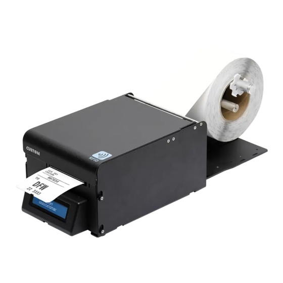
- Page 15 TK202III, TK302III 1. Power supply 2. Ruler 3. Documentation (short guide) 4. Serial cable 5. USB cable 6. Power supply cable 220V 7. Spacer for paper width < 40 mm 8. Device...
- Page 16 TK302III TF 1. Power supply 2. Ruler 3. Documentation (short guide) 4. Serial cable 5. USB cable 6. Power supply cable 220V 7. Device...
-
Page 17: Device Components: External Views
3.2 Device components: external views KPM302III 1. Print head group 7. Paper input 2. Device chassis 8. S2 key 3. External connector for low paper sensor 9. Status LED 4. Paper out 10. S1 key 5. Front cover 11. FF FORM FEED key 6. - Page 18 KPM302III EJ 1. Print head group 7. Paper input 2. Device chassis 8. S2 key 3. External connector for low paper sensor 9. Status LED 4. Paper out 10. S1 key 5. Front cover with ejector group 11. FF FORM FEED key 6.
- Page 19 KPM302III vSEL, KPM302III hSEL 1. Print head group 8. Opening lever for upper cover 2. Device chassis 9. Paper input 3. External connector for low paper sensor 10. S2 key 4. Paper out 11. Status LED 5. Sensor for tilting slide position 12.
- Page 20 KPM302III TF 1. Device chassis 9. Triple feeder 2. Print head group 10. Paper input feeder 1 3. Release lever for upper cover 11. Paper input feeder 2 4. LF LINE FEED key 12. Paper input feeder 3 5. FF FORM FEED key 13.
- Page 21 KPM302III TF-EJ 1. Device chassis 9. Triple feeder 2. Print head group 10. Paper input feeder 1 3. Release lever for upper cover 11. Paper input feeder 2 4. LF LINE FEED key 12. Paper input feeder 3 5. FF FORM FEED key 13.
- Page 22 KPM302III TF-hSEL 1. Device chassis 10. Paper input feeder 1 2. Print head group 11. Paper input feeder 2 3. Release lever for upper cover 12. Paper input feeder 3 4. LF LINE FEED key 13. Triple feeder LED (green) 5.
- Page 23 TK202III, TK302III 1. Paper out 2. FF FORM FEED key 3. LF LINE FEED key 4. Display 5. Captive knob for connector cover opening 6. Connectors cover 7. Internal printer (see previous pages) 8. Paper input...
- Page 24 TK302III TF 1. Paper out 2. FF FORM FEED key 3. LF LINE FEED key 4. Display 5. Internal printer with triple feeder (see previous pages) 6. Connectors cover 7. Captive knob for connector cover opening...
-
Page 25: Device Components: Connectors View
6. Power supply port KPM302III, KPM302III EJ, KPM302III vSEL, KPM302III hSEL KPM302III TF, KPM302III TF-EJ, KPM302III TF-hSEL, TK302III, TK302III TF TK202III NOTE: For ease of reference, for some models is represented only the internal printer group without external chassis or triple feeder. -
Page 26: Device Components: Internal View
3.4 Device components: internal view 1. Sensors for detecting paper out presence 2. Sensor for detecting the opening of the front cover 3. Sensor for detecting the cutter position (only for models with autocutter) 4. Unlocking button for mobile paper guide 5. -
Page 27: Device Labels
3.5 Device labels The main data used to identify the machine are shown on the label attached to the bottom of the device. In particular, it shows the electrical data for the connection to a power source. It also shows the product code, the serial number and the hardware revision (R). -
Page 28: Key Functions: Power Up
3.6 Key functions: power up POWER UP Hold down Hold down Hold down Print the SETUP report Perform the font test Initialize the black mark sensor with the printer parameters and characterize the paper Fast push Fast push Fast push Fast push Skip the SETUP procedure... - Page 29 Fast push Fast push Fast push Modify the Go to the Exit the SETUP selected parameter next parameter procedure NOTE: During power-up, do not press the S2 key because the device enter in a test modality that becomes unusable by keys; if this event occurs, turn of the device and turn on without pressing any key.
-
Page 30: Key Functions: Standby
Advance the paper Align the ticket and (manual feed) (preset length) perform the paper cut * NOTE: (*) Only with alignment enabled TK202III, TK302III, TK302III TF STANDBY Fast push Fast push Advance the paper Advance the paper (manual feed) (preset length) and... -
Page 31: Status Led Lashes
3.8 Status LED lashes The status LED indicates hardware status of device. Given in the table below are the various LED signals and the cor- responding device status. STATUS LED DESCRIPTION DEVICE OFF GREEN DEVICE ON: NO ERROR RECEIVE DATA RECEPTION ERRORS (PARITY, FRAME ERROR, OVERRUN ERROR) GREEN... -
Page 32: Triple Feeder Led Lashes
3.9 Triple feeder LED lashes KPM302III TF, KPM302III TF-EJ, KPM302III TF-hSEL, TK302III TF The LED panel of triple feeder is comprised of two LED (one of green colour and one of red colour) for each of the three paper input feeder. The LED indicate the triple feeder status and the paper status. -
Page 33: Messages On Display
3.10 Messages on display The display indicates the hardware status of device. Given in table below are the various display messages and the cor- responding device status. TK202III, TK302III, TK302III TF PRINTER READY RECEIVING DATA 01/01/21 12:00:00 SPOOLING..Device ON: no error... -
Page 35: Installation
4 INSTALLATION 4.1 Fixing brackets KPM302III, KPM302III EJ, KPM302III vSEL, KPM302III hSEL The device includes a kit for the assembly of two additional ixing brackets (see following igure). The kit contains: 1. No.2 ixing brackets; 2. No.4 ixing screws. For the assembly procedure, proceed as follows: Fix the bracket on Fix the bracket on the right side of the device. the left side of the device. - Page 36 The following igures (dimensions in millimetres) show the device overall dimensions with the two additional brackets. KPM302III M4 - N°4 holes 200.24 42.5 16.5 16.5 50.9 114.3...
- Page 37 KPM302III (CUT&DROP coniguration) M4 - N°4 holes 200.2 42.5 16.5 16.5 50.9 114.3...
- Page 38 KPM302III (BURSTER coniguration) M4 - N°4 holes 200.2 42.5 16.5 16.5 50.9 114.3...
-
Page 39: Fixing Slots
4.2 Fixing slots TK202III, TK302III, TK302III TF The device is provided with two slots for the mounting of the machine on desk. The slots are placed at the bottom of the machine (see following igure) SECTION D-D... - Page 40 The height A shown in the previous figure varies according to the accessory mounted to the device (see chapter 11). Arrange the desk with two fixing pins according to the measures shown in the previous page and the values of the height A listed in the table below.
-
Page 41: Burster Coniguration
4.3 BURSTER coniguration KPM302III, KPM302III TF The device includes a kit for BURSTER coniguration. The kit contains the upper mouth for paper out feed (see following igure). For the assembly procedure, proceed as follows: ATTENTION: Pay attention to the exposed cutter blade. Open the upper cover. - Page 42 Unscrew the fixing screws and remove the upper paper mouth for the standard configuration. paper mouth for paper mouth for standard BURSTER configuration configuration Unscrew the fixing screw and remove the light guide from the paper mouth for the standard configuration. Using the same screw, fix the same light guide to the paper mouth for the BURSTER configuration.
- Page 43 Unscrew the fixing pins and take off the fixed blade and the spring. Fix the paper mouth group for the BURSTER configuration by using the screws previously removed. NOTE: For ease of reference, for model with triple feeder is represented only the printer group without triple feeder.
-
Page 44: Cut&Drop Coniguration
4.4 CUT&DROP coniguration KPM302III, KPM302III TF The device includes a kit for the CUT&DROP coniguration (see the following igure). The kit contains: 1. Label 2. Lower paper out feed mouth. V I N I N G For the assembly procedure, proceed as follows: ATTENTION: Pay attention to the exposed cutter blade. Open the upper cover. - Page 45 Unscrew the fixing screws and remove the upper paper mouth for the standard configuration. Using a clamp, remove the precut sheet metal on the upper device cover.
- Page 46 Fix the upper paper group for the standard configuration in the upper holes on the cover using the screws previously removed. Unscrew the two fixing screws on the front cover and take off the lower paper mouth of the standard configuration.
- Page 47 Fix the lower paper mouth for the CUT&DROP configuration by using the screws previously removed. V I N I N G V I N I N G Close the upper cover and paste the label (supplied with the CUT&DROP kit) on the front cover. NOTE: For ease of reference, for model with triple feeder is represented only the printer group without triple feeder.
-
Page 48: Connections
4.5 Connections The following igure shows the possible connections for the device. When the RS232 and USB communication cables are connected to the printer at the same time, communication takes place via the USB port. KPM302III, KPM302III EJ, KPM302III vSEL, KPM302III hSEL KPM302III TF, KPM302III TF-EJ, KPM302III TF-hSEL RS232 standard cable Power supply cable (included) Serial standard cable ETHERNET ETHERNET UTP CrossOver... - Page 49 TK202III, TK302III, TK302III TF RS232 USB cable (included) Power supply cable (included) Serial cable (included) ETHERNET ETHERNET UTP CrossOver standard cable standard cable (pin-to-pin) Power supply USB device serial device only for TK302III, TK302III TF ATTENTION: In some using conditions, we recommend the installation of a ferrite core on the power supply cable.
-
Page 50: Pinout
4.6 Pinout POWER SUPPLY Male Molex connector vertical (no. 39-30-0060) 1 +24 Vdc 2 +24 Vdc 3 +24 Vdc 4 GND 5 GND 6 GND The following igure shows the connector pinout of power supply cable: Female connector 18 AWG cable Molex (n.39-01-2065) Cable Signal color +24V not connected +24V +24V Black not connected... - Page 51 RS232 SERIAL INTERFACE Female DB9 connector 1 DCD 2 TX During transmission, takes the values -VRS232 and + VRS232 depending on data 3 RX During reception, takes the values -VRS232 and +VRS232 depending on data 4 DSR 5 GND 6 DTR When +VRS232, device is power on 7 CTS 8 RTS...
- Page 52 KPM302III, KPM302III EJ, KPM302III vSEL, KPM302III hSEL KPM302III TF, KPM302III TF-EJ, KPM302III TF-hSEL, TK302III, TK302III TF ETHERNET INTERFACE Female RJ45 connector 1 TPOUT + 2 TPOUT - 3 TPIN + 4 GND 5 GND 6 TPIN - 7 n.c 8 n.c 9 +3.3 V 10 LED-LAN 11 +3.3 V...
-
Page 53: Driver And Sdk
4.7 Driver and SDK The drivers for the following operating system are available in the website www.custom4u.it. OPERATING SYSTEM DESCRIPTION INSTALLATION PROCEDURE Driver for Windows XP Driver for Windows VISTA (32/64bit) Driver for Windows 7 (32/64bit) From the START menu, press Run Driver for Windows 8 (32/64bit) and type-in the path where the SW Windows... -
Page 55: Operation
5 OPERATION 5.1 Adjusting paper width KPM302III, KPM302III EJ, KPM302III vSEL, KPM302III hSEL TK202III, TK302III Paper width may be adjusted from 40 mm to 82.5 mm by pressing the unlocking button and moving the adjustable paper guide as shown in the igure. - Page 56 To manage paper width from 20 mm to 40 mm, apply the spacer provided with the device on the adjustable paper guide (see following igure), then adjust the paper width. NOTE: For ease of reference, it is represented only the internal printer without external chassis.
-
Page 57: Adjusting The Alignment Sensors
5.2 Adjusting the alignment sensors The device is equipped with two mobile sensors for the detection of the alignment black mark placed both on the thermal side and on the non-thermal side of paper as shown in the following igure. The device user will need to manually move these mobile sensors according to the position and the type of the black mark on the paper. - Page 58 To adjust the mobile sensors position according to the black mark position and the type on paper, open the device cover and move the sensors to the desired position using a small screwdriver or a pointed object. ATTENTION: To avoid damaging the sensor, use the plastic tabs as foothold for the screwdriver to push the sensor in the desired position.
-
Page 59: Low Paper Sensor
5.3 Low paper sensor The device provides as accessories (see chapter 11) two kits which include a low paper sensor with the cable (see follow- ing igure). To ix the sensor, use an M3 screw not supplied. All the dimensions shown in following igures are in millimetres. MATERIAL NOT MATERIAL INCLUDED INCLUDED Fixing Low paper sensor Low paper screw M3 Connector Low paper wiring... - Page 60 Low paper wiring Connect the wiring coming from the low paper sensor board at the connector shown in figure.
-
Page 61: Switch The Device On
5.4 Switch the device on KPM302III, KPM302III EJ, KPM302III vSEL, KPM302III hSEL KPM302III TF, KPM302III TF-EJ, KPM302III TF-hSEL Power supply cable (included) EXTERNAL POWER SUPPLY UNIT (OPTIONAL) Connect the power supply cable to an external power supply unit. The green LED turn on and the device is ready. - Page 62 TK202III, TK302III, TK302III TF RS232 Rotate the captive knob to unlock the connectors cover. Power supply cable (included) <product code> R<n> <serial number> IN DC 24V 4.10A Connect the power supply cable to the device. Remove the Use the type of electrical power supply connectors cover.
- Page 63 Power supply (included) PRINTER READY 01/01/21 12:00:00 The display turns on with the standby message. The device is ready. 220V power supply cable (included) Connect the 220V power supply cable to the power supply unit and to outlet. ON/OFF Switch the device on by pressing the ON/OFF key on the power supply cable.
-
Page 64: Loading The Paper Roll
To change the paper proceed as follows. At every change of paper, check inside the device to locate and remove any scraps of paper. KPM302III, KPM302III EJ, KPM302III vSEL, KPM302III hSEL TK202III, TK302III TK202III, TK302III ATTENTION: Pay attention to the exposed cutter blade. - Page 65 ROOM Wait until the paper is automatically loaded. TK202III, TK302III Close the upper cover of the device. Close the Insert the paper into the input mouth so that it unrolls upper plastic cover. correctly. Be sure that the paper is...
- Page 66 KPM302III TF, KPM302III TF-EJ, KPM302III TF-hSEL, TK302III TF TK302III TF ATTENTION: Pay attention to the exposed cutter blade. Open the Open the upper cover upper plastic cover. of the device. Adjust the paper width and the position of Push the opening lever the black mark sensors in the direction shown in the figure.
- Page 67 ROOM Wait until the paper is automatically loaded. Close the upper cover of the device. TK302III TF ATTENTION: In case of ticket with TAG RFID, is recommended to insert the ticket into the central feeder (paper input feeder 2). The use of paper inputs 1 and 3 causes a slight bending of paper and therefore the integrity of the TAG RFID is not guarante- ed.
-
Page 68: Issuing Ticket
5.6 Issuing ticket The device allows you to choose between diferent operating modes for the issuance of printed tickets. The operating modes shown in following images, depend on the settings of coniguration parameters and commands sent to the device. NOTE: For ease of reference, for some models is represented only the internal printer group without external chassis or triple feeder. Standard mode (KPM302III, KPM302III EJ, KPM302III vSEL, KPM302III hSEL KPM302III TF, KPM302III TF-EJ, KPM302III TF-hSEL, TK302III, TK302III TF) Printhead Paper input The device starts the ticket printing. - Page 69 “PRESENT” mode (KPM302III EJ, KPM302III TF-EJ) Printhead Paper input The device starts the ticket printing. Ticket printed Ejector rollers Cutter When printing ends, the device cuts the ticket printed and hold it between the ejector rollers.
- Page 70 Ticket withdrew The user withdraws the ticket printed.
- Page 71 “EJECT” mode (KPM302III EJ, KPM302III TF-EJ) Printhead Paper input The device starts the ticket printing. Ticket printed Ejector rollers Cutter When printing ends, the device cuts the ticket printed and hold it between the ejector rollers.
- Page 72 Ticket ejected Ejectors rollers The device ejects the ticket printed. NOTE: To enable this issuing method, you need to correctly set the operation mode of the ejector device with the command 0x1D 0x65 0x05 (refer to the commands manual of the device).
- Page 73 “PRESENT” mode (KPM302III vSEL) Paper input Printhead The device starts the ticket printing.
- Page 74 Cutter Ejector rollers Ticket printed When printing ends, the device cuts the ticket printed and hold it between the ejector rollers. Ticket withdrew The user withdraws the ticket printed. NOTE: To enable this issuing method, you need to correctly set the operation mode of the selector device with the command 0x1D 0x70 0x6F (refer to the commands manual of the device).
- Page 75 “EJECT” mode (KPM302III vSEL) Paper input Printhead The device starts the ticket printing.
- Page 76 Cutter Ejector rollers Ticket printed When printing ends, the device cuts the ticket printed and hold it between the ejector rollers. Ejector rollers Ticket ejected The device ejects the ticket printed. NOTE: To enable this issuing method, you need to correctly set the operation mode of the selector device with the commands 0x1D 0x70 0x6F and 0x1D 0x65 0x05 (refer to the commands manual of the device).
- Page 77 “COLLECT” mode (KPM302III vSEL) Paper input Printhead The device starts the ticket printing.
- Page 78 Cutter Ejector rollers Tilting slide Ticket printed When printing ends, the device cuts the ticket printed and hold it between the ejector rollers. The tilting slide is lifted and the ticket printed is driven into the ejection canal. Ejector rollers Ticket withdrew The device collects the ticket printed.
- Page 79 “PRESENT” mode (KPM302III hSEL, KPM302III TF-hSEL) Printhead Paper input The device starts the ticket printing. Ticket printed Ejector rollers Cutter When printing ends, the device cuts the ticket printed and hold it between the ejector rollers.
- Page 80 Ticket withdrew The user withdraws the ticket printed. NOTE: To enable this issuing method, you need to correctly set the operation mode of the selector device with the command 0x1D 0x70 0x6F (refer to the commands manual of the device).
- Page 81 “EJECT” mode (KPM302III hSEL, KPM302III TF-hSEL) Printhead Paper input The device starts the ticket printing. Ticket printed Ejector rollers Cutter When printing ends, the device cuts the ticket printed and hold it between the ejector rollers.
- Page 82 Ticket ejected Ejectors rollers The device ejects the ticket printed. NOTE: To enable this issuing method, you need to correctly set the operation mode of the selector device with the commands 0x1D 0x70 0x6F and 0x1D 0x65 0x05 (refer to the commands manual of the device).
- Page 83 “COLLECT” mode (KPM302III hSEL, KPM302III TF-hSEL Printhead Paper input The device starts the ticket printing. Ticket printed Tilting slide Ejector rollers Cutter When printing ends, the device cuts the ticket printed and hold it between the ejector rollers. The tilting slide is lifted and the ticket printed is driven into the ejection canal.
- Page 84 Ticket withdrew Ejector rollers The device collects the ticket printed. NOTE: To enable this issuing method, you need to correctly set the operation mode of the selector device with the commands 0x1D 0x70 0x6F and 0x1D 0x65 0x05 (refer to the commands manual of the device).
-
Page 85: Configuration
6 CONFIGURATION 6.1 Coniguration by keys To enter the coniguration mode and print a setup report with the operating parameters of the device, proceed as follows. KPM302III, KPM302III EJ, KPM302III vSEL, KPM302III hSEL KPM302III TF, KPM302III TF-EJ, KPM302III TF-hSEL RS232 Power supply cable (included) While pressing the LF LINE FEED key, switch on the device by connecting the power supply cable. PRINTER SETUP The device prints the report with the settings parameters. - Page 86 TK202III, TK302III, TK302III TF While pressing the LF LINE FEED key, switch on the device by pressing the ON/OFF key on the power supply cable. PRINTER SETUP The device prints the report with the settings parameters. Follow the instruction printed on the paper...
- Page 87 The following igures show the setup reports of the device. The shown values for parameters are sample values; for the list and the description of device parameters see the following paragraphs. <device name> DEVICE NAME and SCODE: <code> rel 1.00 BCODE: <code> rel 1.00 FIRMWARE MODULES FCODE: <code> rel 1.00 UCODE: <code> rel 1.00 RELEASE DCODE: <code> rel 1.00 CPLD rel 1.00 PRINTER SETTINGS...
- Page 88 KPM302III, KPM302III EJ, KPM302III vSEL, KPM302III hSEL KPM302III TF, KPM302III TF-EJ, KPM302III TF-hSEL,,TK302III, TK302III TF [LF] enter Printer Setup [FF] enter Ethernet Setup KEYS FUNCTIONS [S1] enter Clock Setup [S2] skip Setup DHCP Client ........: Disabled FTP Server ........: Disabled IP Address .........
-
Page 89: Coniguration By Software
6.2 Coniguration by software The coniguration parameters can be set by the "PrinterSet” software tool available on www.custom4u.it. For a detailed description of operating parameters for the device, see the following paragraphs. To set the device by software, proceed as follows. Connect the device to a PC directly (see paragraph 4.5), without using HUB devices. Start “PrinterSet”... - Page 90 LOAD SAVE PORT SETUP FONTS UPGRADE H. reflect V. reflect Click on SETUP to access the operating parameteres of the device to be configured. PORT LOAD SAVE EXTRA SETUP Description <Parameter> Disabled Activation of the Bluetooth® module <Parameter> Enabled or WiFi on the device. If the “Wireless” parameter is set to ON (active) do not <Parameter>...
-
Page 91: Coniguration By Ile
6.3 Coniguration by ile The coniguration parameters can be set by editing the "Setup.ini” ile stored on the Flash Drive of the device. Proceed as follows: Enter setup Enter the coniguration procedure by keys (see paragraph 6.1) or by software (see paragraph 6.2). Plug the device to a Personal Computer via USB. <parameter> ....: <value> <parameter> ....: <value> <parameter> ....: <value> <parameter>... - Page 92 The “Setup.ini” ile is a coniguration ile that contains all the conigurable parameters listed in text format and divided into some sections (indicated between square brackets). For each parameter, you ind the parameter name followed by the value currently set and then the available values listed with a reference number. The reference number marked with the symbol ‘ * ’ is the default one (see following igure). Value set Section [PRINT] Parameter name Speed / Quality = 2 0 = High Quality 1 = Normal // * 2 = High Speed Availables values Default marker...
-
Page 93: Printhead Status
6.4 Printhead status The device performs the printhead operating status when printing the setup report. The total number of dots is reported Are indicated the total dots number of the printhead and their status (see igure below). SCODE. <code> rel 1.00 DCODE. <code> rel 1.00 FCODE. <code> rel 1.00 Total no. printhead dots PRINTER SETTINGS 1 «••••••••»... -
Page 94: Device Status
6.5 Device status The device operating status is indicated in the coniguration print-out in which, next to the name of the components dis- played, the following information is given: device model PRINTER TYPE BARCODE READER presence of the barcode reader RFID MODULE presence of the RFID reader/writer PRINTHEAD TYPE print head model INTERFACE interface present Ethernet connection type ETHERNET TYPE PROGRAM MEMORY TEST OK appears if functioning and NOT OK if faulty DYNAMIC RAM TEST... -
Page 95: Communication Parameters
6.6 Communication parameters The parameters marked with the symbol are the default values. Settings remain active even after the device has been turned of and they are stored in non-volatile memory. Communication speed of the serial interface. RS232 BAUD RATE 115200 9600 57600 4800 38400 2400 19200 1200 This parameter is valid only with serial interface. RS232 DATA LENGTH Number of bit used for characters encoding. - Page 96 Numerical address code for the univocal identiication of the USB device (in case of more USB ADDRESS NUMBER than a USB device connected with the same PC). None If the parameter is set on "None", the device is identiied by the physical USB port to which it is connected. RFID MODULE Communication speed of the RFID module. BAUD RATE 115200 9600 57600 4800 38400 2400 19200 1200 If the RFID module is not recognized in the printer status (“RFID module = Not Present”), set this parameter on the correct value.
- Page 97 This parameter identiies the Gateway IP address used to send applications to the external DEFAULT GATEWAY network. This parameter is present only for models with Ethernet interface. It can be modiied by software (see paragraph 6.2) and by ile (see paragraph 6.3). This parameter identiies the primary DNS server (Domain Name System). PRIMARY DNS SERVER This parameter is present only for models with Ethernet interface. It can be modiied by software (see paragraph 6.2) and by ile (see paragraph 6.3). This parameter identiies the secondary DNS server (Domain Name System). SECONDARY DNS SERVER This parameter is present only for models with Ethernet interface. It can be modiied by software (see paragraph 6.2) and by ile (see paragraph 6.3).
-
Page 98: Operation Parameters
6.7 Operation parameters The parameters marked with the symbol are the default values. Settings remain active even after the device has been turned of and they are stored in non-volatile memory. Available emulations for the device. PRINTER EMULATION SVELTA CUSTOM POS PRINT MODE Printing mode. Normal = enables printing in normal writing way Reverse = enables printing rotated 180 degrees AUTOFEED Setting of the Carriage Return character: CR disabled... - Page 99 Threshold value (in percent) for the recognition of the presence of paper by the paper PAPER THRESHOLD presence sensor. Enable or disable the autocutter at the hardware level: CUTTER Disabled = autocutter disabled Enabled = autocutter enabled For the device described in this document, keep this parameter set on "Enabled", as the default value.
- Page 100 This parameter enables/disables the block of the paper inside the device where the ticket TICKET LOCKING is not cut with the autocutter, but is presented for the manual tear of by the user: KPM302III, KPM302III EJ, KPM302III vSEL, KPM302III hSEL, TK302III Disabled paper block disabled Enabled = paper block enabled KPM302III TF, KPM302III TF-EJ, KPM302III TF-hSEL, TK302III TF Disabled paper block disabled By Printer =...
- Page 101 Identiier number of the character code page to use. CODE PAGE paragraph 9.12 to learn about the character tables corresponding to the identiication numbers set with this parameter. The character tables set with this parameter are the same set with the command 0x1B 0x74 (refer to the commands manual of the device). The numeric value of the identiier is made up with the following two parameters for the setting of two digits for the tens and the units: Setting the digit for tens: CODE PAGE [num x 10] Setting the digit for units:...
-
Page 102: Alignment Parameters
6.8 Alignment parameters The parameters marked with the symbol are the default values. Settings remain active even after the device has been turned of and they are stored in non-volatile me. Position of the alignment black mark and choice of appropriate black mark sensor (see BLACK MARK POSITION chapter Disabled = the black mark alignment is not performed Top ... - Page 103 For example, to set a positive black mark distance value of 15 mm, modify the parameters as follows: Black mark distance sign Black mark distance [mm x 10] Black mark distance [mm x 1] Black mark distance [mm x .1] If the “Black mark position”...
-
Page 104: Hexadecimal Dump
6.9 Hexadecimal dump This function is used for the diagnosis of the characters received from the communications port. Characters are printed as hexadecimal code and the corresponding ASCII code (see below). Each line is preceded by a counter in hexadecimal that indicates the number of bytes received. -
Page 105: Calendar Clock
6.10 Calendar clock The device is equipped with a Real Time Clock. During power-up, held down the LF LINE FEED key to enter in the device coniguration mode. Press the S1 key to enter in the clock coniguration (see following igure). Press the LF LINE FEED key to modify date/time; the device will print the updated date and time. Follow the instructions printed on the paper for the key functionality. - Page 106 TK202III, TK302III, TK302III TF The device is equipped with a Real Time Clock. Proceed as follows to perform the clock coniguration. 2 3 4 5 6 7 8 9 LF = ENTER SETUP... FF = EXIT SETUP... Clock Setup 01/01/21 12:00:00 During power-up, press the LF LINE FEED key to enter the setup configuration. The digit to be modified is highlighted.
-
Page 109: Alignment
7 ALIGNMENT The device is provided with sensors for the use of alignment black mark in order to handle: roll of tickets with pre-printed ields and a ixed length; • fan-fold module of tickets with pre-printed ields and a ixed length. • The alignment black mark may be formed by • a black mark printed on the paper; • a hole between two tickets;... -
Page 110: Enable Alignment
7.1 Enable alignment The device is provided with the two following sensors for alignment shown in igure: SENSOR 1, a mobile sensor placed on the lower lat, • SENSOR 2, a mobile sensor placed on the upper lat. • For ease of understanding, all the following images represent the two lats on the same plane. Moreover, for some models is represented only the internal printer group without external plastic chassis or triple feeder. SENSOR 1 SENSOR 2 upper flat lower flat To guarantee the alignment, it is necessary to correctly choose the sensor to use for the black mark detection depending on the type of black mark and its location on the ticket. - Page 111 The following igures show the usable format of paper and the corresponding sensors used for alignment: Paper with black mark on the non-thermal side direction paper feed NON-TERMAL SENSOR 1 SIDE...
- Page 112 Paper with black mark on the thermal side direction paper feed THERMAL SENSOR 2 SIDE...
- Page 113 Tickets with hole direction paper feed SENSOR 1 SENSOR 2...
- Page 114 Paper with labels (KPM302III, KPM302III EJ, KPM302III vSEL, KPM302III hSEL TK202III, TK302III) direction paper feed SENSOR 1 SENSOR 2...
-
Page 115: Calibration
7.2 Calibration The sensor calibration occurs automatically and consists in adjusting the quantity of light emitted to match the degree of whiteness of the paper used and the degree of black of the mark printed on paper. The device automatically performs the self-calibration during the setup procedure only if the “Black mark position” parameter is set to a value other than “Disabled”... - Page 116 The following igure shows an example of paper with holes: the outgoing voltage is constant while passing the paper between two holes and presents a variation at each hole. In this case, the optimal value for the “Black mark threshold” parameter is placed about half of the variation. NON-THERMAL SIDE “Black mark threshold” Peak THERMAL SIDE...
- Page 117 The following igure shows an example of paper with the non-thermal paper printed with black marks and other graphics (for example, a barcode): the outgoing voltage is constant while passing the white paper between two black marks, presents a peak at each black mark and presents some “noise” at each barcode. In this case, the optimal value for the “Black mark threshold” parameter is located about halfway between the peak value and the maximum value of the “noise” (as shown in igure): NON-THERMAL SIDE Peak...
-
Page 118: Alignment Parameters
7.3 Alignment parameters The “alignment point” is deined as the position inside the ticket to use for the black mark alignment. The distance between the black mark edge and the alignment point is deined as “black mark distance”. The value of “black mark distance” varies from a minimum value of -5 mm to a maximum value of 66 mm. If the setup parameter "Black mark distance" value is set to 0, the alignment point is set at the beginning of the black mark (see following igure): Alignment Alignment... - Page 119 To set a negative value of "black mark distance" is useful when the alignment point refers to the black mark placed on the previous ticket or when the desiderd cutting line is placed in the middle of the alignment black mark (for example, for paper with holes or gap).
- Page 120 The following igure shows a simpliied section of the device with the paper path and the distances (in millimetres) between the alignment sensors, the print head and the cutter (cutting line, only for models with autocutter). cutting line printing line black mark sensors CUSTOM POS emulation To deine the alignment point you need to set the setup parameters that compose the numerical value of the parameter “Black mark distance” (see chapter For example, to set a black mark distance of 15 mm, the parameters must be set on the following values: Black mark distance sign Black mark distance [mm x 10] Black mark distance [mm x 1]...
- Page 121 SVELTA emulation The ticket features and the alignment parameters, may be modiied as follows: • by using the parameters of the <LHT> command (refer to the commands manual of the device) by ile (see paragraph • 6.3); • by software (see paragraph 6.2). The following igure shows some of the parameters for alignment: • “Ticket X Dimension” • “Ticket Y Dimension” • “Black mark Width” •...
-
Page 122: Printing Area
7.4 Printing area In order to print ticket containing only one black mark and to not overlay printing to a black mark (that will make it useless for the next alignment), it is important to well calibrate: • the length of the printing area of ticket according to the inter-black mark distance; the value for the paper recovery after a cut or a manual tear-of. - Page 123 H Distance between the irst and the last printing line, called “Height of the printing area”. Distance between an edge of the black mark and the next one, called “Inter-black mark distance”. Automatic feed for alignment at the next black mark. To use all the black marks on paper, you must comply with the following equation: ...
-
Page 125: Maintenance
8 MAINTENANCE 8.1 Printer paper jam In the following sequence of images, the procedure for solving the paper jam inside the printer is described. For some models, only the internal printer group is represented. KPM302III, KPM302III EJ, KPM302III vSEL, KPM302III hSEL KPM302III TF, KPM302III TF-EJ, KPM302III TF-hSEL Open the upper cover of the device (see previous paragraphs). - Page 126 ROOM Insert the paper (see previous paragraphs). Close the front cover of the device. Close the upper cover of the device (see previous paragraphs).
- Page 127 TK302III, TK302III TF Open the front cover of the device. Open the upper covers of the device (see previous paragraphs). TK302III Remove the damaged paper and check the presence for paper scraps inside the device. Carefully remove all Open the plastic paper scraps.
- Page 128 Close the upper covers of the device Close the front cover (see previous paragraphs). of the device. TK302III ROOM Insert the paper (see previous paragraphs). Close the plastic front cover.
- Page 129 TK202III Open the upper covers of the device (see previous paragraphs). Close the upper covers of the device (see previous paragraphs). ROOM Insert the paper (see previous paragraphs). Remove the damaged paper and check the presence for paper scraps inside the device. Carefully remove all...
-
Page 130: Triple Feeder Paper Jam
8.2 Triple feeder paper jam KPM302III TF, KPM302III TF-EJ, KPM302III TF-hSEL, TK302III TF In case of paper jam inside the triple feeder, the green led that corresponds to the input paper jammed lashes quickly. In this case, contact the customer service. The green LED for the feeder jammed flashes quickly. Contact the customer service (see chapter 12). NOTE: For ease of reference, in some igure is represented only the internal printer without the external chassis. -
Page 131: Planning Of Cleaning Operations
8.3 Planning of cleaning operations The regular cleaning of the device keeps the print quality and extends its life. The following table shows the recommended planning for the cleaning operations. If you use the device in dusty environ- ments, you must reduce the intervals between cleaning operations. For speciic procedures, see paragraph 8.4. -
Page 132: Cleaning
8.4 Cleaning For periodic cleaning of the device, see the instructions below. For ease of reference, for some models is represented only the printer group without external chassis or triple feeder. Case Display Disconnect the power supply cable. Disconnect the power supply cable. ATTENTION: ATTENTION: Do not use alcohol, solvents, or hard brushes. - Page 133 Printhead Platen roller Disconnect the power supply cable and Disconnect the power supply cable and open the device covers (see previous paragraphs). open the device covers (see previous paragraphs). ISOPROPYL ALCOHOL ISOPROPYL ALCOHOL ATTENTION: ATTENTION: Do not use solvents, or hard brushes. Do not use solvents, or hard brushes.
- Page 134 Sensors Paper path Disconnect the power supply cable and Disconnect the power supply cable and open the device covers (see previous paragraphs). open the device covers (see previous paragraphs). ATTENTION: ATTENTION: Do not use alcohol, solvents, or hard brushes. Do not use alcohol, solvents, or hard brushes. Do not let water or other liquids get inside the machine.
- Page 135 Triple feeder Disconnect the power supply cable and open the device covers (see previous paragraphs). Contact the customer service (see chapter to request the kit for the triple feeder. ATTENTION: Do not use alcohol, solvents, or hard brushes. Do not let water or other liquids get inside the machine. To remove paper scraps, use tweezers or compressed air.
- Page 136 Autocutter Window for barcode reading Disconnect the power supply cable and Disconnect the power supply cable and open the device covers (see previous paragraphs). open the device covers (see previous paragraphs). ATTENTION: ATTENTION: Do not use alcohol, solvents, or hard brushes. Do not use alcohol, solvents, or hard brushes.
-
Page 137: Upgrade Irmware
8.5 Upgrade irmware Firmware upgrade can be performed by using the “PrinterSet” software tool available on www.custom4u.it. To upgrade irmware, proceed as follows. LOAD SAVE PORT From Device From File Login to the website www.custom4u.it, type in the prod- uct code of the device and download the latest irmware release available. Select a configuration file as follows: Click on LOAD >... -
Page 139: Specification
(only for models with selector) MTBF 84080 hours Noise KPM302III 74 dB KPM302III TF 75 dB TK202III TK302III 76.7 dB TK302III TF Emulations CUSTOM/POS, SVELTA INTERFACES USB port 480 Mbit/s... - Page 140 Thermal rolls, heat-sensitive side on outside of roll Type of paper Thermal fan-fold module with alignment black mark Paper width KPM302III TK202III from 20 mm to 82.5 mm (2 mm step) TK302III KPM302III EJ KPM302III vSEL from 40 mm to 82.5 mm (2 mm step)
- Page 141 40 mm to 82.5 mm (2 mm step) Paper weight modelli seguenti in conigurazione standard: KPM302III KPM302III EJ from 80 g/m to 255 g/m KPM302III vSEL KPM302III hSEL TK202III TK302III following models in BURSTER coniguration: KPM302III KPM302III EJ from 100 g/m to 250 g/m KPM302III vSEL KPM302III hSEL...
- Page 142 Core thickness 2 mm (+1 mm) Core type Cardboard or plastic Paper end Not attached to roll core AUTOCUTTER (only for models with autocutter) Paper cut Total cut Estimated life 1500000 cuts TRANSPONDER SPECIFICATIONS (only for models with RFID reader/writer) Supported transponders UHF ultra high frequency RFID UHF EPC Gen2...
- Page 143 0.14 A POWER SUPPLY ELECTRICAL SPECIFICATIONS code 963GE020000112 (OPTIONAL for KPM302III, KPM302III EJ, KPM302III vSEL, KPM302III hSEL, KPM302III TF, KPM302III TF-EJ, KPM302III TF-hSEL; INCLUDED with TK202III, TK302III, TK302III TF) Power supply voltage Auto Range, 90-132 VAC & 190-264 VAC Frequency...
- Page 144 TK202III TK302III from 0 °C to +40 °C TK302III TF Relative humidity (RH) KPM302III KPM302III EJ KPM302III vSEL KPM302III hSEL from 10% to 80% (w/o condensation) KPM302III TF KPM302III TF-EJ KPM302III TF-hSEL TK202III TK302III from 10% to 85% (w/o condensation)
-
Page 145: Character Speciications
9.2 Character speciications Character set Character density 11 cpi 15 cpi 20 cpi Number of columns Chars / second 2900 3800 5300 Lines / second Characters (L x H mm)-Normal 2.25 x 3 1.75 x 3 1.25 x 3 NOTE: Theoretical values. -
Page 146: Device Dimensions
9.3 Device dimensions All the dimensions shown in the following igure are in millimetres and referred to devices with covers closed and without paper roll. KPM302III, KPM302III EJ, KPM302III vSEL, KPM302III hSEL Length KPM302III 191 mm KPM302III EJ 212.7 mm KPM302III vSEL 272.2 mm KPM302III hSEL Height 123 mm Width 160 mm Weight 3500 g... - Page 147 KPM302III (standard coniguration) M4 - N°4 holes 200.24 42.5 50.9 114.3...
- Page 148 KPM302III (CUT&DROP coniguration) M4 - N°4 holes 200.2 42.5 50.9 114.3...
- Page 149 KPM302III (BURSTER coniguration) M4 - N°4 holes 200.2 42.5 50.9 114.3...
- Page 150 KPM302III EJ 23.1 21.8 211.8...
- Page 151 KPM302III vSEL 272.2...
- Page 152 KPM302III hSEL 272.2...
- Page 153 KPM302III TF, KPM302III TF-EJ, KPM302III TF-hSEL Length KPM302III TF 307.5 mm KPM302III TF-EJ 327 mm KPM302III TF-hSEL 385.2 mm Height 123 mm Width 168 mm Weight 5200 g...
- Page 154 KPM302III TF (standard coniguration) 67.5 94.6 86.5 2.5 Paper Out 5 - N°4 slots...
- Page 155 KPM302III TF (CUT&DROP coniguration) 67.5 94.6 5 - N°4 slots 90.4 10.1...
- Page 156 KPM302III TF (BURSTER coniguration) 67.5 94.6 86.5 2.5 Paper Out 5 - N°4 slots...
- Page 157 KPM302III TF-EJ 108.4 116.5 106.5 125.5...
- Page 158 KPM302III TF-hSEL 108.4 116.5 106.5 125.5...
- Page 159 TK302III, TK302III TF Length TK202III 252.1 mm TK302III TK302III TF 331 mm Height 192.6 mm Width 216 mm Weight TK202III 4000 g TK302III TK302III TF 4950 g...
- Page 160 TK202III, TK302III 103.4 paper in 38.4 Ø13 13.5 112.5 paper out...
- Page 161 TK302III TF 132.3 38.4 Ø13 13.5 112.5 paper out...
-
Page 162: Device Dimensions With Cut&Hold Kit
9.4 Device dimensions with CUT&HOLD kit code 976AV010000002 (optional) All the dimensions shown in the following igure are in millimetres and referred to devices with covers closed. KPM302III Length 214.1 mm Height 123 mm Width 160 mm M4 - N°4 holes 23.1 42.5 50.9 114.3... -
Page 163: Device Dimensions With Paper Roll Holder
9.5 Device dimensions with paper roll holder code 974BA010000001 (optional) All the dimensions shown in the following igure are in millimetres and referred to devices with covers closed and with Ø178 mm paper roll. TK202III, TK302III Length 463.1 mm Height 195.4 mm Width 216 mm 386.2 61.2 196.7 304.2 463.1 326.2 118.2... -
Page 164: Device Dimensions With Height Reduction Kit
9.6 Device dimensions with height reduction kit code 976BB010000014 (optional) All the dimensions shown in the following igure are in millimetres and referred to devices with covers closed and with Ø178 mm paper roll. models with paper roll holder (code 974BA010000001 - optional) Length 463.1 mm Height 185.9 mm Width 216 mm 386.2 61.2 196.7 304.2 463.1 326.2 118.2... -
Page 165: Device Dimensions With Power Supply Container
9.7 Device dimensions with power supply container code 974BB010000001 (optional) All the dimensions shown in the following igure are in millimetres and referred to devices with covers closed and with Ø178 mm paper roll. models with paper roll holder (code 974BA010000001 - optional) Length 463.1 mm Height 195.4 mm Width 216 mm 326.2 386.2 61.2 196.7 304.2 463.1 118.2... -
Page 166: Device Dimensions With Metallic Ticket Tray
9.8 Device dimensions with metallic ticket tray code 976BB010000003 (optional) All the dimensions shown in the following igure are in millimetres and referred to devices with covers closed TK302III, TK302III TF Length 464 mm Height 189 mm Width 216 mm 60° 61.2 135.6... -
Page 167: Device Dimensions With Plastic Ticket Tray
9.9 Device dimensions with plastic ticket tray code 976BD010000001 (optional) All the dimensions shown in the following igure are in millimetres and referred to devices with covers closed TK302III, TK302III TF Length 464 mm Height 192.6 mm Width 216 mm 211.6 252.1 61.2 135.6... -
Page 168: Dimensions Of Power Supply And Power Cord
The following table shows the dimensions of power supply unit and power cords available for the device. POWER SUPPLY code 963GE020000112 (OPTIONAL for KPM302III, KPM302III EJ, KPM302III vSEL, KPM302III hSEL, KPM302III TF, KPM302III TF-EJ, KPM302III TF-hSEL; INCLUDED with TK202III, TK302III, TK302III TF) Length 146.2 mm Height... - Page 169 POWER CORD code 26100000000311 2000 POWER CORD code 26100000000313 2000...
-
Page 170: Paper Speciication
9.11 Paper speciication Paper with black mark The following image shows the placement of the black mark on paper (dimensions in millimeters). The black mark can be printed both on the thermal side and on the non-thermal side of paper and it can be placed anywhere on the whole width of the paper. - Page 171 Paper with barcode (for models with barcode reader) The following image shows the placement of the barcode on the ticket (dimensions in millimeters). The barcode must be printed on the non-thermal side of the paper and at 25 mm from the edge of the ticket to ensure the correct barcode read- ing when ticket alignment is performed.
- Page 172 Fan-fold paper with hole (KPM302III, KPM302III EJ, KPM302III vSEL, KPM302III hSEL TK202III, TK302III) The following image shows the placement of the hole on the paper (dimensions in millimeters). The hole can be positioned across the width of the ticket. To manage tickets with hole, set the parameter "Black Mark position” to the value “Transparent” (see paragraph 6.8).
- Page 173 Fan-fold paper with hole (KPM302III TF, KPM302III TF-EJ, KPM302III TF-hSEL) The following image shows the placement of the hole on the paper (dimensions in millimeters). The hole can be positioned across the width of the ticket. To manage tickets with hole, set the parameter "Black Mark position” to the value “Transparent” (see paragraph 6.8).
- Page 174 Paper with labels (KPM302III, KPM302III EJ, KPM302III vSEL, KPM302III hSEL TK202III, TK302III) The following image shows a portion of paper with labels (dimensions in millimeters). To manage paper with label, you need to set a negative value for the parameter “Black mark distance” (see paragraph 6.8).
- Page 175 Ticket with RFID tag (models with RFID reader/writer) RFID (acronym for Radio Frequency IDentiication) is a technology to identify automatically items using radio waves; this system is based on wireless data capture from RFID tag using appropriate readers. The RFID tag, or transponder, is made up of: • the microchip that stores the data (including also a unique serial number written); •...
- Page 176 models with HF RFID module 36.5 printing line...
- Page 177 To use ticket with RFID tag with models with triple feeder, it is recommended to load ticket into the input feeder 2 (the central one), as shown in following igure. The use of paper inputs 1 and 3 causes a slight bending of paper and therefore the integrity of TAG RFID is not guaranteed. Before proceeding, check with a sample ticket.
-
Page 178: Character Sets In Custom/Pos Emulation
9.12 Character sets in CUSTOM/POS emulation The device has 3 fonts of varying width (11, 15 and 20 cpi) which may be related one of the coding tables provided on the device. To know the coding tables actually present on the device, you need to print the font test (see paragraph 3.6). - Page 179 <CodePage> Coding table PC861 - Icelandic on request PC862 - Hebrew PC864 - Arabic PC869 - Greek on request ISO8859-2 - Latin 2 on request ISO8859-15 - Latin 9 on request PC1098 - Farsi PC1118 - Lithuanian on request PC1119 - Lithuanian on request PC1125 - Ukrainian WPC1250 - Latin 2...
-
Page 180: Character Sets In Svelta Emulation
9.13 Character sets in SVELTA emulation In SVELTA emulation the device has 18 embedded fonts of varying width which may be accessed through control char- acters (see commands description in SVELTA emulation of command manual). The following list shows the font available and relative dimensions in dot: ... -
Page 181: Consumables
THERMAL PAPER ROLL weight = 180 g/m width = 80 mm Ø external = 180 mm Ø core = 25 mm TK202III, TK302III, TK302III TF 67A00000000304 FAN-FOLD (100 tickets) weight = 140 g/m dimensions = 152 mm x 80 mm... -
Page 183: Accessories
11 ACCESSORIES The following table shows the list of available accessories for device. 918AV030200000 KIT UHF RFID (for technical speciications, see paragraph 9.1) 918AV030100000 KIT HF RFID (for technical speciications, see paragraph 9.1) KPM302III, KPM302III EJ, KPM302III vSEL, KPM302III hSEL 26300000000452 WIRING KIT WITH LOW PAPER SENSOR length = 330 mm 26300000000599 WIRING KIT WITH LOW PAPER SENSOR length = 600 mm... - Page 184 KPM302III TF, KPM302III TF-EJ, KPM302III TF-hSEL, TK302III TF 26300000000453 WIRINGS KIT WITH LOW PAPER SENSORS length = 2 m (see paragraph 11.2) KPM302III, KPM302III EJ, KPM302III vSEL, KPM302III hSEL KPM302III TF, KPM302III TF-EJ, KPM302III TF-hSEL 963GE020000112 POWER SUPPLY (for technical speciications, see paragraph 9.1) 26100000000311 MAINS CABLE SHUKO PLUG length = 2 m...
- Page 185 KPM302III, KPM302III TF 976AV210000001 EJECTOR DEVICE 976AV210000002 SELECTOR DEVICE FOR HORIZONTAL FIXING (To use this accessory, it is necessary to set the setup parameter "Selector" on the "Enabled" value - see paragraph 6.7) 976AV210000003 SELECTOR DEVICE FOR VERTICAL FIXING (To use this accessory, it is necessary to set the setup parameter "Selector"...
- Page 186 TK202III, TK302III 974BA010000001 PAPER ROLL HOLDER 976BB010000014 KIT FOR HEIGHT REDUCTION (only for models with paper roll holder code 974BA010000001) 976BB010000001 KIT FOR POWER SUPPLY CONTAINER (only for models with paper roll holder code 974BA010000001)
- Page 187 TK302III, TK302III TF 26500000000357 USB CABLE with 90 degree connector length = 1.8 m 26500000000048 USB CABLE with 90 degree connector length = 3 m 26500000000331 SERIAL CABLE with 90 degree connector length = 1.8 m 26500000000043 SERIAL CABLE with 90 degree connector length = 3 m 26100000000311 MAINS CABLE SHUKO PLUG...
- Page 188 976BD010000001 PLASTIC TICKET TRAY 976BA010000323 KIT FOR BURSTER CONFIGURATION...
-
Page 189: Paper Roll Holder
11.1 Paper roll holder code 974AU010000305 (optional) For the device is available an external paper roll holder kit, supplied as accessory. The kit makes it possible to use paper rolls with larger diameter (up to 150 mm). The following igure shows the dimensions for holder support and paper roll pin (all the dimensions in igure are in mil- limetres). Ø max. 150 Ø... -
Page 190: Wirings Kit With Low Paper Sensor Boards
11.2 Wirings kit with low paper sensor boards code 26300000000453 (optional) For the device is available a kit of wirings with low paper sensor, supplied as accessory. The kit makes it possible the con- nection between triple feeder and low paper sensors. The kit includes three wirings assembled with three low paper sensors boards, as shown in following igure For the assembly procedure, proceed as follows: Remove the cover for the triple feeder connectors... -
Page 191: Technical Service
12 TECHNICAL SERVICE In case of failure, contact the technical service accessing the website www.custom4u.it and using the support tools on the homepage. It is advisable to keep the identiication data of the product at hand. The product code, the serial number and the hardware release number can be found on the product label (see paragraph 3.5). - Page 192 CUSTOM S.p.A. World Headquarters Via Berettine, 2/B - 43010 Fontevivo, Parma ITALY Tel. +39 0521 680111 - Fax +39 0521 610701 info@custom.biz - www.custom.biz All rights reserved www.custom.biz...
Need help?
Do you have a question about the TK202III and is the answer not in the manual?
Questions and answers