Table of Contents
Advertisement
Available languages
Available languages
Quick Links
G e n e r a l i n f o r m a t i o n :
ECP-024 is intended to be used with EMERSON's EXD-U01/U02 Universal Driver
Module and/or EXD-SH1/2 Stand Alone Superheat controller.
In case of power failure, ECP-024 insures that the valve is driven to the shut-off
position. ECP-024 can be connected to two EXD-...
S a f e t y i n s t r u c t i o n s :
• Read operating instructions thoroughly. Failure to comply can result in device
failure, system damage or personal injury.
• According to EN 13313 it is intended for use by persons having the
appropriate knowledge and skill.
• Do not exceed the specified maximum ratings for temperature, voltage and
current.
• Before installation or service disconnect all voltages from system and device.
• Ensure that design, installation and operation are according to European and
national standards/regulations.
• Do not operate system before all cable connections are completed.
• Disposal: ECP-024 contains lead acid gel rechargeable battery Electrical and
electronic waste must NOT be disposed of with other commercial waste.
Instead, it is the user responsibility to pass it to a designated collection point
for the safe recycling of Waste Electrical and Electronic Equipment (WEEE
directive 2012/19/EU). For further information, contact your local
environmental recycling center.
M o u n t i n g l o c a t i o n / I n s t a l l a t i o n :
• Protect ECP-024 against sunrays, heat and moisture.
• It is intended for installation in electrical switch
board/cabinet/box.
• On vertical walls, with output connectors on top
side.
• ECP-024 is delivered with bracket suitable for
mounting on DIN-Rail. Hang device above DIN-
Rail and push down- and backward until it snaps
completely and hold by DIN-Rail.
• Ventilation of electrical switch board/ cabinet /box
(natural or forced) is recommended in order to
reduce temperatures and consequently not to reduce
the life expectancy of the battery.
• Electrical Terminals K09-P00 (Part No. 804560) are
required.
W i r i n g : ( s e e F i g . 3 )
• It is mandatory the external grounding backside of ECP-024. (see Fig.1)
• Use a class II category transformer for 24 VAC power supply. Do not ground the
24 VAC line.
• See also operating instruction of Emerson EXD-U... and EXD-SH1/2.
• It is recommended to supply the ECP-024 from same source (e.g. transformer) as
the connected driver/controller.
• Recommended wire size Ø 0.5...2.5 mm
S e r v i c e :
• It is recommended that ECP-024 to be checked for proper function and life of
rechargeable batteries during regular system inspection. It is advisable to add the
following procedure to the service handbook of system/unit.
Emerson Climate Technologies GmbH
Am Borsigturm 31 I 13507 Berlin I Germany
Operating instructions
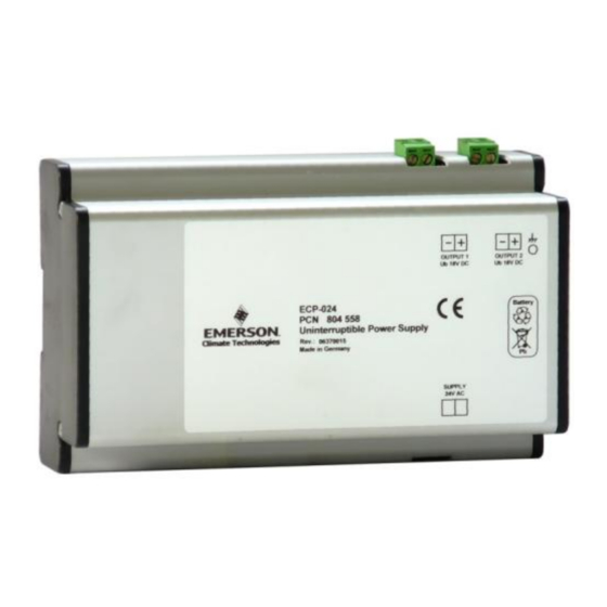
Uninterruptible Power Supply ECP-024
Fig.1:
ECP-024
Fig.2
:
K09-P00
(Part No. 804560)
2
.
www.climate.emerson.com/en-gb
T e s t o f b a t t e r y h e a l t h :
• Disconnect the wires from ECP-024.
• Connect a standard 22 Ω resistor with minimum 15 W capacity to one of output
power and a DC-voltmeter as shown in Fig. 4.
• Apply supply voltage 24 VAC to ECP-024 and measure the output power voltage.
It should be approximately 18.5 VDC.
• Disconnect the supply voltage 24 VAC from ECP-024 and watch the output
voltage. Power output must maintain at 18 VDC for minimum 5 seconds.
• ECP-024 always interrupts power output after 15 seconds when the supply voltage
24 VAC is disconnected.
B a t t e r y r e p l a c e m e n t i n s t r u c t i o n :
• In case of battery life end, follow the following procedures for replacement of both
batteries at the same time:
1. Disconnect the power and pull all green terminals from housing.
2. Unscrew both black plastics covers with star-key T-10 and remove them. (Fig. 5)
3. Pull out carefully the electronic board from right side. (Fig. 6)
4. Disconnect the connectors of each battery from the electronic board and remove
the soft dividing plate as well as both old batteries from the housing (Fig. 7)
5. Place carefully the new batteries inside of the housing, in the same position and
insert the soft dividing plate after batteries. (Fig. 8)
6. Connect the new batteries to the electronic board (Fig. 9)
7. The electronic board must be inserted in the two internal slots of housing
(Fig. 10).
8. Put back the cover plates, press them firmly to their place and tighten with screws
Ensure, that the small grey soft pads are placed correctly in the middle of the
black cover plates. (Fig. 11) Then connect all previously removed terminals and
attach by sticker the date of battery change.
9. Check the functionality of ECP-024 device like under point "Test of battery
health".
T e c h n i c a l D a t a :
Supply voltage
Number of power outputs
Number of internal batteries
Type of internal battery
Charging time
Ambient temperature
Electronic board temperature
Markings
Dimensions
ECP_OI_EN_DE_FR_ES_IT_RU_0820_R07_863031.docx
24 VAC ± 10%
Two, each approx. 18 VDC
Lead gel rechargeable battery,
12 VDC / 0.8 Ah
less than two hours
1...25 °C for optimum battery life time
> 35 °C lifetime of battery is maximum 2 years
according to EMC directive
Date: 27.08.2020
Two pieces
0...+65 °C
Advertisement
Table of Contents

Subscribe to Our Youtube Channel
Related Manuals for Emerson ECP-024


Summary of Contents for Emerson ECP-024
- Page 1 Module and/or EXD-SH1/2 Stand Alone Superheat controller. power and a DC-voltmeter as shown in Fig. 4. In case of power failure, ECP-024 insures that the valve is driven to the shut-off • Apply supply voltage 24 VAC to ECP-024 and measure the output power voltage.
- Page 2 • Montage auf senkrechten Flächen, Anschlüsse Batteriewechsels mit einem Aufkleber am ECP-anbringen. Fig.1: „Output1 – Output2“ oben. 9. Überprüfen Sie die Funktionalität des ECP-024 wie unter dem Punkt "Test der ECP-024 • ECP-024 wird mit einer Halterung geliefert, die für Batteriekapazität" beschrieben.
- Page 3 DC comme illustré en Fig. 4. En cas de défaillance d’alimentation, ECP-024 assure que la vanne est mise en • Appliquer une alimentation 24 VAC sur ECP-024 et mesurer la tension de sortie. position fermée. ECP-024 peut être connecté à deux régulateurs EXD-… .
- Page 4 CC como se muestra en la Fig. 4. manipulación puede acarrear lesiones al personal y desperfectos en el aparato • Aplique voltaje de suministro de 24 VCA a ECP-024 y mida el voltaje de potencia o en la instalación.
- Page 5 15 W e un voltmetro DC come mostrato in fig.4. In caso di mancanza di alimentazione, la batteria ECP-024 assicura la chiusura della • Alimentare a 24 VAC l’ECP-024 e misurare la tensione di uscita. Deve risultare di valvola. L’ECP-024 può essere collegato a due EXD-… .
- Page 6 выходе. Должно быть около 18.5 В постоянного тока. • Отключите питание 24 В переменного тока от ECP-024 и наблюдайте за И н с т р у к ц и я п о б е з о п а с н о с т и : напряжением...
- Page 7 EXD-U… / EXD-SH1/2 Fig./ Pис. 5: Fig./ Pис. 6 Fig./ Pис. 7 Fig./ Pис. 8 Fig./ Pис. 9 Fig./ Pис. 10 Fig./ Pис. 11 Emerson Climate Technologies GmbH www.climate.emerson.com/en-gb Date: 27.08.2020 Am Borsigturm 31 I 13507 Berlin I Germany ECP_OI_EN_DE_FR_ES_IT_RU_0820_R07_863031.docx...
Need help?
Do you have a question about the ECP-024 and is the answer not in the manual?
Questions and answers