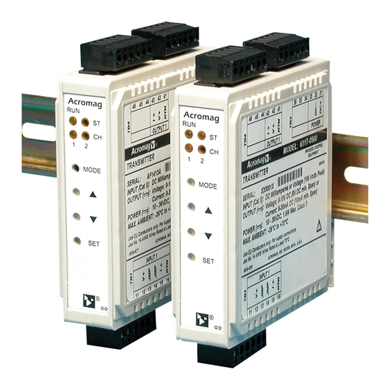
Summary of Contents for Acromag 611T Series
- Page 1 (217) 352-9330 | Click HERE Find the Acromag 612T-0500 at our website:...
- Page 2 Wixom, MI 48393-7037 U.S.A. Tel: (248) 624-1541 Fax: (248) 624-9234 Copyright 1999, Acromag, Inc., Printed in the USA. Data and specifications are subject to change without notice. 8500-602-G06G002 Artisan Technology Group - Quality Instrumentation ... Guaranteed | (888) 88-SOURCE | www.artisantg.com...
-
Page 3: Table Of Contents
Table 1: Models Covered in This Manual The information contained in this manual is subject to change Series/ -Options/Output/ -Factory without notice. Acromag, Inc., makes no warranty of any kind Input/Type Enclosure/Approvals Configuration with regard to this material, including, but not limited to, the... -
Page 4: Key 61Xt Isolator Features
The following accessory is available from Acromag which Key 61xT Features allows AC currents to be input to this module, and other modules that support DC current inputs. Acromag offers a full line of other • Wide-Range Universal Input & Output Ranges - Supports standard and custom transmitter, isolator, and alarm types to process current or voltage in user-configured ranges. -
Page 5: Preparation For Use
For repairs to a product damaged in DIN Rail Mounting: This module can be mounted on "T" shipment, refer to the Acromag Service Policy to obtain return type DIN rails. Use suitable fastening hardware to secure the instructions. It is suggested that salvageable shipping cartons DIN rail to the mounting surface. -
Page 6: Module Configuration
Series 611T/612T Isolator User's Manual Universal DC Voltage/Current Input ___________________________________________________________________________________________ 3. AC Current Input (Optional): Refer to Drawing 4501-734 to Configuration of I/O zero & full-scale is accomplished via the connect the optional AC current sensor. The sensor is transmitter module’s “SET”, “MODE”, “UP”, and “DOWN” push typically mounted near the AC current being measured and buttons, and the module’s status LED’s (see Drawing 4501-733) will transmit a low level DC milliampere signal to the module. - Page 7 Series 611T/612T Isolator User's Manual Universal DC Voltage/Current Input ___________________________________________________________________________________________ CAUTION: Do not insert sharp or oversized objects into the For a reverse acting output, you would adjust the output push-button switch openings as this may damage the unit. When level to a higher level in response to the zero input here, and depressing the push-buttons, use a blunt tipped object and apply a lower level in response to a full-scale input in Step 6.
-
Page 8: Theory Of Operation
Acromag for repair. The board can be damaged 4. If you want to calibrate a bipolar range that is non-symmetric unless special SMT repair and service tools are used. -
Page 9: Model Number Definition
Series 611T/612T Isolator User's Manual Universal DC Voltage/Current Input ___________________________________________________________________________________________ MODEL NUMBER DEFINITION Input Bias Current: ±100nA maximum, excluding excitation current of process current inputs. Transmitters are color coded with a white label. The prefix “6” Input Filter: Normal mode filtering, plus digital filtering, optimized and fixed per input range within the Σ-∆... -
Page 10: Enclosure/Physical Specifications
Series 611T/612T Isolator User's Manual Universal DC Voltage/Current Input ___________________________________________________________________________________________ ENVIRONMENTAL SPECIFICATIONS Output Resolution: Varies with calibrated output range. Nominal resolution is 1 part in 6644 (12.7 bits) and based on a 0-20mA, or 0-10V, nominally calibrated output Operating Temperature: -25°C to +70°C (-13°F to +158°F). range. -
Page 11: Configuration Controls & Indicators
Series 611T/612T Isolator User's Manual Universal DC Voltage/Current Input ___________________________________________________________________________________________ CONFIGURATION CONTROLS & INDICATORS Notes: Units are configurable via push-buttons and status indicators on the front panel of the module. These controls and indicators operate as follows: Module Push Buttons (See Dwg 4501-733 for Location): Mode - Used to change between Run and Configuration Modes. -
Page 12: Simplified Schematic (4501-731)
SCREW TERMINAL NUMBER INPUT CONDITIONING CH1 Switches Are Shorts For Single Channel Version (611T) -100V to +100V ISOLATED OUTPUTS 100K (1V MIN SPAN) SSR's -1.0V to +1.0V VOLTAGE TO (40mV MIN SPAN) FILTER CURRENT OPTIONAL LOW-V INPUT CONVERTER (JUMPER REMOVED) 0-100mA (4mA MIN SPAN) 10.0... -
Page 13: Electrical Connections (4501-732)
AND ARE NOT ISOLATED EARTH NOTE 1 OUTPUT-TO-OUTPUT GROUND NOTE 1 TWO-WIRE TRANSMITTER DC CURRENT INPUT (mA) Acromag RUN/PWR LED (GREEN) 44 43 STATUS LED (YELLOW) 36 35 PLACE A JUMPER WIRE BETWEEN JMP TERMINALS CHANNEL 2 LED (YELLOW) +/-1V to +/-100V DC RANGES... -
Page 14: Ac Sensor Connections (4501-734)
AC CURRENT SENSOR BLACK 0 TO 2A AC CURRENT ONLY. 0 TO 1A SENSOR FIGURE 3 EARTH GROUND DO NOT CONNECT ACROMAG MODEL 5020-350 AC CURRENT SEE NOTE 1 AC CURRENT DIRECTLY 20 AMPS DANGER: FULL-SCALE TO INPUT TERMINALS. (1-TURN) -
Page 15: Enclosure Dimensions (4501-733)
Acromag "T" RAIL DIN MOUNTING DIN EN 50022, 35mm MODE SCREWDRIVER SLOT FOR REMOVAL FROM "T" RAIL 3.90 1.05 (99.1) (26.7) 4.35 (110.5) NOTE: ALL DIMENSION ARE IN INCHES (MILLIMETERS) SERIES 611T/612T TRANSMITTER ENCLOSURE DIMENSIONS 4501-733A Artisan Technology Group - Quality Instrumentation ... Guaranteed | (888) 88-SOURCE | www.artisantg.com...


Need help?
Do you have a question about the 611T Series and is the answer not in the manual?
Questions and answers