
Related Manuals for Baroness LM551


Summary of Contents for Baroness LM551
- Page 1 5-Unit Reel Mower Owner's Operating Manual Serial No. LM551:10001- "Required reading" Read this manual and the Owner's Manual for the engine before using the machine. Original Instructions Ver.1.0...
- Page 2 LM551 Greeting Thank you for purchasing the Baroness product. This manual describes the proper handling, adjustment, and inspection of your product. We hope you will use the product safely, and take advantage of its best performance. For details on the handling, adjustment and inspection of the attachments, refer to the Owner's Operating Manual for the attachments.
- Page 3 The operator is responsible for operating the product properly and safely. Maintenance should only be performed by a certified specialist. If you have any questions concerning maintenance or genuine parts, please contact your local Baroness dealer or Kyoeisha. When making inquiries about the product, please specify the product's model designation and serial number.
- Page 4 When replacing parts, be sure to use genuine Baroness parts or parts designated by Kyoeisha. Note that the Baroness product warranty may not apply to defects caused by the use of parts from other companies. Prior to use, carefully read the following manuals to thoroughly understand the contents for safe and correct operation.
-
Page 5: Table Of Contents
LM551 Contents Safety .............. Page 1-1 Safe Operating Practices .......Page 1-2 Disposal ............Page 2-1 Recycle and Waste Disposal ......Page 2-2 Product Overview .......... Page 3-1 Specifications ..........Page 3-2 Names of Each Section ......... Page 3-4 Safety Signs and Instruction Signs ....Page 3-6 Handling Instructions ........ - Page 6 LM551 Contents...
-
Page 7: Safety
LM551 Safety Safe Operating Practices ...... Page 1-2 Training ..........Page 1-2 Preparation ..........Page 1-2 Operation ..........Page 1-3 Maintenance and storage ...... Page 1-4 Page 1-1... -
Page 8: Safe Operating Practices
LM551 Safety Failure to adequately follow these safety Never allow children or people unfamiliar precautions may cause an accident resulting in with these instructions to use or service the injury or death. machine. Local regulations may restrict the age of the... - Page 9 LM551 Safety Add fuel before starting the engine. Never Never operate across the face of the remove the cap of the fuel tank or add fuel slope, unless the machine is designed for while the engine is running or when the this purpose.
- Page 10 LM551 Safety Never operate while people, especially To reduce the fire hazard, keep the engine, children, or pets are nearby. silencer/muffler, battery compartment fuel storage area, cutting unit and drives free of Slow down and use caution when making grass, leaves, or excessive grease. Clean up turns and crossing roads and sidewalks.
- Page 11 LM551 Safety Make sure that parts such as wires are not touching each other and that their covers have not come off. Use care when checking the cylinders/reels and bed knives. Wear gloves and use caution when servicing them. Be careful during adjustment of the...
- Page 12 LM551 Safety Page 1-6 Safe Operating Practices...
-
Page 13: Disposal
LM551 Disposal Recycle and Waste Disposal ....Page 2-2 About Recycle ........Page 2-2 About the Waste disposal ...... Page 2-2 Page 2-1... -
Page 14: Recycle And Waste Disposal
LM551 Disposal Recycle and Waste Disposal About Recycle Recycling battery etc. is recommended for environmental conservation and economical use of resources. It may be required by local laws. About the Waste disposal Make sure that waste generated when servicing or repairing the machine is disposed of in accordance with local regulations. -
Page 15: Product Overview
LM551 Product Overview Specifications ........Page 3-2 Specifications .........Page 3-2 Sound pressure level ......Page 3-3 Sound power level ......... Page 3-3 Vibration level ........Page 3-3 Names of Each Section ......Page 3-4 Serial Number Plate .......Page 3-4 Specification Decal ........ Page 3-5 Noise Emission Decal ......Page 3-5... -
Page 16: Specifications
LM551 Product Overview Specifications Specifications Model LM551 Mower unit type 22 in Total length 116.14 in 295 cm Total width 86.61 in 220 cm Dimensions Roof 94.09 in 239 cm Total height Handle 62.99 in 160 cm with Groomer, CR... -
Page 17: Sound Pressure Level
LM551 Product Overview LH52 0.197 - 0.787 in 5.0 - 20.0 mm Operating height (Mowing LH62・66 0.315 - 1.772 in 8.0 - 45.0 mm height) LS62・66 0.394 - 1.811 in 10.0 - 46.0 mm Traveling HST (Full time 4WD) Drive... -
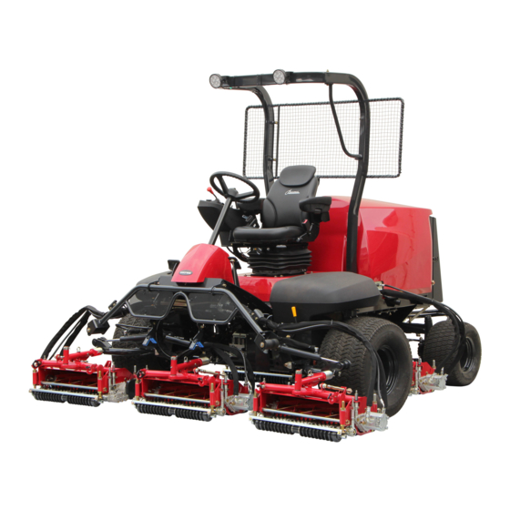
Page 18: Names Of Each Section
LM551 Product Overview Names of Each Section 10,11 quwxcl-098 Names of Each Section_002 quwxcl-097 Serial number plate Names of Each Section_001 Specifications decal Steering wheel Noise emission decal Tilt lever Year of manufacture decal Seat ROPS authentication decal Hood Battery capacity decal... -
Page 19: Specification Decal
LM551 Product Overview Specification Decal ROPS Authentication Decal (For Europe) The ROPS authentication decal indicates the The Specification decal indicates the CE manufacturer, model, etc., in accordance with marking, model , and weight, etc. International Standard ISO 21299:2009. kj8jic-001 c3td3e-003... -
Page 20: Safety Signs And Instruction Signs
Part numbers for decals that need to be replaced are listed in the parts catalog. 6iul4h-133 Order them from a Baroness dealer or Positions of Safety Signs and Instruction Signs_001 Kyoeisha. 6iul4h-134 Positions of Safety Signs and Instruction Signs_002... - Page 21 LM551 Product Overview 6iul4h-136 Positions of Safety Signs and Instruction Signs_004 6iul4h-137 Positions of Safety Signs and Instruction Signs_005 6iul4h-138 Positions of Safety Signs and Instruction Signs_006 Safety Signs and Instruction Signs Page 3-7...
-
Page 22: Description Of Safety Signs And Instruction Signs
LM551 Product Overview Description of Safety Signs and Instruction Signs LM2400-0918Z0 Decal for operation 2 Warning Read the Owner's Operating Manual. Warning Apply the parking brake, stop the engine, remove the ignition key, and then leave the machine. - Page 23 LM551 Product Overview K4205001540 Decal, caution to hot parts Caution High temperature - Do not touch. Otherwise, you will K 4 2 0 5 0 0 1 5 4 0 get burned. qigqnx-022 K4205001580 Decal, caution to injure Caution May pinch - There is a risk of being pinched.
- Page 24 LM551 Product Overview K4209000980 Decal, hydraulic oil Read the Owner's Operating Manual. K 4 2 0 9 0 0 0 9 8 0 qigqnx-020 K4209001000 Decal, diesel fuel refueling hole Use diesel fuel. K 4 2 0 9 0 0 1 0 0 0...
-
Page 25: Handling Instructions
LM551 Handling Instructions Inspection Before Use ......Page 4-2 Proximity Sensor ........Page 4-28 Relays ..........Page 4-28 Radiator Cover ........Page 4-2 Light Switch ......... Page 4-29 Radiator ..........Page 4-2 Traveling/Working Selector Switch ..Page 4-29 Coolant ..........Page 4-3 Reel Rotation Switch ......Page 4-29 Oil cooler ..........Page 4-4... -
Page 26: Inspection Before Use
LM551 Handling Instructions Make sure that the radiator is not Inspection Before Use contaminated. Be sure to perform an inspection before you Cleaning of Radiator start using the machine so that you will be able to take advantage of its optimum performance Important for a long period of time. -
Page 27: Coolant
LM551 Handling Instructions Pull up the radiator cover to remove it. Carefully clean the radiator with water or compressed air. Coolant Inspection of Coolant Caution Do not touch the radiator or coolant during engine operation or immediately after the engine has been turned off. -
Page 28: Oil Cooler
LM551 Handling Instructions If no coolant is in the reserve tank, follow Coolant Supply the steps below to supply clean water (soft water). Caution Open the radiator cap, and then supply Do not touch the radiator or coolant during clean water (soft water) up to the engine operation or immediately after the opening. -
Page 29: Hydraulic Oil
LM551 Handling Instructions Open the radiator cover. Supply of Hydraulic Oil Unlock the rubber catches on the left and right of the oil cooler, and then tilt the oil Important cooler. Do not mix different types of oil. Important Use Shell Tellus S2M46 (or equivalent) as hydraulic oil. -
Page 30: Air Cleaner
LM551 Handling Instructions Start the engine, raise and lower the mower Cleaning of Air Cleaner units, and turn the steering wheel right and left. A contaminated air cleaner element may Move forward and reverse repeatedly cause malfunction of the engine. -
Page 31: Battery
LM551 Handling Instructions Press the reset button for the vacuum indicator. 48yhlu-011 Inspection of Battery_001 yt4sup-017 Radiator cover Cleaning of Air Cleaner_002 Battery Reset button Clean the areas around the battery fluid Vacuum indicator level lines using a cloth dampened with Battery water. -
Page 32: Tire
LM551 Handling Instructions Supply of Battery Fluid Tire size Pneumatic pressure 120 kPa Front 26.5 x 14.00-12 Danger Danger wheel (1.2 kgf/cm 140 kPa Be careful not to let your skin, eyes or clothes, Rear 20 x 12.00-10 etc., come into contact with the battery fluid or wheel (1.4 kgf/cm... -
Page 33: Around The Engine
LM551 Handling Instructions Around the Engine Oil level gauge Upper limit Inspection of Engine-Associated Parts Lower limit Check the fuel system parts for loosened or Supply of Engine Oil cracked joints and leakage. Replace the parts if necessary. Important Blow compressed air to clean any grass or flammable materials that may be attached Do not supply too much engine oil. -
Page 34: Fuel
LM551 Handling Instructions Fuel Inspection of Fuel Quantity With the machine on a level surface, observe the fuel gauge in the operation panel to check the fuel level. 2e4emp-012 Supply of Fuel_001 Fuel tank Tank cap F U E L... -
Page 35: Water Separator
LM551 Handling Instructions Water Separator Inspection of Water Separator Important Water-contaminated fuel may impair engine startability, decrease output or damage engine parts. The water separator removes water from the v1spa6-005 fuel. Draining of Water Separator_001 Make sure that debris and water have not Fuel cock accumulated in the cup. - Page 36 LM551 Handling Instructions v1spa6-005 v1spa6-005 Draining of Water Separator_003 Cleaning of Water Separator_001 Fuel cock Fuel cock Air-bleeding plug Air-bleeding plug ON (open) ON (open) OFF (close) OFF (close) Loosen the air-bleed plug to bleed the air. Remove the ring nut, and then remove the cup.
-
Page 37: Fuel Filter
LM551 Handling Instructions Oil Leakage Inspection of Oil Leakage Caution When performing maintenance on the hydraulic system, lower the mower units. After approximately 50 hours of operation, some tightened portions may be loosened v1spa6-005 and oil and grease may leak. -
Page 38: Tightening Torques
LM551 Handling Instructions Tightening torques Important Refer to the Tightening Torque table. Note that the Baroness product warranty may not apply to defects caused by incorrect or overtorque tightening, etc. Standard tightening torques Bolts and Nuts Important A number of bolts are used in each part of this machine. - Page 39 LM551 Handling Instructions General bolt Strength classification 4.8 Nominal diameter tib3yb-001 kgf-cm lb-in 3 - 5 30.59 - 50.99 26.55 - 44.26 7 - 9 71.38 - 91.77 61.96 - 79.66 14 - 19 142.76 - 193.74 123.91 - 168.17 29 - 38 295.71 - 387.49...
-
Page 40: Principal Tightening Torques
LM551 Handling Instructions Principal tightening torques Tightening Torque by Model LM551 LM551A Tighten the following bolts and nuts at the torque specified in the table. For thread locking adhesive, apply a middle strength thread locker (ThreeBond 1322 or equivalent anaerobic sealant). -
Page 41: Adjustment Before Operating
LM551 Handling Instructions Adjustment Before Operating Tilt lever FREE (released) Adjustment of Steering Wheel LOCK (locked) Adjustment of Seat Warning Do not make adjustments while traveling since Use the adjustment levers to adjust the seat. doing so is dangerous. Adjust the position to fit the operator. -
Page 42: Adjustment Of Reel Rotation Control Valves
LM551 Handling Instructions Adjustment of Reel Rotation Control Important Valves In order to maintain quality mowing, the reel rotation speed must be the same for all mower The reel rotation control valves adjust the units. rotation speeds of the reel cutters (cutting cylinders). -
Page 43: Adjustment Of Mower Stopper Pin
LM551 Handling Instructions Note: Dial Raise the lock nut to a position where it will Lock nut not interfere when the dial is turned. Indicating screw Reel rotation label Use the specialized wrench (accessory) to tighten the lock nut for the dial. -
Page 44: Adjustment Of Mower Stabilizer
LM551 Handling Instructions To release: Insert the cotter pin into the lower hole in the mower stopper pin. 3ttzyg-002 Adjustment of Mower Stabilizer_001 Lock nut famlj4-004 Adjustment of Mower Stopper Pin_002 Spring Mower stopper pin 140.0 mm (5.51 in) Cotter pin... -
Page 45: Procedure To Start / Stop Engine
LM551 Handling Instructions Make sure that the traveling pedal is in Washer neutral position. Move the throttle lever from the "Low Length speed” position halfway toward the "High speed” position. Procedure to Start / Stop Engine Important Start / Stop of Engine... -
Page 46: Safety Mechanisms
LM551 Handling Instructions After the thermo-start lamp turns off, Close the fuel cock of the fuel filter. immediately set the ignition key to the Close the fuel cock of the water separator. "START" position. Safety Mechanisms Important This machine features a safety device for Quickly returning the ignition key from the starting/stopping the engine. -
Page 47: Operation Of Each Section
LM551 Handling Instructions Engine Overload Warning Buzzer If the traveling pedal is depressed and the speed exceeds 12.0 km/h while the pedal stopper is in the "OFF" position and the reel cutters (cutting cylinders) are rotating, a buzzer will sound. (intermittent tone) - Page 48 LM551 Handling Instructions 6n6oux-154 Operation Decals_005 Decal, reel rotation Decal, reel stop STOP Decal, key switch This indicates the key switch positions. 1. OFF 2. ON 3. GLOW 4. START 6n6oux-021 Decal, engine rotation This indicates the low/high speed of engine rotation.
- Page 49 LM551 Handling Instructions Decal, reel rotation switch It illustrates Rotation/Stop of the reel cutter (cutting cylinder). 1. Rotation 2. Stop 6n6oux-042 Decal, mower unit up/down lever This indicates the Up/Down positions of the mower unit. 1. Down 2. Up 6n6oux-041 Decal, traveling/working selector switch It illustrates ON/OFF of slight lift function.
- Page 50 LM551 Handling Instructions K4203001700 Decal, parking brake This shows how to lock and release the parking brake. 1. Lock 2. Release 6n6oux-157 K4203001450 BRAKE Decal, BRAKE This indicates brake. 6n6oux-132 K4203001430 Decal, FORWARD This indicates forward travel. 6n6oux-128 K4203001440 Decal, BACKWARD This indicates backward travel.
- Page 51 LM551 Handling Instructions K4203001720 Decal, open/close lever This indicates lock/release of open/close lever. 1. OPEN (release) 2. LOCK (lock) 6n6oux-158 K4203001590 Decal, lapping This indicates rotation direction of the reel cutter (cutting cylinder). 1. OFF (mowing rotation) 2. ON (back lapping rotation)
-
Page 52: Proximity Sensor
LM551 Handling Instructions Proximity Sensor Relays There are three proximity sensors on #1, #2, The relay box is located inside the underseat #4 and #5 mower arm fulcrums. cover. These sensors detect the raised or lowered These relays control traveling/working positions of mower units #1, #2, #4 and #5. -
Page 53: Light Switch
LM551 Handling Instructions When the switch is set to the "Traveling" Light Switch position, mower units #4 and #5 are raised to their highest positions. Caution When the switch is set to the "Working" position, mower units #4 and #5 are only raised The lights provide auxiliary lighting. -
Page 54: Reel Forward/Reverse Switch
LM551 Handling Instructions Note: When the mower units are raised, the reel cutters (cutting cylinders) do not rotate, even if the switch is set to the "Rotation" position. LAPP ING uy5vc2-001 Reel Forward/Reverse Switch_001 Reel forward/reverse switch Forward mh4pyw-013 Reverse... -
Page 55: Mower Lock Lever (Latch)
LM551 Handling Instructions Mower Lock Lever (Latch) The mower lock levers (latches) are located in the foot area on the left and right sides and are used when storing the machine with mower units #4 and #5 raised. When storing this machine, hook the mower lock levers (latches) on the arms. -
Page 56: Traveling Pedal
LM551 Handling Instructions Traveling Pedal Traveling pedal (forward) Traveling pedal (backward) The traveling pedal is located in the right foot Bolt area. Spring washer When forward depressed, the machine travels forward. When backward depressed, the Pedal Stopper machine travels backward. -
Page 57: Brake Pedal
LM551 Handling Instructions Brake pedal Locking pedal Release Lever The release lever is located at the lower-left side of the seat. This is used when opening and closing the underseat cover. When opening the underseat cover, raise the release lever to unlock. After closing the unp7tf-004 underseat cover, lock it. -
Page 58: Hood
LM551 Handling Instructions Radiator cover Rubber catch Rubber catch Catch clip Close the radiator cover slowly. Bolt Lock the rubber catch securely. Make sure that the radiator cover is closed. Hood Lift up the hood. Caution Do not open the hood in strong winds. -
Page 59: Instruments
LM551 Handling Instructions Instruments Steering wheel Seat Instruments on the Operation Panel Backrest While unlocking with the release lever, grab the grip and tilt the seat to the right to open the underseat cover. kz7ka6-015 Instruments on the Operation Panel_001... -
Page 60: Fuel Gauge
LM551 Handling Instructions Illumination of the thermo-start lamp is Fuel Gauge controlled by the glow lamp timer, and the lamp is turned off after a specified amount of The fuel gauge is located in the operation time passes. panel. The duration of illumination indicates an... -
Page 61: Travel Of Machine
LM551 Handling Instructions 1/10 wheel … black figures on a white Warning Buzzer background Hour wheel … white figures on a black There are two warning buzzers, which background indicate four warnings. ・ Warning buzzer 1 & 2 Warning buzzer 3 & 4 ・... -
Page 62: Towing The Machine
LM551 Handling Instructions Turn the unload valve under the seat 1 to 1.5 Towing the Machine turns counterclockwise. If the machine does not travel due to engine trouble, etc., you can move it in the following ways: Caution Do not touch the unload valve except when towing the machine. -
Page 63: Cutting Work
LM551 Handling Instructions Shift the throttle lever to rev the engine up to Cutting Work the maximum rpm. Cutting Work Set the traveling/working selector switch to the "Working" position. Warning Shift the mower unit up/down lever to the "Down" position to lower the mower units. -
Page 64: Transporting
LM551 Handling Instructions Grass catcher Grass catcher mounting bracket Mounting pin Transporting Transporting Procedure When using a truck or trailer for transporting, drive the machine forward to load it and in reverse to unload it. If the roof is installed on the machine, remove Otherwise, the roof may be damaged by wind pressure. -
Page 65: Maintenance
LM551 Maintenance Maintenance Precautions ..... Page 5-2 Maintenance Schedule ......Page 5-3 Specified Values ........Page 5-8 Jacking up the machine ......Page 5-9 About the Jacking up the machine ..Page 5-9 Jack-up Points ........Page 5-9 Greasing ..........Page 5-10 About Greasing ........Page 5-10... -
Page 66: Maintenance Precautions
Use tools appropriate for each maintenance operation. Important For the safe and best performance of your machine, use Baroness genuine parts for replacement and accessories. Please note that our product warranty may be void if you use non-genuine parts for replacement or accessories. -
Page 67: Maintenance Schedule
LM551 Maintenance Maintenance Schedule LM551 Follow the maintenance schedule below. ○・・・Inspect, adjust, supply, clean ●・・・Replace (first time) △・・・Replace Maintenance Item Remarks Check engine oil level and ○ ... - Page 68 LM551 Maintenance Maintenance Item Remarks Check interlock By starting the system safety ○ engine function Clean radiator ○ ...
- Page 69 LM551 Maintenance Maintenance Item Remarks whichever comes earlier Air cleaner should be the element after 6- ○ △ cleaned more time cleaning) often in dusty...
- Page 70 LM551 Maintenance Maintenance Item Remarks whichever comes earlier Refer to Check battery fluid ○ ○ ""Inspection of level Battery" "Adding Water to Battery" 100 hours first...
- Page 71 Replace brake pads △ *1: Consult your local Baroness Dealer or local KUBOTA Dealer for this service. ・ Maintenance Schedule Page 5-7...
-
Page 72: Specified Values
LM551 Maintenance The items above (*2 marked) are registered as emission related critical parts by KUBOTA in the ・ U.S. EPA nonroad emission regulation. As the engine owner, you are responsible for the performance of the required maintenance on the engine according to the above instruction. -
Page 73: Jacking Up The Machine
LM551 Maintenance Jacking up the machine Jack-up Points Front right frame About the Jacking up the machine Front left frame Right pivot Warning Left pivot When replacing a tire or beginning any other Front right frame maintenance or repairs, be sure to chock the wheels to prevent the machine from moving. -
Page 74: Greasing
LM551 Maintenance Greasing About Greasing Since there may be adhesion or damage due to lack of grease on moving parts, they must be greased. Add urea-based No. 2 grease in accordance with the Maintenance Schedule. Other locations where the specified grease or lubricant is used are indicated in "Greasing... -
Page 75: Greasing Points
LM551 Maintenance Mower unit #3 No. of Location greasing points Mower arm fulcrum Lift arm fulcrum Lift arm fulcrum shaft Swiveling bracket fulcrum Brake pedal shaft fulcrum Traveling pedal shaft fulcrum Operating speed stopper 8bq62b-361 Pivot Greasing Points_004 Joint... - Page 76 LM551 Maintenance Lift arm fulcrum Mower unit #4 There is one greasing point on each lift arm fulcrum connected to the mower unit. Mower unit #1 8bq62b-367 Greasing Points_010 Mower unit #5 8bq62b-364 Greasing Points_007 Mower unit #2 8bq62b-368 Greasing Points_011...
- Page 77 LM551 Maintenance Mower unit #5 Brake pedal shaft fulcrum 8bq62b-370 8bq62b-373 Greasing Points_013 Greasing Points_016 Swiveling bracket fulcrum Traveling pedal shaft fulcrum There is one greasing point on each swiveling bracket fulcrum connected to the mower unit. Mower unit #2...
-
Page 78: Lubrication
LM551 Maintenance Rear wheel Left Lubricating Points Apply lubricant at the following locations every 50 hours of operation. 8bq62b-377 Greasing Points_020 Rear wheel Right 8bq62b-378 Greasing Points_021 Joint 9llqa9-016 Lubricating Points_001 No. of Location greasing points Steering cylinder spherical... - Page 79 LM551 Maintenance 9llqa9-018 9llqa9-022 Lubricating Points_003 Lubricating Points_007 Mower cylinder spherical bearing Mower unit #3 There are two locations on each mower cylinder. Mower unit #1 9llqa9-023 Lubricating Points_008 9llqa9-019 Lubricating Points_004 9llqa9-024 Lubricating Points_009 Mower unit #4 9llqa9-020 Lubricating Points_005...
-
Page 80: Maintenance Work
LM551 Maintenance Maintenance can be performed more easily with mower units #2 and #3 swiveled. Lower the mower units, and then stop the engine. Remove the pipe pin, and then remove the grip pin. 9llqa9-026 Lubricating Points_011 Mower unit #5... - Page 81 LM551 Maintenance Fully insert the grip pin into the locking hole Start the engine, and then raise the mower for maintenance, and then install the pipe pin units. in the grip pin. The installation location for the locking hole for maintenance differs depending on whether the mower unit is installed in the front or rear position.
-
Page 82: Removing/Installing Tires
Refer to the Tightening Torque table. "Jack-up Points" (Page 5-9) Note that the Baroness product warranty may Remove the bolts. not apply to defects caused by incorrect or Remove the tire from the wheel mounting overtorque tightening, etc. -
Page 83: Adjustment Of Parking Brake
LM551 Maintenance In addition, if it is overtightened, it may wear prematurely. If necessary, adjust it, and always check the belt for appropriate tension. Fan Belt Press the middle of the belt with your finger to check the belt tension. -
Page 84: Adjustment Of Brake
LM551 Maintenance If the brake lever play is too small, the ・ Adjustment of Brake braking power will be increased and the brake pedal will be hard. Danger Danger If the brake wire is cut, the machine will be unable to stop. This would be extremely dangerous. -
Page 85: Adjusting The Neutral Position Of The Piston Pump
LM551 Maintenance Adjusting the Neutral Position of the Piston Pump Caution Make sure not to touch rotating tires. Caution While adjusting the neutral position, the machine may start to move. LM551_SP0_076 Securely place jacks beneath the jack-up Adjusting the Neutral Position of the Piston Pump_001... -
Page 86: Adjustment Of Stoppers
LM551 Maintenance Adjustment of Stoppers Adjustment of Mower Unit Leveling Spring A coil spring is installed on the mower unit Important coupling. This keeps the mower unit level. The installation method and installation Adjust the coil spring with the holes in the lift position of the stoppers differ depending on arm. -
Page 87: Adjustment Of Positions Of Mower
LM551 Maintenance Adjustment of Positions of Mower Units #2 and #3 Important When the grass catcher is installed, move the mower units to the rear position. Mower units #2 and #3 can be slid to the front position or rear position. The slide distance is 200 mm (7.87 in). -
Page 88: Units #2 And #3
LM551 Maintenance When moving to the rear position: ・ Adjustment of Mower Stopper Loosen bolt A of mower unit #3. Adjustment of Mower Stoppers of Mower Unit #1 Remove bolts B of mower unit #3. The mower stopper is installed to prevent the mower unit from interfering with the frame. - Page 89 LM551 Maintenance Adjustment of Mower Stoppers of Mower Units #2 and #3 Important The installation positions of the mower stoppers of mower units #2 and #3 differ depending on the installation positions of the mower units. The mower stopper is installed to prevent the oxie9a-003 mower unit from interfering with the frame.
-
Page 90: Change Of Coolant
LM551 Maintenance Adjustment of Mower Stoppers of Mower Units #4 and #5 Important The installation positions of the mower stoppers of mower units #4 and #5 differ depending on the mower unit model. The mower stopper is installed to prevent the mower unit from interfering with the frame. - Page 91 LM551 Maintenance Remove the radiator cap. Important When changing the coolant, be sure to mix clean water (soft water) and antifreeze (long- life coolant), and then pour it into the radiator and reserve tank. Important Tightly close the radiator cap.
-
Page 92: Change Of Hydraulic Oil
LM551 Maintenance Start the engine, and then idle for several Drain plug minutes to bleed air from the system. Remove the tank cover. Stop the engine, and then allow the radiator to cool. Open the tank cap, and then pour new oil... -
Page 93: Change Of Hydraulic Oil Filter
LM551 Maintenance Remove the old filter cartridge. Change of Hydraulic Oil Filter Change of Hydraulic Oil Line Filter Caution Be careful with hot oil, which could cause burns if it contacts your skin. Important When replacing the hydraulic oil filter, be sure... - Page 94 LM551 Maintenance Filter case Important O-ring Use Shell Tellus S2M46 (or equivalent) as hydraulic oil. Install the filter case onto the body, firmly hand-tighten it, and then tighten it to 25 to On a level surface, lower the mower units, 35 N·m (254.93 to 356.90 kgf-cm).
-
Page 95: Change Of Air Cleaner
LM551 Maintenance Check underneath the machine for Change the engine oil more frequently if it is hydraulic oil leakage. contaminated and especially if you use the machine in dusty areas or operate the engine Install the filter protection plate. at high loads or in high temperatures. -
Page 96: Change Of Engine Oil Filter
LM551 Maintenance Check underneath the machine for oil Start the engine, and then stop it after 10 to leakage. 20 minutes. Make sure that there is no oil leakage at the Change of Engine Oil Filter sealing surface of the filter cartridge. -
Page 97: Change Of Fuse
LM551 Maintenance Lightly coat the packing of the new The fuse box includes spare fuses and tools. cartridge with fuel, and then firmly hand- tighten the cartridge, without using the filter wrench. pkm25s-016 Fuse Box_001 Fuse box rvnnv5-002 The machine uses a mini fuse for Replacement of Fuel Filter_002 automobiles. -
Page 98: Long-Term Storage
LM551 Maintenance Long-Term Storage Timer unit Thermo-start lamp Before Long-Term Storage Fuel gauge, water temperature gauge, charge lamp, oil pressure (engine oil pressure), lamp, Remove dirt, grass clippings, debris, oil ・ water temperature buzzer, hydraulic oil buzzer, stains etc. completely. - Page 100 (es) Declaración de conformidad de la UE Identificación del producto Producto: Cortacésped Marca: BARONESS Tipo: LM551 Versión: No aplicable N.º de serie inicial: 10001 Nivel de potencia sonora medido: 99.99 Nivel de potencia sonora garantizado: Fabricante Nombre: Kyoeisha Co., Ltd.
- Page 101 (sv) EU-försäkran om överensstämmelse Produktidentifikation Produkt : Gräsklippare Märke: BARONESS Typ: LM551 Version(er): Ej aktuellt Serienummer startar på: 10001 Uppmätt ljudeffektnivå: 99.99 Garanterad ljudeffektnivå: Tillverkare Namn: Kyoeisha Co., Ltd. Adress: 1-26 Miyuki-cho, Toyokawa, Aichi-pref., Japan Uppfyller följande direktiv 2006/42/EG Maskindirektivet...
- Page 102 Head Office 1-26, Miyuki-cho, Toyokawa, Tel : (0533) 84 - 1390 Fax : (0533) 89 - 3623 Aichi-Pref. 442-8530 Japan. LM551---UM--GBZ/18M-00-S.K E00[LM551_EU00]...
Need help?
Do you have a question about the LM551 and is the answer not in the manual?
Questions and answers