Table of Contents
Advertisement
Quick Links
Advertisement
Table of Contents

Subscribe to Our Youtube Channel
Related Manuals for Goulds Pumps 5500


Summary of Contents for Goulds Pumps 5500
- Page 1 Installation, Operation, and Maintenance Manual Model 5500...
-
Page 3: Table Of Contents
6.4 Lubricate the end cover seals ......................... 29 6.5 Disassembly ............................29 6.5.1 Disassemble the pump........................29 6.5.2 Remove the suction cover......................31 6.5.3 Disassemble the bearing housing and shaft assembly ..............31 Model 5500 Installation, Operation, and Maintenance Manual... - Page 4 6.6.2 Reassemble the pump ........................33 7 Troubleshooting .............................. 36 7.1 Operation Troubleshooting ........................36 7.2 Alignment troubleshooting........................36 8 Parts Listings and Cross-Sectionals ......................38 8.1 Assembly drawings (exploded views) ..................... 38 Model 5500 Installation, Operation, and Maintenance Manual...
-
Page 5: Introduction And Safety
Never apply heat to aid in their removal unless explicitly stated in this manual. • Risk of serious personal injury or property damage. Dry running may cause rotating parts within the pump to seize to non-moving parts. Do not run dry. Model 5500 Installation, Operation, and Maintenance Manual... -
Page 6: Safety Terminology And Symbols
A potential situation which, if not avoided, could result in unde- sirable conditions • A practice not related to personal injury Hazard categories Hazard categories can either fall under hazard levels or let specific symbols replace the ordinary hazard level symbols. Model 5500 Installation, Operation, and Maintenance Manual... -
Page 7: Environmental Safety
Pay attention to the risks presented by gas and vapors in the work area. • Avoid all electrical dangers. Pay attention to the risks of electric shock or arc flash hazards. • Always bear in mind the risk of drowning, electrical accidents, and burn injuries. Model 5500 Installation, Operation, and Maintenance Manual... - Page 8 Read this manual carefully before instal- ling and using the product. • Never work alone. • Always wear protective clothing and hand protection. • Stay clear of suspended loads. • Always lift the product by its lifting device. Model 5500 Installation, Operation, and Maintenance Manual...
- Page 9 Compliance is only fulfilled when the pump is operated within its intended use, for example within its in- tended hydraulic range. The conditions of the service must not be changed without approval of an au- thorized ITT representative. When installing or maintaining explosion-proof pumps, follow these guide- lines: Model 5500 Installation, Operation, and Maintenance Manual...
- Page 10 Monitor the pump components and the end temperature of the liquid. • Maintain proper bearing lubrication. • Do not modify the equipment without approval from an authorized ITT representative. • Only use parts that have been provided by an authorized ITT representative. Model 5500 Installation, Operation, and Maintenance Manual...
-
Page 11: Product Approval Standards
Class 3 Div 1 Hazardous Locations ATEX/IECEx: • Group: IIC • Category: Ex ia • Temperature Class: T4 (for ambients up to 100ºC) • ATEX Marking: Ex II 1 G 2D Barcode Here Model 5500 Installation, Operation, and Maintenance Manual... -
Page 12: Product Warranty
Material damages • Economic losses Warranty claim ITT products are high-quality products with expected reliable operation and long life. However, should the need arise for a warranty claim, then contact your ITT representative. Model 5500 Installation, Operation, and Maintenance Manual... -
Page 13: Transportation And Storage
• Risk of serious personal injury or equipment damage. Proper lifting practices are critical to safe transport of heavy equipment. Ensure that practices used are in compliance with all applicable regulations and standards. Model 5500 Installation, Operation, and Maintenance Manual... -
Page 14: Pump Storage Requirements
Operating The pump is frostproof. Immersed in a liquid The pump is frostproof. Lifted out of a liquid into a temperature below freezing The impeller might freeze. Sitting idle The pump might freeze. Model 5500 Installation, Operation, and Maintenance Manual... -
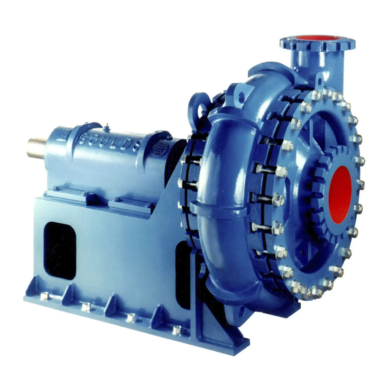
Page 15: Product Description
3.1 General description The Workhorse for the toughest services The Model 5500 severe duty slurry pumps are engineered and manufactured for dependable perform- ance and long life. Tested under punishing conditions, these heavy duty pumps stay the course and keep working efficiently. - Page 16 Figure 3: Nameplate on pump casing using metric units Table 3: Explanation of nameplate on the pump casing Nameplate field Explanation Serial number of the pump MODEL Pump model SIZE Size of the pump Model 5500 Installation, Operation, and Maintenance Manual...
- Page 17 Rated pump head, in m MAT'L. Material of which the pump is constructed IMP. DIA. Impeller diameter, in inches CONT./ITEM NO. Customer contract or item number MAX. DIA. Maximum impeller diameter, in inches Model 5500 Installation, Operation, and Maintenance Manual...
-
Page 18: Installation
4.1.2 Foundation requirements Requirements • Provide a flat, substantial concrete foundation in order to prevent strain and distortion when you tighten the foundation bolts. Model 5500 Installation, Operation, and Maintenance Manual... -
Page 19: Suction And Discharge Pipe
Arrange the belts so that both the top and bottom spans have about the same sag. Apply tension to the belts by increasing the center distance until the belts are snug. Model 5500 Installation, Operation, and Maintenance Manual... -
Page 20: Pump-To-Drive Alignment
Proper alignment is the responsibility of the installer and the user of the unit. Check the pump- to-driver alignment before you operate the unit. Failure to do so can result in equipment dam- age or decreased performance. Model 5500 Installation, Operation, and Maintenance Manual... - Page 21 (Y). Check setting of indicators by rotating coupling half X to ensure indicators stay in contact with cou- pling half Y but do not bottom out. Adjust indicators accordingly. Figure 6: Dial indicators Model 5500 Installation, Operation, and Maintenance Manual...
- Page 22 • Remove shims in order to lower the feet of the driver at the shaft end. • Add shims in order to raise the feet of the driver at the other end. Model 5500 Installation, Operation, and Maintenance Manual...
- Page 23 Negative The pump coupling half (X) is lower than the driver coupling half (Y). Remove shims of a thickness equal to half of the indicator reading value under each driver foot. Model 5500 Installation, Operation, and Maintenance Manual...
- Page 24 Make sure to slide the driver evenly. Failure to do so can negatively affect horizontal angular correction. Figure 10: Horizontal correction of the motor Repeat the previous steps until the permitted reading value is achieved. The permitted value is 0.10 mm | 0.004 in. or less. Model 5500 Installation, Operation, and Maintenance Manual...
- Page 25 4.1 Pre-installation 4.1.5.10 Seal the shaft with a packed stuffing box Goulds Model 5500 pumps are properly packed at the factory. The packing gland is set finger-tight and may require adjustment during start-up. Refer to 5.5 Adjust the stuffing box on page 24 for stuffing box adjustment.
-
Page 26: Commissioning, Startup, Operation, And Shutdown
The pump operates at optimal efficiency for long equipment life and low energy consumption. 5.5 Adjust the stuffing box If packing is used, then adjust the stuffing box during the first few hours of operation. Model 5500 Installation, Operation, and Maintenance Manual... -
Page 27: Shaft-Sealing Options
In most cases, the manufacturer seals the shaft before shipping the pump. If your pump does not have a sealed shaft, see the Shaft-seal maintenance section in the Maintenance chapter. This model uses these types of shaft seals: • Cartridge mechanical seal Model 5500 Installation, Operation, and Maintenance Manual... -
Page 28: Maintenance
Use of oil with extreme pressure additive is optional. The viscosity of the oil should be 150 SSU at the operating temperature to prevent accelerated bearing wear. Table 6: Acceptable oil Operating Temperature Gear Oil Below 71°C | 160°F SAE40 Below 82°C | 180°F SAE 50 or 90 Model 5500 Installation, Operation, and Maintenance Manual... -
Page 29: Prepare The Stuffing Box Connection
This graphic shows the proper number of rings of packing required to yield the correct locations for the lantern ring and gland. Table 7: Flush water requirements Frame Sleeve O.D. (W) Weep GPM (F) Full GPM 2.50 3.75 5.00 6.25 8.00 Model 5500 Installation, Operation, and Maintenance Manual... -
Page 30: Set The Impeller Adjustment
(1/4 turn on impeller adjusting nut) or until impeller turns freely. Lock adjustment screw (370D) in place and secure bearing housing using the bearing housing clamps (402) and bearing housing locking screws (370C). Rotate shaft to insure all parts turn freely. Model 5500 Installation, Operation, and Maintenance Manual... -
Page 31: Lubricate The End Cover Seals
Turn the shaft from the drive end counterclockwise to loosen the impeller from the shaft. A special tool is available from Goulds Pumps, Inc. to turn the shaft. The impeller must be supported before the impeller is completely unscrewed. A special tool to hold the impeller is also available from Goulds Pumps Inc. - Page 32 20. Slide shaft sleeve (126) from shaft (122). Sleeve has a female threaded end to engage with a standard pipe thread. A sleeve puller tool is available from Goulds Pumps, Inc. A pipe nipple of the correct size can also be screwed in to the sleeve end to provide an easy way to attache and pull the sleeve from the shaft.
-
Page 33: Remove The Suction Cover
(114), if pump is so equipped, and slide out of the way of the bearing puller if necessary. To remove outboard bearing (112), straighten tang in lockwasher (382A) and remove outboard bearing locknut (136) and keyed washer (140B). A keyed washer is not required on the B3 frame. Model 5500 Installation, Operation, and Maintenance Manual... -
Page 34: Guidelines For Parts Inspection And Replacement
Press outboard bearing (112) onto shaft (122). NOTICE: When bearings are heated for installation on the shaft, the temperature should not exceed 121°C | 250°F. Do not use a torch or open flame on the bearings. Model 5500 Installation, Operation, and Maintenance Manual... -
Page 35: Reassemble The Pump
A tool to help maintain alignment is available from Goulds Pumps, lnc. For the B5 frame, position hole in inboard bearing outer race so that it will engage properly with the inboard bearing locking screw (136A). The spherical design of the inboard bearing requires that it must be supported to maintain alignment with the shaft centerline. - Page 36 Figure 17: Tighten bolts 20. Wrench tighten bolts repeatedly using the criss-cross pattern until the torque value listed in follow- ing table is reached. Table 10: 5500 Casing Bolt Torque Values *Lubricate threads before tightening* O-Ring (New Design) Gasket (Old Design)
- Page 37 4.1.5 Pump-to-drive alignment on page 28. Follow procedures listed under 5.1 Lubricate the bearings with oil on page 24 for proper lubrication requirements. Be sure to add oil to the bearing housing prior to running the pump. Model 5500 Installation, Operation, and Maintenance Manual...
-
Page 38: Troubleshooting
The baseplate is not Determine which corners of the baseplate are leveled properly and is high or low. probably twisted. Remove or add shims at the appropriate cor- ners. Realign the pump and driver. Model 5500 Installation, Operation, and Maintenance Manual... - Page 39 (angu- leveled properly and is be raised or lowered. lar or parallel). probably bowed. Level screws equally at the center of the base- plate. Realign the pump and driver. Model 5500 Installation, Operation, and Maintenance Manual...
-
Page 40: Parts Listings And Cross-Sectionals
8 Parts Listings and Cross-Sectionals 8 Parts Listings and Cross-Sectionals 8.1 Assembly drawings (exploded views) Model 5500 Installation, Operation, and Maintenance Manual... - Page 41 370C BEARING HOUSING LOCKING SCREW 370D IMPELLER ADJUSTING SCREW 370H STUDS (STUFFING BOX-FRAME) 370N HEX CAP SCREWS (OUTBOARD END COVER) 370P HEX CAP SCREWS (INBOARD END COVER) 382A OUTBOARD BEARING LOCKWASHER DRIVE KEY Model 5500 Installation, Operation, and Maintenance Manual...
- Page 42 8.1 Assembly drawings (exploded views) Item Description BEARING HOUSING CLAMP SUCTION COVER CLAMP HEX SOCKET CAP SCREW O-RING (OUTBOARD END COVER) GASKET (EXPELLER - IMPELLER) Model 5500 Installation, Operation, and Maintenance Manual...
- Page 43 Visit our website for the latest version of this document and more information: http://www.gouldspumps.com Goulds Pumps Inc. 240 Fall Street Seneca Falls, NY 13148 Form IOM.5500.en-US.2020-02 ©2020 ITT Corporation The original instruction is in English. All non-English instructions are translations of the original instruction.
Need help?
Do you have a question about the 5500 and is the answer not in the manual?
Questions and answers