Table of Contents
Advertisement
Quick Links
Advertisement
Table of Contents

Related Manuals for Goulds Pumps 3420


Summary of Contents for Goulds Pumps 3420
- Page 1 Installation, Operation, and Maintenance Manual Model 3420...
-
Page 3: Table Of Contents
Perform complete alignment for a vertical correction ............25 Perform complete alignment for a horizontal correction ............. 26 Grout the baseplate ......................26 Piping checklists ........................27 General piping checklist ..................... 27 Suction-piping checklist ...................... 28 Final piping checklist ......................29 Model 3420 Installation, Operation, and Maintenance Manual... - Page 4 Parting gasket inspection and replacement ................ 69 Replace the impeller wear rings ..................70 Reassembly .......................... 71 Install the impeller ....................... 71 Bearing housing and bearings installation ................72 Install the rotating element ....................75 Model 3420 Installation, Operation, and Maintenance Manual...
- Page 5 LDS group parts list ......................103 XL and XXL group parts list ....................104 Construction details ......................106 Impeller description ......................108 Cross-sectional drawings ....................110 Other Relevant Documentation or Manuals ..............116 Model 3420 Installation, Operation, and Maintenance Manual...
-
Page 6: Introduction And Safety
ITT representative. Always specify the exact product type and identification code when requesting technical information or spare parts. Model 3420 Installation, Operation, and Maintenance Manual... -
Page 7: Safety
It is extremely important that you read, understand, and follow the safety messages and regulations carefully before handling the product. They are published to help prevent these hazards: • Personal accidents and health problems • Damage to the product • Product malfunction Model 3420 Installation, Operation, and Maintenance Manual... -
Page 8: Environmental Safety
• Handle and dispose of the processed liquid in compliance with applicable environmental regulations. • Clean up all spills in accordance with safety and environmental procedures. • Report all environmental emissions to the appropriate authorities. Model 3420 Installation, Operation, and Maintenance Manual... -
Page 9: User Safety
• Make sure that there are no poisonous gases within the work area. • Make sure that you have quick access to a first-aid kit. • Disconnect and lock out power before servicing. Model 3420 Installation, Operation, and Maintenance Manual... -
Page 10: Ex-Approved Products
The relevance of the ATEX requirements is not limited to Europe. You can apply these guidelines to equipment installed in any potentially explosive atmosphere. Model 3420 Installation, Operation, and Maintenance Manual... -
Page 11: Monitoring Equipment
• Material damages • Economic losses Warranty claim ITT products are high-quality products with expected reliable operation and long life. However, should the need arise for a warranty claim, then contact your ITT representative. Model 3420 Installation, Operation, and Maintenance Manual... -
Page 12: Transportation And Storage
Support the pump with a sling under the two bearing housings and a sling under the motor end of the baseplate. Pump, base, and motor Attach slings to the baseplate lifting lugs. Use a spreader bar so that the pump is not damaged. Model 3420 Installation, Operation, and Maintenance Manual... -
Page 13: Bare Pump
Pump, base, and motor Storage guidelines Pump storage requirements Storage requirements depend on the amount of time that you store the unit. The normal packaging is designed only to protect the unit during shipping. Model 3420 Installation, Operation, and Maintenance Manual... - Page 14 You can purchase long-term storage treatment with the initial unit order or you can purchase it and apply it after the units are already in the field. Contact your local ITT sales representative. Model 3420 Installation, Operation, and Maintenance Manual...
-
Page 15: Product Description
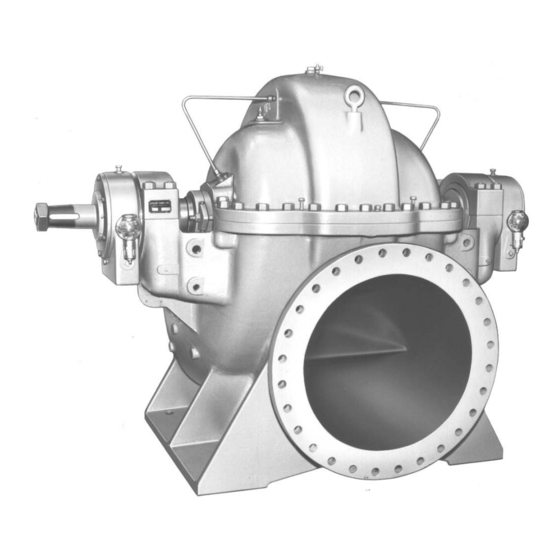
Product Description Product Description General Description Product description Model 3420 is a horizontal, centrifugal pump with these characteristics: • Single stage • Double suction • Enclosed impeller Model 3420 uses English dimensions. Casing • The casing is horizontally split. The upper and lower halves are held together with studs and nuts or capscrews. -
Page 16: Pump Group Definitions
Nameplate information Important information for ordering Every pump has nameplates that provide information about the pump. The nameplates are located on the casing and the bearing frame. Model 3420 Installation, Operation, and Maintenance Manual... - Page 17 Rated pump speed, revolutions per minute SER. NO. Serial number of the pump MAX. DSGN. PSI @ 100F Maximum pressure at 100ºF according to the pump design Nameplate on the pump casing using metric units Model 3420 Installation, Operation, and Maintenance Manual...
- Page 18 °F (°C) temperature in °F (°C) 842 (450) 700 (372) 572 (300) 530 (277) 392 (200) 350 (177) 275 (135) 235 (113) 212 (100) Option not available 185 (85) Option not available Model 3420 Installation, Operation, and Maintenance Manual...
- Page 19 NOTICE: Make sure that the code classifications on the pump are compatible with the specific environment in which you plan to install the equipment. If they are not compatible, do not operate the equipment and contact your ITT representative before you proceed. Model 3420 Installation, Operation, and Maintenance Manual...
-
Page 20: Installation
Make sure there is a suitable power source available If the pump is motor-driven, then the electrical for the pump driver. characteristics of the power source should be identical to those shown on motor data plate. Model 3420 Installation, Operation, and Maintenance Manual... -
Page 21: Foundation Requirements
• The foundation must be poured to within 1.905 – 3.81 cm | 0.75 – 1.5 in. of the finished height. Sleeve-type bolts Item Description Baseplate Shims Foundation Sleeve Bolt Figure 1: Sleeve type bolts J-type bolts Item Description Baseplate Shims or wedges Foundation Bolt Figure 2: J-type bolts Model 3420 Installation, Operation, and Maintenance Manual... -
Page 22: Baseplate-Mounting Procedures
4. Coat the exposed portion of the anchor bolts with a non-bonding compound such as paste wax in order to prevent the grout from adhering to the anchor bolts. Do not use oils or liquid wax. Model 3420 Installation, Operation, and Maintenance Manual... -
Page 23: Install And Level The Baseplate
1. Mount and fasten the pump on the baseplate. Use applicable bolts. 2. Mount the driver on the baseplate. Use applicable bolts and hand tighten. 3. Install the coupling. See the installation instructions from the coupling manufacturer. Model 3420 Installation, Operation, and Maintenance Manual... -
Page 24: Pump-To-Driver Alignment
When dial indicators are used to check the final alignment, the pump and drive unit are correctly aligned when the total indicator runout is a maximum of 0.05 mm | 0.002 in. at operating temperature. Model 3420 Installation, Operation, and Maintenance Manual... -
Page 25: Alignment Measurement Guidelines
This indicator is used to measure angular misalignment. 2. Rotate the pump coupling half (X) in order to check that the indicators are in contact with the driver coupling half (Y) but do not bottom out. Model 3420 Installation, Operation, and Maintenance Manual... -
Page 26: Perform Angular Alignment For A Vertical Correction
0.05 mm | 0.002 in. as measured at four points 90° apart at the operating temperature. 1. Set the parallel alignment indicator (P) to zero at the top-center position (12 o’clock) of the driver coupling half (Y). Model 3420 Installation, Operation, and Maintenance Manual... -
Page 27: Perform Parallel Alignment For A Horizontal Correction
2. Rotate the indicators to the bottom-center position (6 o’clock). 3. Record the indicator readings. 4. Make corrections according to the separate instructions for angular and parallel alignment until you obtain the permitted reading values. Model 3420 Installation, Operation, and Maintenance Manual... -
Page 28: Perform Complete Alignment For A Horizontal Correction
• Puddle with a vibrator. • Pump the grout into place. 5. Allow the grout to set. Item Description Baseplate Shims or wedges Grout Foundation Sleeve Bolt Figure 3: Pour grout into baseplate Model 3420 Installation, Operation, and Maintenance Manual... -
Page 29: Piping Checklists
Flange loads from the piping system, including those from the thermal expansion of the piping, must not exceed the limits of the pump. Casing deformation can result in contact with rotating parts, which can result in excess heat generation, sparks, and premature failure. Model 3420 Installation, Operation, and Maintenance Manual... -
Page 30: Suction-Piping Checklist
Check that the eccentric reducer at the suction flange of the pump has the following properties: • Sloping side down • Horizontal side at the top Model 3420 Installation, Operation, and Maintenance Manual... -
Page 31: Final Piping Checklist
Check that the shaft rotates smoothly. Rotate the shaft by hand. Make sure there is no rubbing that can lead to excess heat generation or sparks. Re-check the alignment to make sure If pipe strain exists, then correct the piping. that pipe strain has not caused any misalignment. Model 3420 Installation, Operation, and Maintenance Manual... -
Page 32: Commissioning, Startup, Operation, And Shutdown
• Flush and clean the system thoroughly to remove dirt or debris in the pipe system in order to prevent premature failure at initial startup. • Bring variable-speed drivers to the rated speed as quickly as possible. Model 3420 Installation, Operation, and Maintenance Manual... -
Page 33: Check The Rotation - Frame Mounted
• Running a pump without safety devices exposes operators to risk of serious personal injury or death. Never operate a unit unless appropriate safety devices (guards, etc.) are properly installed. Model 3420 Installation, Operation, and Maintenance Manual... -
Page 34: Install The Coupling Guard
Replace the coupling hub (if removed) and the spacer portion of the coupling. Refer to the instructions from the coupling manufacturer for assistance. Complete any coupling adjustments before you proceed with the coupling guard assembly. Model 3420 Installation, Operation, and Maintenance Manual... - Page 35 Item Description Pump half of the coupling guard Annular groove Deflector fan guard Driver Figure 6: Coupling guard Item Description Coupling guard half Annular groove Pump end plate Driver Figure 7: Coupling guard Model 3420 Installation, Operation, and Maintenance Manual...
- Page 36 4. Place a second washer over the exposed end of the bolt. 5. Thread a nut onto the exposed end of the bolt and tighten firmly. This figure shows the proper sequence of components: Item Description Washer Bolt This figure shows an assembled unit: Model 3420 Installation, Operation, and Maintenance Manual...
- Page 37 6. Slightly spread the opening of the remaining coupling guard half and place it over the installed coupling guard half so that the annular groove in the remaining coupling guard half faces the driver. Item Description Annular groove Coupling guard half Driver Figure 10: Coupling guard Model 3420 Installation, Operation, and Maintenance Manual...
- Page 38 Slide to fit Figure 12: Slide to fit 10. Repeat Steps (page 34) through #InstallTheCouplingGuard/ThreadBolt (page ) for the center slots in the coupling guard. 11. Firmly tighten all nuts on the guard assembly. Model 3420 Installation, Operation, and Maintenance Manual...
-
Page 39: Bearing Lubrication
180°F, refer to the table for temperature requirements. Temperature Oil requirement Bearing temperatures exceed 82°C | 180°F Use ISO viscosity grade 100. Bearing temperatures are generally about 11°C | 20°F higher than bear- ing-housing outer surface temperatures. Model 3420 Installation, Operation, and Maintenance Manual... -
Page 40: Acceptable Oil For Lubricating Bearings
Place your thumb over the reservoir spout. Invert and insert the spout into the internal threaded boss on the main body. e) Tighten reservoir. Do not over-tighten. Verify that proper oil level is maintained per the following diagram. Oiler bottle needs to be filled several times. Model 3420 Installation, Operation, and Maintenance Manual... -
Page 41: Lubricate The Bearings With Pure Or Purge-Oil Mist (Optional)
-15°C to 110°C | 5°F to 230°F Use a lithium-based mineral-oil grease with a con- sistency of NLGI 2. Exceed 177°C | 350°F Use a high-temperature grease. Mineral-oil greases should have oxidation stabilizers and a consistency of NGLI 3. Model 3420 Installation, Operation, and Maintenance Manual... -
Page 42: Regrease The Grease-Lubricated Bearings
15 psi greater than the seal chamber pressure. The injection rate must be 2 to 8 lpm | 0.5 to 2 gpm. Other You can use other methods that employ multiple gland or seal chamber connections. Refer to the mechanical seal reference drawing and piping diagrams. Model 3420 Installation, Operation, and Maintenance Manual... -
Page 43: Packed Stuffing Box Option
1. Carefully clean the stuffing-box bore . 2. Twist the packing enough to get it around the shaft. Figure 15: Packing rings and lantern rings Model 3420 Installation, Operation, and Maintenance Manual... -
Page 44: Pump Priming
Prime with the suction supply above the pump When the pump is installed as this figure shows, the pump primes itself: Model 3420 Installation, Operation, and Maintenance Manual... -
Page 45: Prime With The Suction Supply Below The Pump
Method Parts list Method A: Outside supply 1. From outside supply 2. Shutoff valve 3. Vent plug 4. Discharge gate valve 5. Foot valve Model 3420 Installation, Operation, and Maintenance Manual... - Page 46 4. For method B, close the valve in the priming line and shut off the priming pump. 5. For methods A and C, replace the vent plugs or close the vent valves, and then close the valve in the priming supply line. Model 3420 Installation, Operation, and Maintenance Manual...
-
Page 47: Prime With An Ejector
Risk of equipment damage on pure or purge-oil mist-lubricated units. Remove the viewing port plugs to verify that oil mist is flowing properly. Reinstall the plugs after confirming. Before you start the pump, you must perform these tasks: • Open the suction valve. Model 3420 Installation, Operation, and Maintenance Manual... -
Page 48: Pump Operation Precautions
Do not expose an idle pump to freezing conditions. Drain all liquid that is inside the pump and any auxiliary equipment. Failure to do so can cause liquid to freeze and damage the pump. Model 3420 Installation, Operation, and Maintenance Manual... -
Page 49: Shut Down The Pump
Proper personal protective equipment should be worn. Pumpage must be handled and disposed of in conformance with applicable environmental regulations. 1. Slowly close the discharge valve. 2. Shut down and lock out the driver to prevent accidental rotation. Model 3420 Installation, Operation, and Maintenance Manual... -
Page 50: Make The Final Alignment Of The Pump And Driver
See Remove the coupling guard in the Maintenance chapter. 4. Check the alignment while the unit is still hot. See Pump-to-driver alignment in the Installation chapter. 5. Reinstall the coupling guard. 6. Restart the pump and driver. Model 3420 Installation, Operation, and Maintenance Manual... -
Page 51: Maintenance
• Check the pump power. If the pump performance does not satisfy your process requirements, and the process requirements have not changed, then perform these steps: 1. Disassemble the pump. 2. Inspect it. Model 3420 Installation, Operation, and Maintenance Manual... -
Page 52: Bearing Maintenance
Do not expose an idle pump to freezing conditions. Drain all liquid that is inside the pump and any auxiliary equipment. Failure to do so can cause liquid to freeze and damage the pump. Model 3420 Installation, Operation, and Maintenance Manual... - Page 53 During operation, bullseye sight gives a false oil level reading. Shown is general schematic. Oil level is below outer race of bearing. 1. Plug 2. Reservoir 3. Main body Figure 17: Checking oil level Model 3420 Installation, Operation, and Maintenance Manual...
-
Page 54: Lubricating-Grease Requirements
Remove the ball bearings 1. Square the puller bar with the end of the shaft. The bar must be square at all times in order to keep even pressure on the outer circumference of the bearing. Model 3420 Installation, Operation, and Maintenance Manual... -
Page 55: Remove The Roller Bearings
2. Slide the adapter sleeves and bearings off of the shaft and protect them from contamina- tion. 3. Unscrew the adapter removal nut and store it for future use. Mechanical-seal maintenance WARNING: The mechanical seal used in an Ex-classified environment must be properly certified. Model 3420 Installation, Operation, and Maintenance Manual... -
Page 56: Packed Stuffing-Box Maintenance
Never over-tighten packing to the point where less than one drop per second is observed. Over-tightening can cause excessive wear and power consumption during operation. If you cannot tighten the packing to obtain less than the specified leakage rate, then replace the packing. Model 3420 Installation, Operation, and Maintenance Manual... -
Page 57: Disassembly
Remove the gland nuts (355) and slide the glands (107) away from the stuffing boxes. Conventional me- Remove the gland nuts (355) and slide the gland and the stationary seat chanical seal away from the seal chamber. Model 3420 Installation, Operation, and Maintenance Manual... -
Page 58: Remove The Coupling Guard
Slightly spread the bottom apart. b) Lift upwards. Item Description Annular groove Coupling guard half Driver 5. Remove the remaining nut, bolt, and washers from the pump half of the coupling guard. Model 3420 Installation, Operation, and Maintenance Manual... -
Page 59: Remove The Casing
4. Remove the upper half of the casing evenly using the lifting lugs. Make sure adequate clearance is available in order to remove the upper half. Use care in order to prevent any tears to the casing gasket. Model 3420 Installation, Operation, and Maintenance Manual... - Page 60 18 x 20-24 38 (965) 24 x 30-32 45 (1143) 30 x 30-31 51 (1288) 30 x 30-38 53 (1353) 20 x 30-42 70 (1778) 30 x 36-42 62 (1575) 36x42-52 76 (1930) Model 3420 Installation, Operation, and Maintenance Manual...
-
Page 61: Bearing Housing And Bearings Removal
Make sure all stationary parts of the rotating element are loose before you remove the rotating element. c) Rotate the casing wearing rings (127) 180° in order to disengage the tongue and groove locks. Model 3420 Installation, Operation, and Maintenance Manual... - Page 62 (page 52) for more information. Save the bearings for inspection. 11. Slide the bearing end covers (109) and labyrinth seals (333A) off of the shaft. Press the labyrinth seals out of the end covers from the inside using a properly-sized arbor. Model 3420 Installation, Operation, and Maintenance Manual...
- Page 63 4. Rotate the casing wearing rings (127), stuffing box bushings (125), and the bearing housings (134A) 180° to disengage the tongue and groove locks. 5. Remove the element and place it on padded supports. 6. Slide the casing rings off the rotating element. Model 3420 Installation, Operation, and Maintenance Manual...
- Page 64 Remove the bearing housing and bearings for the L group Table 6: L group - 24 x 30-32 Figure 27: Ring oil, radial Figure 26: Ring oil, thrust Figure 29: Grease, radial Figure 28: Grease, thrust Model 3420 Installation, Operation, and Maintenance Manual...
- Page 65 • For oil lubrication, loosen the setscrews (363B) in the oil throwers (248) and slide the oil throwers off of the shaft. • For grease lubrication, slide the deflectors (123) off of the shaft. Model 3420 Installation, Operation, and Maintenance Manual...
- Page 66 Table 7: LDS and XL groups - 30 x 30-31, 30 x 30-38, 30 x 36-42, 36 x 42-52 Figure 31: LDS ring oil, radial Figure 30: LDS ring oil, thrust Figure 32: LDS grease, thrust Figure 33: LDS grease, radial Model 3420 Installation, Operation, and Maintenance Manual...
- Page 67 3. Place the sling in position and remove the rotating element: a) Adjust the sling tension in order to take weight off of the rotating element. Model 3420 Installation, Operation, and Maintenance Manual...
-
Page 68: Disassemble The Rotating Element
5. Carefully slide the sleeves (126) off of the shaft. Discard the impeller O-rings (412A). If the pump has conventional mechanical seals, then the stuffing box bushings and the rotary elements of the mechanical seals are still mounted to the sleeves. Model 3420 Installation, Operation, and Maintenance Manual... -
Page 69: Pre-Assembly Inspections
Gaskets, O-rings, and seats replacement WARNING: Risk of death or serious injury. Leaking fluid can cause fire and/or burns. Replace all gaskets and O-rings at each overhaul or disassembly. Model 3420 Installation, Operation, and Maintenance Manual... -
Page 70: Bearings Inspection
• Make sure that the O-ring groove is in good condition. • Check the diametrical clearance between the sleeve and the stuffing box bushing. Replace the sleeve and/or stuffing box if the clearance is more than 0.030 in. (0.762 mm). Model 3420 Installation, Operation, and Maintenance Manual... -
Page 71: Shaft Replacement Guidelines
For pumps with mechanical seals, cut the gasket approximately 0.25 in (6.35 mm) long at the face of the stuffing box. Then trim the excess to a perfect fit after the pump casing is assembled. Model 3420 Installation, Operation, and Maintenance Manual... -
Page 72: Replace The Impeller Wear Rings
Replacement impeller wear rings are supplied 0.020 - 0.030 in. (0.508 - 0.762 mm) oversized and must be turned to size after you mount them on the impeller. SX and MX size rings are supplied turned to the finished diameter. Model 3420 Installation, Operation, and Maintenance Manual... -
Page 73: Reassembly
2. Carefully slide the seal glands with the stationary seats and the gland gaskets on the shaft. Cartridge mechanical Carefully slide the cartridge unit on the sleeve. seal Model 3420 Installation, Operation, and Maintenance Manual... -
Page 74: Bearing Housing And Bearings Installation
Slide both oil throwers (248) on the shaft (122). Grease Slide both deflectors (248) on the shaft (122). 2. For grease-lubricated pumps, install the grease seals (333) in the bearing housings (134A) using a properly-sized arbor. Model 3420 Installation, Operation, and Maintenance Manual... - Page 75 Bolt the oil ring housings (515 and 515A) to the bearing housings (134 and 134A) using capscrews (371T). b) Place the oil rings (114) in the grooves on the oil ring sleeve. Model 3420 Installation, Operation, and Maintenance Manual...
- Page 76 Verify that the minimum clearance is not less than the value given in the table. Rotate the bearing through 90° increments and verify the clearance in a few positions. 7. Bend a tang of the lockwasher into a locknut groove. Model 3420 Installation, Operation, and Maintenance Manual...
-
Page 77: Install The Rotating Element
1. Bolt the thrust end of the bearing housing to the casing using the bearing housing-to-casing capscrews (372U). 2. Tighten the capscrews to the torque values shown in the Bolt torque values table. Model 3420 Installation, Operation, and Maintenance Manual... - Page 78 15. For grease-lubricated pumps, slide the deflectors (123) to within 0.0312 in. (0.792 mm) of the bearing end covers or adapters. 16. Tighten the setscrews (364). 17. Repack the stuffing box and replace the gland assembly. 18. Install all auxiliary piping. Model 3420 Installation, Operation, and Maintenance Manual...
-
Page 79: Assembly References
D02282A 58954 0.018 28.58 0.009 14.29 20x24-28G D02283A 58955 0.018 28.58 0.009 14.29 20x24-28H D01539A 58719 0.018 28.58 0.009 14.29 D02299A 58976 0.018 28.58 0.009 14.29 20x24-28N D02300A 58977 0.018 28.58 0.009 14.29 Model 3420 Installation, Operation, and Maintenance Manual... - Page 80 D02287A 58959 0.024 38.10 0.012 19.05 267-57 57039 0.0304 48.26 0.0152 24.13 30x36-42H 272-80 57039 0.0304 48.26 0.0152 24.13 30x36-42N D07751A 69830 0.0304 48.26 0.0152 24.13 20x30-42 D11284A IE994 0.0304 48.26 0.0152 24.13 Model 3420 Installation, Operation, and Maintenance Manual...
- Page 81 139.60 111.15 111.07 0.0762 24x30-32 3420/ 166.42/ 164.90/ 1.52/1.70 155.58/ 155.55/ 0.0254/ 0.397 166.55 164.85 155.60 155.52 0.0762 30x30-31 3420/ 190.02/ 190.50/ 174.63/ 174.60/ 0.0254/ 1.52/1.70 0.397 192.15 190.45 174.65 174.57 0.0762 30x30-38 Model 3420 Installation, Operation, and Maintenance Manual...
- Page 82 19.528 19.548 0.020 18.595 18.615 0.020 Iron and 0.38 8° bronze 19.525 19.551 0.026 18.592 18.618 0.026 18x20-30 19.528 19.558 0.030 18.595 18.625 0.030 Steel 0.38 8° 19.525 19.561 0.036 18.592 18.628 0.036 Model 3420 Installation, Operation, and Maintenance Manual...
- Page 83 15.984 16.000 0.016 15.984 16.000 0.016 Iron and 0.38 8° bronze 15.981 16.003 0.022 15.981 16.003 0.022 18x20- 15.974 16.000 0.026 15.984 16.000 0.026 Steel 0.38 8° 15.971 16.003 0.032 15.971 16.003 0.032 Model 3420 Installation, Operation, and Maintenance Manual...
- Page 84 24.974 25.000 0.026 24.974 25.000 0.026 Iron and 0.38 8° bronze 24.970 25.004 0.034 24.970 25.004 0.034 30x30- 24.964 25.000 0.036 24.964 25.000 0.036 Steel 0.38 8° 24.960 25.004 0.044 24.960 25.004 0.044 Model 3420 Installation, Operation, and Maintenance Manual...
- Page 85 354.84 355.17 0.33 354.84 355.17 0.33 Iron and 12.70 8° bronze 354.79 355.22 0.43 354.84 355.17 0.33 16x18- 354.84 355.42 0.58 354.84 355.42 0.58 Steel 12.70 8° 354.79 355.47 0.69 354.79 355.47 0.69 Model 3420 Installation, Operation, and Maintenance Manual...
- Page 86 469.90 0.51 Iron and 6 and 9.65 8° bronze 469.32 469.98 0.66 469.32 469.98 0.66 20x24-28 469.14 469.90 0.76 469.14 469.90 0.76 6 and Steel 9.65 8° 469.32 470.66 0.91 469.32 469.98 0.91 Model 3420 Installation, Operation, and Maintenance Manual...
- Page 87 557.76 558.32 0.56 557.76 558.32 0.56 Iron and 12.70 8° bronze 557.68 558.39 0.71 557.68 558.39 0.71 24x30- 557.76 558.57 0.81 557.76 558.57 0.81 Steel 12.70 8° 557.68 558.65 0.97 557.68 558.65 0.97 Model 3420 Installation, Operation, and Maintenance Manual...
- Page 88 30x36- 710.39 711.20 0.81 710.39 711.20 0.81 Steel 9.65 8° 710.31 711.28 0.97 710.31 711.28 0.97 529.56 530.30 0.81 Iron and bronze 529.49 530.20 0.64 20x30-42 529.39 530.30 0.97 Steel 529.34 530.20 0.81 Model 3420 Installation, Operation, and Maintenance Manual...
- Page 89 -0.0006 9.0575 9.0539 -0.0036 30x30-31 22228 22228 9.8431 9.8425 -0.0006 30x30-38 9.8449 9.8413 -0.0036 30x36-42 22230 22230 10.6306 10.6299 -0.0007 20x30-42 10.6326 10.6285 -0.0041 36x42-52 22240 22240 14.1762 14.1716 -0.0007 14.1739 14.1732 -0.0046 Model 3420 Installation, Operation, and Maintenance Manual...
- Page 90 250 ft-lb (339 Nm) 220 ft-lb (298 Nm) 145 ft-lb (197 Nm) 640 ft-lb (868 Nm) 425 ft-lb (576 Nm) 440 ft-lb (597 Nm) 295 ft-lb (400 Nm) 1275 ft-lb (1729 Nm) 850 ft-lb (1153 Nm) Model 3420 Installation, Operation, and Maintenance Manual...
- Page 91 12x14-15 16x18-17H 16x18-30 18x20-24 18x20-30 20x24-24 24x24-28 20x24-30 r in in. Wet Dry Wet Dry (mm) 10.50 — — — — — — — — — — — — — — (266.70) (11) Model 3420 Installation, Operation, and Maintenance Manual...
- Page 92 — — — — — — (635.00) (390) (423) (377) (397) (338) (420) (297) (324) 25.50 — — — — — — — — (647.70) (415) (447) (393) (418) (359) (441) (317) (344) Model 3420 Installation, Operation, and Maintenance Manual...
- Page 93 1,355 1,900 — — — — (812.80) (1,144) (1,348) (840) (1,051) (1,627) (2,339) (1,837) (2,576) 32.50 — — 1,300 1,810 1,415 1,960 — — — — (825.50) (889) (1,112) (1,763) (2,454) (1,918) (2,657) Model 3420 Installation, Operation, and Maintenance Manual...
- Page 94 (16,405) 51.00 — — — — — — — — — — 11,000 12,700 (69.15) (14,914) (17,219) 52.00 — — — — — — — — — — 11,500 13,200 (70.50) (15,592) (17,897) Model 3420 Installation, Operation, and Maintenance Manual...
- Page 95 30x30-38 3162 1 D02259A Maximum — — — 19,218 15,970 D02257A Minimum — — — 19,218 15,970 30x36-42G 3246 D02286A Maximum — — — — 18,359 D02287A Minimum — — — — 18,359 Model 3420 Installation, Operation, and Maintenance Manual...
- Page 96 — — 1,180 — — — — — — — — — — 0.67 0.88 — — — 0.54 0.71 0.71 0.80 — 0.45 0.59 0.59 0.66 0.75 0.39 0.50 0.50 0.57 0.64 Model 3420 Installation, Operation, and Maintenance Manual...
- Page 97 — — 1,180 — — — — — — — — — — 1.62 1.58 — — — 0.97 1.27 1.27 1.43 — 0.81 1.06 1.06 1.19 1.34 0.69 0.90 0.90 1.02 1.15 Model 3420 Installation, Operation, and Maintenance Manual...
-
Page 98: Troubleshooting
The suction or discharge piping is not Anchor the piping according the recom- anchored or properly supported. mendations in the Hydraulic Institute Standards Manual. The pump is cavitating. Locate and correct the system problem. Model 3420 Installation, Operation, and Maintenance Manual... - Page 99 The packing is too tight. Readjust the packing. Replace the pack- ing if it is worn. Rotating parts are binding. Make sure that there are proper clear- ances for the internal wearing parts. Model 3420 Installation, Operation, and Maintenance Manual...
-
Page 100: Parts Listings And Cross-Sectionals
Hex capscrew, casing Steel - 2442 stud Varies Hex nut, casing stud Steel - 2442 Varies Hex capscrew, casing Steel parting 445A Pin, anti-rotation F738M Class A2-70 469G Taper pin Steel A276 Type 316 Model 3420 Installation, Operation, and Maintenance Manual... -
Page 101: M, M-Modified, And 20X24-28 Group Parts List
A276 Type 316 355B Hex nut, quench gland Steel A276 Type 316 356A Varies Stud, casing Steel - 2443 356P Stud, casing bearing cap Steel - 2210 356Q Varies Stud, casing parting Steel - 2210 Model 3420 Installation, Operation, and Maintenance Manual... -
Page 102: Standard Group Parts List (18X20-24)
Pipe nipple Grease fitting Steel Packing, gland Non-asbestos 222B Setscrew, sleeve nut A276 Type 316 222P Setscrew, deflector A276 Type 316 222Q Setscrew, grease shield A276 Type 316 Swing bolt Steel A276 Type 316 Model 3420 Installation, Operation, and Maintenance Manual... -
Page 103: L Group Parts List
109A Bearing end cover A48 Class 25B Bearing cap, grease A48 Class 30B 111A Bearing cap A48 Class 30B 113A Breather Steel Oil ring B584 C87500 Bearing end cover, A48 Class 25B grease Model 3420 Installation, Operation, and Maintenance Manual... - Page 104 371S Hex capscrew, cover-to- Steel - 2210 housing 371T Hex capscrew, housing- Steel - 2210 to-housing Bearing lockwasher Steel 388Q Hex capscrew, retainer Steel - 2210 Key, coupling (not shown) Steel Model 3420 Installation, Operation, and Maintenance Manual...
-
Page 105: Lds Group Parts List
Impeller wear ring A48 Class 25B B584 C87500 A743 CF-8M Impeller key A582 Type 303 A276 Type 316 190E Pipe nipple Grease fitting Steel Packing, gland Non-asbestos 222B Setscrew, sleeve nuts A276 Type 316 Model 3420 Installation, Operation, and Maintenance Manual... -
Page 106: Xl And Xxl Group Parts List
Bearing cap A48 Class 25B 113A Breather Steel Oil ring B584 C87500 119A Bearing end cover A48 Class 25B 119B Bearing end cover A48 Class 25B Shaft A322 GR 4340 A276 Type 316 Model 3420 Installation, Operation, and Maintenance Manual... - Page 107 Steel - 2210 425A Hex nut, casing bearing Steel - 2210 425B Varies Hex nut, casing parting Steel - 2210 469G Dowel pin, casing Steel - 2210 469L Dowel pin, end cover Steel - 2210 Model 3420 Installation, Operation, and Maintenance Manual...
-
Page 108: Construction Details
(157.48 cm) (139.70 cm) Maximum shaft HP/100 Maximum to- 175 psi 150 psi 200 psi 150 psi 200 psi tal working pressure Hydrotest 263 psi 225 psi 300 psi 225 psi 300 psi pressure Model 3420 Installation, Operation, and Maintenance Manual... - Page 109 72.50 in. (184.15 cm) 80.19 in. (203.68 76.12 in. (193.34 94.65 in. (240.41 Maximum shaft HP/100 rpm Maximum total 150 psi 125 psi 150 psi working pressure Hydrotest pres- 225 psi 188 psi 225 psi sure Model 3420 Installation, Operation, and Maintenance Manual...
-
Page 110: Impeller Description
Yes/No 265-82 56848 262-22 56828 (81.28) (16.84) (3361.28) 24x30- 32.00 6.13 460.00 Yes/No 265-84 56879 262-25 56529 32STD (81.28) (15.57) (2967.74) 24x30- 32.00 6.13 385.00 Yes/No 267-21 56884 D00013A 57618 (81.28) (15.57) (2483.87) Model 3420 Installation, Operation, and Maintenance Manual... - Page 111 894.00 Yes/No D02258A 58784 D02260A 58786 (116.84) (25.10) (5767.73) 30x42- 46.00 11.00 822.40 Yes/No D02288A 58960 D02289A 58961 (116.84) (27.94) (5305.80) 30x42- 46.00 12.75 1020.50 No/No D02295A 58971 D02296A 58972 (116.84) (32.89) (6583.86) Model 3420 Installation, Operation, and Maintenance Manual...
-
Page 112: Cross-Sectional Drawings
Parts Listings and Cross-Sectionals Cross-sectional drawings XL and XXL Model 3420 Installation, Operation, and Maintenance Manual... - Page 113 Parts Listings and Cross-Sectionals M and 20 x 24-28 Model 3420 Installation, Operation, and Maintenance Manual...
- Page 114 Parts Listings and Cross-Sectionals Model 3420 Installation, Operation, and Maintenance Manual...
- Page 115 Parts Listings and Cross-Sectionals SX and MX Model 3420 Installation, Operation, and Maintenance Manual...
- Page 116 Parts Listings and Cross-Sectionals 18x20-24 Model 3420 Installation, Operation, and Maintenance Manual...
- Page 117 Parts Listings and Cross-Sectionals Model 3420 Installation, Operation, and Maintenance Manual...
-
Page 118: Other Relevant Documentation Or Manuals
Other Relevant Documentation or Manuals Other Relevant Documentation or Manuals For additional documentation For any other relevant documentation or manuals, contact your ITT representative. Model 3420 Installation, Operation, and Maintenance Manual... - Page 120 Visit our website for the latest version of this document and more information: http://www.gouldspumps.com Goulds Pumps 240 Fall Street Seneca Falls, NY 13148 Form IOM.3420.en-US.2018-12 © 2018 ITT Corporation The original instruction is in English. All non-English instructions are translations of the original instruction.
Need help?
Do you have a question about the 3420 and is the answer not in the manual?
Questions and answers