Table of Contents
Advertisement
Quick Links
Advertisement
Table of Contents

Related Manuals for Goulds Pumps 3420


Summary of Contents for Goulds Pumps 3420
- Page 1 Installation, Operation, and Maintenance Manual Model 3420...
-
Page 3: Table Of Contents
4.4.7 Perform parallel alignment for a vertical correction............... 27 4.4.8 Perform parallel alignment for a horizontal correction..............28 4.4.9 Perform complete alignment for a vertical correction..............28 4.4.10 Perform complete alignment for a horizontal correction.............. 29 Model 3420 Installation, Operation, and Maintenance Manual... - Page 4 6.5.3 Remove the coupling guard ......................59 6.5.4 Remove the casing ........................60 6.5.5 Bearing housing and bearings removal..................62 6.5.6 Disassemble the rotating element....................68 6.6 Pre-assembly inspections ........................69 6.6.1 Replacement guidelines........................ 69 Model 3420 Installation, Operation, and Maintenance Manual...
- Page 5 8.6 XL and XXL group parts list........................116 8.7 Construction details..........................118 8.8 Impeller description ..........................121 8.9 Cross-sectional drawings ........................124 9 Other Relevant Documentation or Manuals....................130 9.1 For additional documentation ........................ 130 Model 3420 Installation, Operation, and Maintenance Manual...
-
Page 6: Introduction And Safety
ITT. If there is any uncertainty regarding the appropriate use of the equipment, please contact an ITT representative before proceeding. Model 3420 Installation, Operation, and Maintenance Manual... -
Page 7: Safety Terminology And Symbols
A practice not related to personal injury Hazard categories Hazard categories can either fall under hazard levels or let specific symbols replace the ordinary hazard level symbols. Electrical hazards are indicated by the following specific symbol: Model 3420 Installation, Operation, and Maintenance Manual... -
Page 8: Environmental Safety
Electrical installation For electrical installation recycling requirements, consult your local electric utility. 1.2.2.1 Recycling guidelines Always follow local laws and regulations regarding recycling. 1.2.3 User safety General safety rules These safety rules apply: Model 3420 Installation, Operation, and Maintenance Manual... - Page 9 Read this manual carefully before instal- ling and using the product. • Never work alone. • Always wear protective clothing and hand protection. • Stay clear of suspended loads. Model 3420 Installation, Operation, and Maintenance Manual...
-
Page 10: Ex-Approved Products
Special rules apply to installations in explosive atmospheres. • All users must know about the risks of electric current and the chemical and physical characteristics of the gas, the vapor, or both present in hazardous areas. Model 3420 Installation, Operation, and Maintenance Manual... -
Page 11: Product Approval Standards
The product is used only under the conditions described in this manual. • The monitoring equipment incorporated in the product is correctly connected and in use. • All service and repair work is done by ITT-authorized personnel. • Genuine ITT parts are used. Model 3420 Installation, Operation, and Maintenance Manual... -
Page 12: Atex Considerations And Intended Use
Maintenance manual (IOM) can cause serious personal injury or damage to the equipment. This in- cludes any modification to the equipment or use of parts not provided by ITT Goulds Pumps. If there is any question regarding the intended use of the equipment, please contact an ITT Goulds representative before proceeding. - Page 13 The code classification marked on the equipment must be in accordance with the specified area where the equipment will be installed. If it is not, do not operate the equipment and contact your ITT Goulds Pumps sales representative before proceeding. Model 3420 Installation, Operation, and Maintenance Manual...
-
Page 14: Transportation And Storage
Lifting and handling heavy equipment poses a crush hazard. Use caution during lifting and handling and wear appropriate Personal Protective Equipment (PPE, such as steel- toed shoes, gloves, etc.) at all times. Seek assistance if necessary. • Do not attach sling ropes to shaft ends. Model 3420 Installation, Operation, and Maintenance Manual... - Page 15 Figure 3: The proper lifting method for a vertical pump mounted on a half pedestal 30° max Nylon sling, chain, or wire rope Figure 4: The proper lifting method for a vertical pump mounted on a full pedestal Model 3420 Installation, Operation, and Maintenance Manual...
-
Page 16: Storage Guidelines
Table 2: Situations when the pump is or is not frostproof Situation Condition Operating The pump is frostproof. Immersed in a liquid The pump is frostproof. Lifted out of a liquid into a temperature below freezing The impeller might freeze. Model 3420 Installation, Operation, and Maintenance Manual... -
Page 17: Product Description
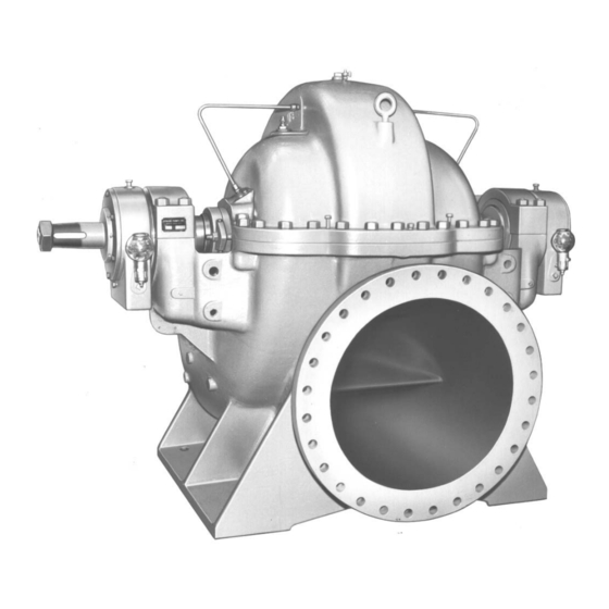
3 Product Description 3 Product Description 3.1 General Description Product description Model 3420 is a horizontal, centrifugal pump with these characteristics: • Single stage • Double suction • Enclosed impeller Model 3420 uses English dimensions. Casing • The casing is horizontally split. The upper and lower halves are held together with studs and nuts or capscrews. -
Page 18: Pump Group Definitions
Ring oil lube with Bearing housing Metallic labyrinth 24x30-32 bearings, both constant level oil- secured with seals thrust and radial er, optional grease tongue and lube groove fits and a bearing cap with studs and nuts Model 3420 Installation, Operation, and Maintenance Manual... -
Page 19: Nameplate Information
IECEx If applicable, your pump unit might have the following IECEx nameplate affixed to the pump and/or baseplate. The nameplate provides information about the IECEx specifications of this pump. Model 3420 Installation, Operation, and Maintenance Manual... - Page 20 M HD. Rated pump head, in meters Rated pump speed, revolutions per minute SER. NO. Serial number of the pump @ 20°C Maximum pressure at 20ºC according to the pump design MAX. DSGN KG/CM Model 3420 Installation, Operation, and Maintenance Manual...
- Page 21 Ensure the pump driver and all other auxiliary components meet the required area classifica- tion at the site. If they are not compatible, do not operate the equipment and contact an ITT representative before proceeding. Model 3420 Installation, Operation, and Maintenance Manual...
-
Page 22: Installation
Take into consideration the occurrence of unwanted The best pump location for noise and vibration absorption is noise and vibration. on a concrete floor with subsoil underneath. Model 3420 Installation, Operation, and Maintenance Manual... -
Page 23: Foundation Requirements
The foundation must be poured to within 1.905 – 3.81 cm | 0.75 – 1.5 in. of the finished height. Sleeve-type bolts Item Description Baseplate Shims Foundation Sleeve Bolt Figure 6: Sleeve type bolts Model 3420 Installation, Operation, and Maintenance Manual... -
Page 24: Baseplate-Mounting Procedures
You may need to sandblast the surfaces of a baseplate that come in contact with grout, and then coat those surfaces with a primer that is grout-compatible. Make sure to re- move all equipment before sandblasting. Model 3420 Installation, Operation, and Maintenance Manual... -
Page 25: Prepare The Foundation For Mounting
Level the baseplate to within 0.125 in. (3.175 mm) over the length of the baseplate and to within 0.088 in. (2.24 mm) over the width of the baseplate by adjusting the wedges. If the baseplate has vertical leveling screws, then use the screws in order to level the base. Model 3420 Installation, Operation, and Maintenance Manual... -
Page 26: Install The Pump, Driver, And Coupling
Initial alignment (cold alignment) Prior to operation when the pump and the driver are at ambient temperature. check Final alignment (hot alignment) check After operation when the pump and the driver are at operating temperature. Model 3420 Installation, Operation, and Maintenance Manual... -
Page 27: Permitted Indicator Values For Alignment Checks
This prevents strain on the piping installations. Make sure that the hold-down bolts for the driver are tight when This keeps the driver stationary since move- you take indicator measurements. ment causes incorrect measurement. Model 3420 Installation, Operation, and Maintenance Manual... -
Page 28: Attach The Dial Indicators For Alignment
• Add shims in order to raise the feet of the driver at the shaft end. • Remove shims in order to lower the feet of the driver at the other end. Model 3420 Installation, Operation, and Maintenance Manual... -
Page 29: Perform Angular Alignment For A Horizontal Correction
Set the parallel alignment indicator (P) to zero at the top-center position (12 o’clock) of the driver coupling half (Y). Rotate the indicator to the bottom-center position (6 o’clock). Record the indicator reading. Model 3420 Installation, Operation, and Maintenance Manual... -
Page 30: Perform Parallel Alignment For A Horizontal Correction
Set the angular and parallel dial indicators to zero at the top-center position (12 o’clock) of the driver coupling half (Y). Rotate the indicators to the bottom-center position (6 o’clock). Record the indicator readings. Model 3420 Installation, Operation, and Maintenance Manual... -
Page 31: Perform Complete Alignment For A Horizontal Correction
Baseplate Shims or wedges Grout Foundation Sleeve Bolt Figure 8: Pour grout into baseplate Fill the remainder of the baseplate with grout, and allow the grout to set for at least 48 hours. Model 3420 Installation, Operation, and Maintenance Manual... -
Page 32: Piping Checklists
Replace all corroded fasteners. • Ensure that all fasteners are properly tightened and that there are no missing fas- teners. CAUTION: Do not move the pump to the pipe. This could make final alignment impossible. Model 3420 Installation, Operation, and Maintenance Manual... - Page 33 This helps to prevent misalignment due to thermal expansion of the piping. Make sure that all piping compo- — nents, valves and fittings, and pump branches are clean prior to assembly. Model 3420 Installation, Operation, and Maintenance Manual...
-
Page 34: Suction-Piping Checklist
Damage to the pump • Voiding the warranty Make sure that the suction piping is free This helps to prevent the occurrence of air and cavita- from air pockets. tion in the pump inlet. Model 3420 Installation, Operation, and Maintenance Manual... -
Page 35: Final Piping Checklist
Check that the shaft ro- Rotate the shaft by hand. Make sure there is no rubbing that can lead to excess tates smoothly. heat generation or sparks. If pipe strain exists, then correct the piping. Model 3420 Installation, Operation, and Maintenance Manual... -
Page 36: Commissioning, Startup, Operation, And Shutdown
• Risk of seizure, breach of containment, or explosion. Ensure balance line is installed and piped back to either the pump suction or suction vessel. This prevents rapid vaporization of the pumped fluid. Model 3420 Installation, Operation, and Maintenance Manual... -
Page 37: Check The Rotation
Unlock power to the driver. Make sure that everyone is clear, and then jog the driver long enough to determine that the direc- tion of rotation corresponds to the arrow on the pump. Model 3420 Installation, Operation, and Maintenance Manual... -
Page 38: Couple The Pump And Driver
If yes: Make any necessary coupling adjustments and then proceed to Step 2.. • If no: Complete these steps: Remove the spacer portion of the coupling. Refer to the instructions from the coupling manufacturer for assistance. Model 3420 Installation, Operation, and Maintenance Manual... - Page 39 Slightly spread the opening of the coupling guard half and place it over the pump end plate . Item Description Pump half of the coupling guard Annular groove Deflector fan guard Driver Figure 11: Coupling guard Model 3420 Installation, Operation, and Maintenance Manual...
- Page 40 Place a second washer over the exposed end of the bolt. Thread a nut onto the exposed end of the bolt and tighten firmly. This figure shows the proper sequence of components: Model 3420 Installation, Operation, and Maintenance Manual...
- Page 41 Slightly spread the opening of the remaining coupling guard half and place it over the installed cou- pling guard half so that the annular groove in the remaining coupling guard half faces the driver. Item Description Annular groove Coupling guard half Driver Figure 15: Coupling guard Model 3420 Installation, Operation, and Maintenance Manual...
-
Page 42: Bearing Lubrication
Firmly tighten all nuts on the guard assembly. 5.2 Bearing lubrication Precautions WARNING: Risk of explosive hazard and premature failure from sparks and heat generation. Ensure bearings are properly lubricated prior to startup. Model 3420 Installation, Operation, and Maintenance Manual... -
Page 43: Lubricating-Oil Requirements
42. Fill the bearing housing with oil using the oil bottle. Con- tinue to refill the oil bottle until the oil stops draining from the oiler into the housing. Refer to Table 5: Acceptable oil for lubricating bearings on page 41 for recommended oil. Model 3420 Installation, Operation, and Maintenance Manual... - Page 44 12.7 | 1/2 20x24-24 16 oz 20x24-30 20x24-28 21.4 | 27/32 19 | 3/4 Modified 16 oz 18x20-24 21.4 | 27/32 19 | 3/4 16 oz 24x30-32 22.2 | 7/8 20.6 | 13/16 Model 3420 Installation, Operation, and Maintenance Manual...
-
Page 45: Shaft-Sealing Options
The pressure of the flushing liquid must be 0.35 to 1.01 kg/cm | 5 to 15 psi greater than the seal chamber pres- sure. The injection rate must be 2 to 8 lpm | 0.5 to 2 gpm. Model 3420 Installation, Operation, and Maintenance Manual... -
Page 46: Packed Stuffing Box Option
Packed stuffing boxes are not allowed in an ATEX-classified environment. WARNING: Failure to disconnect and lock out driver power may result in serious physical injury. Never at- tempt to replace the packing until the driver is properly locked out. Model 3420 Installation, Operation, and Maintenance Manual... -
Page 47: Pump Priming
Do not run the pump dry. Never start the pump until it has been properly primed. Several different methods of priming can be used, depending on the type of installation and service involved. Model 3420 Installation, Operation, and Maintenance Manual... -
Page 48: Prime With The Suction Supply Above The Pump
From outside supply Shutoff valve Vent plug Discharge gate valve Foot valve Method B: Prime with a separate hand or manually-controlled priming pump Priming pump Shutoff valve Vent plug Discharge gate valve Foot valve Model 3420 Installation, Operation, and Maintenance Manual... -
Page 49: Prime With An Ejector
5.4.3 Prime with an ejector On suction lift applications, you can connect an ejector to the top of the casing in order to remove air from the casing and suction line. This action primes the pump. Model 3420 Installation, Operation, and Maintenance Manual... -
Page 50: Start The Pump
Open any recirculation or cooling lines. Fully close or partially open the discharge valve, depending on system conditions. Start the driver. Slowly open the discharge valve until the pump reaches the desired flow. Model 3420 Installation, Operation, and Maintenance Manual... -
Page 51: Pump Operation Precautions
Risk of equipment damage and serious physical injury. Heat build-up can cause rotating parts to score or seize. Observe pump for excessive heat build-up. If normal levels are exceeded, shut down and resolve. Model 3420 Installation, Operation, and Maintenance Manual... -
Page 52: Shut Down The Pump
Run the unit under actual operating conditions for enough time to bring the pump, driver, and asso- ciated system to operating temperature. Shut down the pump and the driver. Remove the coupling guard. See Remove the coupling guard in the Maintenance chapter. Model 3420 Installation, Operation, and Maintenance Manual... - Page 53 5.8 Make the final alignment of the pump and driver Check the alignment while the unit is still hot. See Pump-to-driver alignment in the Installation chapter. Reinstall the coupling guard. Restart the pump and driver. Model 3420 Installation, Operation, and Maintenance Manual...
-
Page 54: Maintenance
Check the pump power. If the pump performance does not satisfy your process requirements, and the process requirements have not changed, then perform these steps: Disassemble the pump. Inspect it. Replace worn parts. Model 3420 Installation, Operation, and Maintenance Manual... -
Page 55: Bearing Maintenance
7321 6321 1170 2.47 18x20-30 20x24-24 20x24-30 M (modified) 20x24-28 7321 6321 1350 2.85 — 18x20-24 7318 6318 1.32 Ring oil roller bearing L 24x30-32 22226 1700 3.60 30x30-31 22228 1720 3.64 30x30-38 Model 3420 Installation, Operation, and Maintenance Manual... -
Page 56: Acceptable Oil For Lubricating Bearings
-15°C to 110°C | 5°F to 230°F Use a lithium-based mineral-oil grease with a consistency of NLGI 2. Exceed 177°C | 350°F Use a high-temperature grease. Mineral-oil greases should have oxidation stabilizers and a consistency of NGLI 3. Grease recommendations based on temperature Most pumps use Sunoco 2EP grease. Model 3420 Installation, Operation, and Maintenance Manual... -
Page 57: Regrease The Grease-Lubricated Bearings
Steadily tighten the puller screw in order to enable the bearing to slide smoothly off the shaft. Do not damage the end of the shaft. Bearing removal for all except SX and MX Bearing removal for SX and MX Model 3420 Installation, Operation, and Maintenance Manual... -
Page 58: Remove The Roller Bearings
If the seal has been installed in the pump by ITT, these clips have already been disengaged. Other mechanical seal types For other types of mechanical seals, refer to the instructions provided by the seal manufacturer for instal- lation and setting. Model 3420 Installation, Operation, and Maintenance Manual... -
Page 59: Packed Stuffing-Box Maintenance
Never over-tighten packing to the point where less than one drop per second is observed. Over-tightening can cause excessive wear and power consumption during operation. If you cannot tighten the packing to obtain less than the specified leakage rate, then replace the packing. Model 3420 Installation, Operation, and Maintenance Manual... -
Page 60: Disassembly
Oil Lubrication: Drain the oil from the bearing housings by removing the bearing housing drain plugs (item 358). Replace the plugs after the oil is drained. Remove the oiler. Remove these parts based on your seal type: Model 3420 Installation, Operation, and Maintenance Manual... -
Page 61: Remove The Coupling Guard
Remove the driver half of the coupling guard: Slightly spread the bottom apart. Lift upwards. Item Description Annular groove Coupling guard half Driver Remove the remaining nut, bolt, and washers from the pump half of the coupling guard. Model 3420 Installation, Operation, and Maintenance Manual... -
Page 62: Remove The Casing
Remove the upper half of the casing evenly using the lifting lugs. Make sure adequate clearance is available in order to remove the upper half. Use care in order to prevent any tears to the casing gasket. Model 3420 Installation, Operation, and Maintenance Manual... - Page 63 18 x 20-24 38 (965) 24 x 30-32 45 (1143) 30 x 30-31 51 (1288) 30 x 30-38 53 (1353) 20 x 30-42 70 (1778) 30 x 36-42 62 (1575) 36x42-52 76 (1930) Model 3420 Installation, Operation, and Maintenance Manual...
-
Page 64: Bearing Housing And Bearings Removal
Make sure all stationary parts of the rotating element are loose before you remove the rotating element. Rotate the casing wearing rings (127) 180° in order to disengage the tongue and groove locks. Remove the element and place it on padded supports. Model 3420 Installation, Operation, and Maintenance Manual... - Page 65 Table 10: M group - 16 x 18-30, 18 x 20-30, 20 x 24-24, 20 x 24-30, 20 x 24-28, and 18 x 20-24 111A 111A 113A 113A 371T 371T 398A 112A 168A 134A 134A 371S 371S 346A 109A 119A Figure 24: Ring oil, thrust Figure 25: Ring oil, radial Model 3420 Installation, Operation, and Maintenance Manual...
- Page 66 13. Remove the bearings (112A and 168A) using the bearing puller. Save the bearings for inspection. 14. Slide the bearing housings off of the shaft. 15. Slide the oil throwers off of the shaft. Model 3420 Installation, Operation, and Maintenance Manual...
- Page 67 Place the sling in position and remove the rotating element: Adjust the sling tension to take weight off of the rotating element. Make sure all stationary parts of the rotating element are loose before the rotating element is removed. Model 3420 Installation, Operation, and Maintenance Manual...
- Page 68 Table 12: LDS and XL groups - 30 x 30-31, 30 x 30-38, 30 x 36-42, 36 x 42-52 111A 111A 113A 113A 371C 123A 119B 109B 371C 119A 109A 134A Figure 33: LDS ring oil, radial Figure 32: LDS ring oil, thrust Model 3420 Installation, Operation, and Maintenance Manual...
- Page 69 Slide these parts toward the coupling, based on the lubrication of your pump: If the lubrication of your Then... pump is... Loosen the setscrew (364) in the dust cover (123A) on the coupling end and slide it towards the coupling. Model 3420 Installation, Operation, and Maintenance Manual...
-
Page 70: Disassemble The Rotating Element
Cartridge mechanical seal Slide the mechanical seal (383) off of the shaft. Packed stuffing box Slide the glands (107) off of the shaft. Remove the packing (106), lantern rings (105), and stuffing box bushings (125). Model 3420 Installation, Operation, and Maintenance Manual... -
Page 71: Pre-Assembly Inspections
Replace the labyrinth-seal O-ring if it has cuts and cracks. Oil ring replacement Oil rings must be as round as possible in order to function properly. Replace oil rings if they are worn, distorted, or damaged beyond reasonable repair. Model 3420 Installation, Operation, and Maintenance Manual... -
Page 72: Bearings Inspection
6.7.4.5 Bearing fits and tolerances (in- ches) on page 92 tables. • Repair or replace housings as necessary. 6.6.3 Shaft inspection Checklist Perform these checks when you inspect the shaft and sleeve. • Check the bearing fits. Model 3420 Installation, Operation, and Maintenance Manual... -
Page 73: Shaft Replacement Guidelines
6.6.5 Parting gasket inspection and replacement • Inspect the parting flange gaskets (351S and 351D) and replace them if they are damaged. The recommended gasket materials are Garlock Blue Gard 3000™ or Armstrong N8090. Model 3420 Installation, Operation, and Maintenance Manual... -
Page 74: Replace The Impeller Wear Rings
Replacement impeller wear rings are supplied 0.020 - 0.030 in. (0.508 - 0.762 mm) oversized and must be turned to size after you mount them on the impeller. SX and MX size rings are supplied turned to the finished diameter. Model 3420 Installation, Operation, and Maintenance Manual... -
Page 75: Reassembly
Carefully slide the seal glands with the stationary seats and the gland gaskets on the shaft. Cartridge mechanical Carefully slide the cartridge unit on the sleeve. seal Model 3420 Installation, Operation, and Maintenance Manual... -
Page 76: Bearing Housing And Bearings Installation
6.7.4.7 Bolt torque values on page 95 table. 6.7.2.2 Install the bearing housing and bearings for the M group, 18 x 20-24, and 20 x 24-28 Install these parts on the shaft based on the lubrication of your pump: Model 3420 Installation, Operation, and Maintenance Manual... - Page 77 Check the clearance by rotating the shaft 90° and measuring the clearance. Tighten the locknut, if required. Do this several times in order to make sure that the bearing is not distorted. Bend a tang of the lockwasher into a locknut groove. Model 3420 Installation, Operation, and Maintenance Manual...
- Page 78 Group SKF Bearing Size Clearance Reduction Minimum clearance Inches Millimeters Inches Millimeters 22226 CN 0.0025 - 0.0035 0.065 - 0.09 0.002 0.055 22228 CN 0.0025 - 0.0035 0.065 - 0.09 0.002 0.055 Model 3420 Installation, Operation, and Maintenance Manual...
-
Page 79: Install The Rotating Element
After you properly seat the rotating element, rotate these parts 180° so that the double locks are located in the lower half of the casing: • SX and MX: Rings Model 3420 Installation, Operation, and Maintenance Manual... - Page 80 Tighten the parting nuts alternately on each side starting from the center. Make sure that you can rotate the shaft freely by hand. Trim the parting gasket at the stuffing box face, if required. Model 3420 Installation, Operation, and Maintenance Manual...
-
Page 81: Assembly References
20.64 0.0065 10.32 18x20-30 250-2 54342 1200 0.013 20.64 0.0065 10.32 252-121 55148 1200 0.013 20.64 0.0065 10.32 20x24-24 253-6 55098 1200 0.013 20.64 0.0065 10.32 253-12 55197 1200 0.013 20.64 0.0065 10.32 Model 3420 Installation, Operation, and Maintenance Manual... - Page 82 267-21 56884 0.018 28.58 0.009 14.29 24x30-32G D00013A 57618 0.018 28.58 0.009 14.29 267-27 56890 0.024 38.10 0.012 19.05 24x30-323H D00014A 57643 0.024 38.10 0.012 19.05 265-82 56848 0.024 38.10 0.012 19.05 24x30-32N Model 3420 Installation, Operation, and Maintenance Manual...
- Page 83 G2.5 X/N Size Pattern speed of drawing oz in./lb per g mm/kg per oz in./lb per g mm/kg pump in rpm plane plane plane per plane 36x42-52 E02707A IE922 0.0304 48.26 0.0152 24.13 Model 3420 Installation, Operation, and Maintenance Manual...
- Page 84 3425 1.45/1.60 6.55 125.27/12 123.83/123 3420 1.45/1.60 5.37 115.00/115 114.99/114 0.0127/0. 18x20-20 0.794 0686 126.44/12 124.99/124 3425 1.45/1.60 6.54 16x18-30 3420/ 140.92/14 139.65/139 130.18/13 130.15/13 0.0254/0. 1.27/1.45 0.397 1.05 0.20 0.12 0762 18x20-30 Model 3420 Installation, Operation, and Maintenance Manual...
- Page 85 16.529 16.542 0.013 16.529 16.542 0.013 Iron and 0.87 8° bronze 16.527 16.544 0.017 16.527 16.544 0.017 18x20-20 16.529 17.373 0.023 16.529 17.373 0.023 Steel 0.87 8° 16.527 17.376 0.027 16.527 17.376 0.027 Model 3420 Installation, Operation, and Maintenance Manual...
- Page 86 Impeller Casing Length clear- clear- Angle (F) ring (A) ring ring (C) ring ance ance 18.480 18.500 0.020 18.480 18.500 0.020 Iron and 0.38 8° 20x24-28 bronze 18.477 18.503 0.026 18.477 18.503 0.026 Model 3420 Installation, Operation, and Maintenance Manual...
- Page 87 (C) ring ance ance 23.707 23.731 0.024 23.707 23.731 0.024 Iron and 0.50 8° bronze 23.702 23.734 0.032 23.702 23.734 0.032 24x30-32 23.707 23.741 0.034 23.707 23.741 0.034 Steel 0.50 8° Model 3420 Installation, Operation, and Maintenance Manual...
- Page 88 24.272 24.316 0.044 24.272 24.316 0.044 24.974 25.000 0.026 24.974 25.000 0.026 Iron and 0.38 8° 30x30-38 bronze 24.970 25.004 0.034 24.970 25.004 0.034 24.964 25.000 0.036 24.964 25.000 0.036 Steel 0.38 8° Model 3420 Installation, Operation, and Maintenance Manual...
- Page 89 Casing Impeller Casing Length clear- clear- Angle (F) ring (A) ring ring (C) ring ance ance 33.470 33.523 0.057 Iron and bronze 33.474 33.527 0.049 36x42-52 33.590 33.523 0.067 Steel 33.585 33.527 0.058 Model 3420 Installation, Operation, and Maintenance Manual...
- Page 90 440.82 441.53 0.46 440.82 441.53 0.46 Iron and 15.75 8° bronze 440.74 454.30 0.61 440.74 441.30 0.61 16x18-30 440.82 441.53 0.71 440.82 441.53 0.71 Steel 15.75 8° 440.74 441.60 0.86 440.74 441.60 0.86 Model 3420 Installation, Operation, and Maintenance Manual...
- Page 91 447.22 447.68 0.46 447.22 447.68 0.46 Iron and 9.65 8° bronze 447.14 447.75 0.61 447.14 447.75 0.61 20x24-28 447.22 447.93 0.71 447.22 447.93 0.71 Steel 9.65 8° 447.14 448.01 0.86 448.14 448.01 0.86 Model 3420 Installation, Operation, and Maintenance Manual...
- Page 92 557.76 558.32 0.56 557.76 558.32 0.56 Iron and 12.70 8° bronze 557.68 558.39 0.71 557.68 558.39 0.71 24x30-32 557.76 558.57 0.81 557.76 558.57 0.81 Steel 12.70 8° 557.68 558.65 0.97 557.68 558.65 0.97 Model 3420 Installation, Operation, and Maintenance Manual...
- Page 93 653.44 654.05 0.61 653.44 654.05 0.61 Iron and 12.70 8° bronze 653.34 654.15 0.81 653.34 654.15 0.81 30x36-42 653.19 654.05 0.86 653.19 654.05 0.86 Steel 12.70 8° 653.08 654.15 1.07 653.08 654.15 1.07 Model 3420 Installation, Operation, and Maintenance Manual...
- Page 94 18x20-2 7316 6316 3.1502 3.1490 0.0012 6.6929 6.6929 -0.0000 3.1497 3.1496 0.0001 6.6939 6.6919 -0.0020 16x18-3 7321 6321 4.1346 4.1331 0.0015 8.8590 8.8590 8.8583 4.1340 4.1339 0.0001 8.8602 8.8602 8.8571 18x20-3 20x24-2 20x24-3 Model 3420 Installation, Operation, and Maintenance Manual...
- Page 95 6318 3.5440 3.5425 0.0015 7.4803 7.4803 -0.0000 3.5434 3.5433 0.0001 7.4815 7.4791 -0.0024 Roller 24x30-3 22226 22226 9.0557 9.0551 -0.0006 9.0575 9.0539 -0.0036 30x30-3 22228 22228 9.8431 9.8425 -0.0006 9.8449 9.8413 -0.0036 30x30-3 Model 3420 Installation, Operation, and Maintenance Manual...
- Page 96 0.000 20-2 0.003 90.00 90.00 190.0 189.9 -0.06 90.00 90.00 +0.00 190.0 189.9 0.061 Roller L 24 x 2222 2222 230.0 230.0 -0.01 230.0 230.0 -0.01 30-3 230.0 229.9 -0.09 230.0 229.9 -0.09 Model 3420 Installation, Operation, and Maintenance Manual...
- Page 97 Materials code Designation Material 2210 ASTM A108 GR. 1211 Carbon steel 2239 ASTM A193 GR. B7 AISI 4140 steel 2442 ASTM A108 GR. 1018 Carbon steel 2443 ASTM A108 GR. 1212 Carbon steel Model 3420 Installation, Operation, and Maintenance Manual...
- Page 98 11.50 — — — — — — — — — — — — — — (292.10) (15) (18) 12.00 — — — — — — — — — — — — — — Model 3420 Installation, Operation, and Maintenance Manual...
- Page 99 — (533.40) (144) (178) (205) (239) (197) (286) 21.50 — — — — — — — — — — (546.10) (153) (188) (218) (258) (210) (301) 22.00 — — — — 213 230 Model 3420 Installation, Operation, and Maintenance Manual...
- Page 100 (480) (515) 29.00 — — — — — — — — — — (736.60) (597 (652) (546) (582) (514) (555) 29.50 — — — — 470 510 — — — — — — Model 3420 Installation, Operation, and Maintenance Manual...
- Page 101 — (774.70) (995) (1,171) (678) (847) (1,234) (1,979) 31.00 1,000 1,550 — — — — — — (787.40) (1,036) (1,226) (732) (915) (1,356) (2,102) 31.50 1,100 1,630 — — — — — — Model 3420 Installation, Operation, and Maintenance Manual...
- Page 102 (1,140) 41.00 — — — — — — 3,015 3,340 — — (1,041.40) (4,087) (4,528) (881) (1,194) 41.50 — — — — — — 3,155 3,445 — — (1,054.10) (4,278) (4,671) (918) (1,250) Model 3420 Installation, Operation, and Maintenance Manual...
- Page 103 Maximum 7,619 6,199 5,714 4,584 3,810 Minimum 7,619 6,199 5,714 4,584 3,810 D01535A 18x20-24G 3223 D02280A Maximum 6,203 5,047 4,652 3,732 3,102 Minimum 6,203 5,047 4,652 3,732 3,102 D02281A 18x20-24N 3253 D02301A Maximum 7,000 5,695 5,250 4,212 3,500 Model 3420 Installation, Operation, and Maintenance Manual...
- Page 104 Minimum — — — — 18,359 D02287A 30x36-42N 3256 1 D02393A Maximum — — — 29,378 24,413 Minimum — — — 29,378 24,413 D02394A 30x36-42 3152 2 D01534A Maximum — — — 26,379 21,921 Model 3420 Installation, Operation, and Maintenance Manual...
- Page 105 1,780 — — — — — 1,450 — — — — — 1,180 — — — — — — — — — — 0.67 0.88 — — — 0.54 0.71 0.71 0.80 — Model 3420 Installation, Operation, and Maintenance Manual...
- Page 106 — — 1,180 — — — — — — — — — — 1.62 1.58 — — — 0.97 1.27 1.27 1.43 — 0.81 1.06 1.06 1.19 1.34 0.69 0.90 0.90 1.02 1.15 Model 3420 Installation, Operation, and Maintenance Manual...
-
Page 107: Troubleshooting
Make sure that you are using a suitable ed properly. lubricant and that it is at the proper lev- Bearings are running hot. Lubrication is not being cooled Check the lubrication cooling system. properly. Model 3420 Installation, Operation, and Maintenance Manual... - Page 108 The packing is too tight. Readjust the packing. Replace the pack- ing if it is worn. Rotating parts are binding. Make sure that there are proper clearan- ces for the internal wearing parts. Model 3420 Installation, Operation, and Maintenance Manual...
-
Page 109: Parts Listings And Cross-Sectionals
Gasket, casing suction Non-asbestos sheet packing Stud, gland Steel - 2441 Hex nut, gland stud Steel - 2441 356A Varies Stud, casing Steel - 2443 357H Hex nut, casing taper Steel - 2442 Model 3420 Installation, Operation, and Maintenance Manual... -
Page 110: M, M-Modified, And 20X24-28 Group Parts List
A48 Class 25B Shaft A322 GR 4340 A276 Type 316 Deflector - O.B., grease A48 Class 20B 123A Deflector - O.B. A48 Class 20B Sleeve nut, right A48 Class B584 A743 CF-8M C87500 Model 3420 Installation, Operation, and Maintenance Manual... - Page 111 Steel - 2210 356Q Varies Stud, casing parting Steel - 2210 358C Varies Pipe plug, casing (not Steel - 2210 shown) 358V Varies Pipe plug frame (not Steel shown) 360E Gasket, cover-to-hous- Kraft paper Model 3420 Installation, Operation, and Maintenance Manual...
-
Page 112: Standard Group Parts List (18X20-24)
Sleeve nut, RH A48 Class B584 A743 CF-8M C87500 Stuffing box bushing A48 Class B584 A743 CF-8M C87500 Shaft sleeve A48 Class B584 A743 CF-8M C87500 Casing wear ring A48 Class B584 A743 CF-8M C87500 Model 3420 Installation, Operation, and Maintenance Manual... - Page 113 Kraft paper housing 363B Insert, setscrew Non-asbestos sheet packing Insert, setscrew Non-asbestos sheet packing 371S Hex capscrew, cover- Steel - 2210 to-housing 371T Hex capscrew, hous- Steel - 2210 ing-to-housing Bearing lockwasher Steel Model 3420 Installation, Operation, and Maintenance Manual...
-
Page 114: L Group Parts List
A743 CF-8M C87500 Casing wear ring A48 Class B584 A743 CF-8M C87500 Sleeve nut, left A48 Class B584 A743 CF-8M C87500 Bearing housing, thrust A48 Class 25B 134A Bearing housing, radial A48 Class 25B Model 3420 Installation, Operation, and Maintenance Manual... - Page 115 Non-asbestos sheet packing Insert, setscrew Non-asbestos sheet packing Hex capscrew, cover- Steel - 2210 to-housing, grease 371C Hex capscrew, cover- Steel - 2210 to-housing, grease 371S Hex capscrew, cover- Steel - 2210 to-housing Model 3420 Installation, Operation, and Maintenance Manual...
-
Page 116: Lds Group Parts List
109A Bearing end cover A48 Class 25B 109B Bearing end cover A48 Class 25B Bearing cap, grease A48 Class 25B 111A Bearing cap A48 Class 25B 113A Breather Steel Oil ring B584 C87500 Model 3420 Installation, Operation, and Maintenance Manual... - Page 117 Stud, casing parting Steel - 2210 357P Hex nut, casing taper Steel - 2210 358C Varies Pipe plug, casing (not Steel - 2210 shown) 358V Varies Pipe plug, frame (not Steel - 2210 shown) Model 3420 Installation, Operation, and Maintenance Manual...
-
Page 118: Xl And Xxl Group Parts List
A48 Class 25B Shaft A322 GR 4340 A276 Type 316 Deflector - I..B., grease A48 Class 25B 123A Deflector - O.B A48 Class 25B Sleeve nut, right A48 Class B584 C87500 A743 CF-8M Model 3420 Installation, Operation, and Maintenance Manual... - Page 119 Steel - 2210 shown) 360B Gasket I.B.- cover-to- Kraft paper housing 360E Gasket O.B.- cover-to- Kraft paper housing 363B Insert, setscrew Non-asbestos sheet packing Insert, setscrew Non-asbestos sheet packing Insert, setscrew Non-asbestos sheet packing Model 3420 Installation, Operation, and Maintenance Manual...
-
Page 120: Construction Details
4.31 in. (109.47 mm) 4.63 in. 6.75 in. (171.45 mm) bushing (117.60 Packing 0.63 in. x 0.63 in. (16.00 mm x 16.00 1.00 in. x 1.00 in. (25.40 mm x 25.40 mm) size Model 3420 Installation, Operation, and Maintenance Manual... - Page 121 225 psi 300 psi pressure Maximum 180°F (82°C) liquid tem- perature without quench Maximum 275°F (135°C) liquid with quench gld. Flanges Discharge size Suction size ANSI rating 125 lb. Class 125 lb. FF Model 3420 Installation, Operation, and Maintenance Manual...
- Page 122 94.65 in. (161.29 cm) (203.68 cm) (193.34 cm) (240.41 cm) Maximum shaft HP/100 rpm Maximum total 150 psi 125 psi 150 psi working pres- sure Hydrotest pres- 225 psi 188 psi 225 psi sure Model 3420 Installation, Operation, and Maintenance Manual...
-
Page 123: Impeller Description
18x20-24 24.00 5.13 Yes/No D00161 57572 D00356A 57831 (60.96) (13.03) (1535.48 18x20-24 24.00 5.75 227.40 Yes/No D02280 58952 D02281A 58953 (60.96) (14.60) (1467.09 18x20-24 24.00 6.75 281.30 Yes/No D02301 58978 D02302A 58979 (60.96) (17.15) Model 3420 Installation, Operation, and Maintenance Manual... - Page 124 9.06 460.00 Yes/No 267-27 56890 D00014A 57643 (81.28) (23.01) (2967.74 30x30-31 31.00 12.13 609.50 Yes/No D02414 63030 D02370A 63131 (78.74) (30.81) (3932.25 30x30-31 33.00 10.25 254.00 Yes/No — — D05540A 68567 (83.82) (26.04) Model 3420 Installation, Operation, and Maintenance Manual...
- Page 125 894.00 Yes/No D02258 58784 D02260A 58786 (116.84) (25.10) (5767.73 30x42-46 46.00 11.00 822.40 Yes/No D02288 58960 D02289A 58961 (116.84) (27.94) (5305.80 30x42-46 46.00 12.75 1020.50 No/No D02295 58971 D02296A 58972 (116.84) (32.89) (6583.86 Model 3420 Installation, Operation, and Maintenance Manual...
-
Page 126: Cross-Sectional Drawings
8.9 Cross-sectional drawings 8.9 Cross-sectional drawings XL and XXL Model 3420 Installation, Operation, and Maintenance Manual... - Page 127 8.9 Cross-sectional drawings M and 20 x 24-28 Model 3420 Installation, Operation, and Maintenance Manual...
- Page 128 8.9 Cross-sectional drawings Model 3420 Installation, Operation, and Maintenance Manual...
- Page 129 8.9 Cross-sectional drawings SX and MX Model 3420 Installation, Operation, and Maintenance Manual...
- Page 130 8.9 Cross-sectional drawings 18x20-24 Model 3420 Installation, Operation, and Maintenance Manual...
- Page 131 8.9 Cross-sectional drawings Model 3420 Installation, Operation, and Maintenance Manual...
-
Page 132: Other Relevant Documentation Or Manuals
9 Other Relevant Documentation or Manuals 9 Other Relevant Documentation or Manuals 9.1 For additional documentation For any other relevant documentation or manuals, contact your ITT representative. Model 3420 Installation, Operation, and Maintenance Manual... - Page 133 Visit our website for the latest version of this document and more information: http://www.gouldspumps.com Goulds Pumps 240 Fall Street Seneca Falls, NY 13148 Form IOM.3420.en-US.2020-07 ©2020 ITT Corporation The original instruction is in English. All non-English instructions are translations of the original instruction.
Need help?
Do you have a question about the 3420 and is the answer not in the manual?
Questions and answers