Table of Contents
Advertisement
Quick Links
Advertisement
Table of Contents

Subscribe to Our Youtube Channel
Related Manuals for Goulds Pumps 5500


Summary of Contents for Goulds Pumps 5500
- Page 1 Installation, Operation, and Maintenance Manual Model 5500...
-
Page 3: Table Of Contents
Disassemble the bearing housing and shaft assembly ............30 Guidelines for parts inspection and replacement ..............31 Reassembly .......................... 31 Reassemble the bearing housing and shaft assembly ............31 Reassemble the pump ......................32 Model 5500 Installation, Operation, and Maintenance Manual... - Page 4 Table of Contents Troubleshooting ........................35 Operation Troubleshooting ....................35 Alignment troubleshooting ....................35 Parts Listings and Cross-Sectionals ................... 36 Assembly drawings (exploded views) ................... 36 Model 5500 Installation, Operation, and Maintenance Manual...
-
Page 5: Introduction And Safety
ITT representative. Always specify the exact product type and identification code when requesting technical information or spare parts. Model 5500 Installation, Operation, and Maintenance Manual... -
Page 6: Safety
It is extremely important that you read, understand, and follow the safety messages and regulations carefully before handling the product. They are published to help prevent these hazards: • Personal accidents and health problems • Damage to the product • Product malfunction Model 5500 Installation, Operation, and Maintenance Manual... -
Page 7: Environmental Safety
If the product has been contaminated in any way, such as from toxic chemicals or nuclear radiation, do NOT send the product to ITT unless it has been properly decontaminated. Electrical installation For electrical installation recycling requirements, consult your local electric utility. Model 5500 Installation, Operation, and Maintenance Manual... -
Page 8: User Safety
• Check the explosion risk before you weld or use electric hand tools. Precautions during work Observe these safety precautions when you work with the product or are in connection with the product: Model 5500 Installation, Operation, and Maintenance Manual... - Page 9 Compliance is only fulfilled when the pump is operated within its intended use, for example within its intended hydraulic range. The conditions of the service must not be changed without approval of an authorized ITT representative. When installing or maintaining explosion-proof pumps, follow these guidelines: Model 5500 Installation, Operation, and Maintenance Manual...
- Page 10 • Only use parts that have been provided by an authorized ITT representative. Equipment for monitoring For additional safety, use condition-monitoring devices. Condition-monitoring devices include but are not limited to these devices: • Pressure gauges Model 5500 Installation, Operation, and Maintenance Manual...
-
Page 11: Product Approval Standards
CSA certification Intrinsically safe for: • Class I, Div. 1, Groups A, B, C, D • Class II, Div. 1, Groups E, F, G • Class III • Certified to Canadian and US requirements Model 5500 Installation, Operation, and Maintenance Manual... -
Page 12: Product Warranty
• Material damages • Economic losses Warranty claim ITT products are high-quality products with expected reliable operation and long life. However, should the need arise for a warranty claim, then contact your ITT representative. Model 5500 Installation, Operation, and Maintenance Manual... -
Page 13: Transportation And Storage
• Lifting and handling heavy equipment poses a crush hazard. Use caution during lifting and handling and wear appropriate Personal Protective Equipment (PPE, such as steel-toed shoes, gloves, etc.) at all times. Seek assistance if necessary. Model 5500 Installation, Operation, and Maintenance Manual... -
Page 14: Pump Storage Requirements
Operating The pump is frostproof. Immersed in a liquid The pump is frostproof. Lifted out of a liquid into a temperature below freezing The impeller might freeze. Sitting idle The pump might freeze. Model 5500 Installation, Operation, and Maintenance Manual... -
Page 15: Product Description
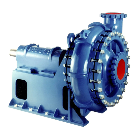
General description The Workhorse for the toughest services The Model 5500 severe duty slurry pumps are engineered and manufactured for dependable performance and long life. Tested under punishing conditions, these heavy duty pumps stay the course and keep working efficiently. -
Page 16: Nameplate Information
Rated pump head, in feet MAT'L. Material of which the pump is constructed IMP. DIA. Impeller diameter, in inches CONT./ITEM NO. Customer contract or item number MAX. DIA. Maximum impeller diameter, in inches Model 5500 Installation, Operation, and Maintenance Manual... - Page 17 Rated pump head, in m MAT'L. Material of which the pump is constructed IMP. DIA. Impeller diameter, in inches CONT./ITEM NO. Customer contract or item number MAX. DIA. Maximum impeller diameter, in inches Model 5500 Installation, Operation, and Maintenance Manual...
-
Page 18: Installation
• Foundation bolts should be 3.175 - 6.350mm | 0.125 - 0.250 in. smaller in diameter than the pump frame hole size. The hole size is shown on the certified dimension drawing. Model 5500 Installation, Operation, and Maintenance Manual... -
Page 19: Suction And Discharge Pipe
4. Proper belt tension is the primary reason for long belt life. Improper tension could cause belt fatigue and/or hot bearings. The general method for tensioning belts is given below, and should satisfy most drive requirements. Model 5500 Installation, Operation, and Maintenance Manual... -
Page 20: Pump-To-Drive Alignment
• Electrical connections must be made by certified electricians in compliance with all international, national, state, and local rules. • Refer to driver/coupling/gear manufacturer's installation and operation manuals (IOM) for specific instructions and recommendations. Model 5500 Installation, Operation, and Maintenance Manual... - Page 21 1. Mount two dial indicators on one of the coupling halves (X) so they contact the other coupling half (Y). 2. Check setting of indicators by rotating coupling half X to ensure indicators stay in contact with coupling half Y but do not bottom out. Adjust indicators accordingly. Model 5500 Installation, Operation, and Maintenance Manual...
- Page 22 • Add shims in order to raise the feet of the driver at the shaft end. • Remove shims in order to lower the feet of the driver at the other end. Model 5500 Installation, Operation, and Maintenance Manual...
- Page 23 Negative The pump coupling half (X) is lower than the driver coupling half (Y). Remove shims of a thickness equal to half of the indicator reading value under each driver foot. Model 5500 Installation, Operation, and Maintenance Manual...
- Page 24 The permitted value is 0.10 mm | 0.004 in. or less. Seal the shaft with a packed stuffing box Goulds Model 5500 pumps are properly packed at the factory. The packing gland is set finger- tight and may require adjustment during start-up. Refer to...
- Page 25 10. Periodic maintenance is absolutely required for all packed pumps. Normal shaft run-out should be under 0.127mm | .005in to avoid pounding of stuffing box packing. With excessive shaft run-out, shaft straightening or replacement is necessary. Model 5500 Installation, Operation, and Maintenance Manual...
-
Page 26: Commissioning, Startup, Operation, And Shutdown
When the pump is first started, there should be considerable leakage by the gland to cool the packing. 2. Gradually tighten the gland nuts one flat at a time while observing the leakage and the stuffing box temperature. Model 5500 Installation, Operation, and Maintenance Manual... -
Page 27: Shaft-Sealing Options
In most cases, the manufacturer seals the shaft before shipping the pump. If your pump does not have a sealed shaft, see the Shaft-seal maintenance section in the Maintenance chapter. This model uses these types of shaft seals: • Cartridge mechanical seal Model 5500 Installation, Operation, and Maintenance Manual... -
Page 28: Maintenance
150 SSU at the operating temperature to prevent accelerated bearing wear. Table 6: Acceptable oil Operating Temperature Gear Oil Below 71°C | 160°F SAE40 Below 82°C | 180°F SAE 50 or 90 Below 99°C | 210°F SAE140 Model 5500 Installation, Operation, and Maintenance Manual... -
Page 29: Prepare The Stuffing Box Connection
3. Install a valve in the gland water line to limit pressure to the optimum for the actual conditions of service. NOTICE: Excessive pressure will increase water consumption, gland water leakage and shaft sleeve wear. Model 5500 Installation, Operation, and Maintenance Manual... -
Page 30: Set The Impeller Adjustment
Suction cover liner must be supported before removing suction cover. Failure to do so could result in personal injury and property damage. 8. Unbolt and remove suction cover (182). See Remove the suction cover (page 30). 9. Remove gasket (351). Model 5500 Installation, Operation, and Maintenance Manual... - Page 31 A special tool is available from Goulds Pumps, Inc. to turn the shaft. The impeller must be supported before the impeller is completely unscrewed. A special tool to hold the impeller is also available from Goulds Pumps Inc.
-
Page 32: Remove The Suction Cover
20. Slide shaft sleeve (126) from shaft (122). Sleeve has a female threaded end to engage with a standard pipe thread. A sleeve puller tool is available from Goulds Pumps, Inc. A pipe nipple of the correct size can also be screwed in to the sleeve end to provide an easy way to attache and pull the sleeve from the shaft. -
Page 33: Guidelines For Parts Inspection And Replacement
3. Press oil seals (332, 332A, 333, 333A) into both end covers (109, 119). Fill the cavity between the seals with grease. Inspect O-Ring (496) on outboard end cover (109) and replace if necessary. 4. Position oil thrower (114) on shaft and secure between bearing fits. B5 Frame only. Model 5500 Installation, Operation, and Maintenance Manual... -
Page 34: Reassemble The Pump
A tool to help maintain alignment is available from Goulds Pumps, lnc. For the B5 frame, position hole in inboard bearing outer race so that it will engage properly with the inboard bearing locking screw (136A). - Page 35 Figure 17: Tighten bolts 20. Wrench tighten bolts repeatedly using the criss-cross pattern until the torque value listed in following table is reached. Table 10: 5500 Casing bolt torque values Lubricate threads before tightening Pump size Torque (ft lbs) suction side...
- Page 36 27. Check drive or coupling alignment as noted in Section II. 28. Follow procedures listed under “Pump Start-Up” for proper lubrication requirements. Be sure to add oil to the bearing housing prior to running the pump. Model 5500 Installation, Operation, and Maintenance Manual...
- Page 37 1. Determine if the center of the base- be obtained (angular or parallel). is probably bowed. plate should be raised or lowered. 2. Level screws equally at the center of the baseplate. 3. Realign the pump and driver. Model 5500 Installation, Operation, and Maintenance Manual...
- Page 38 Parts Listings and Cross-Sectionals Parts Listings and Cross-Sectionals Assembly drawings (exploded views) Table 13: Parts List Item Description Casing Impeller LANTERN RING Model 5500 Installation, Operation, and Maintenance Manual...
- Page 39 HEX CAP SCREWS (OUTBOARD END COVER) 370P HEX CAP SCREWS (INBOARD END COVER) 382A OUTBOARD BEARING LOCKWASHER DRIVE KEY BEARING HOUSING CLAMP SUCTION COVER CLAMP HEX SOCKET CAP SCREW O-RING (OUTBOARD END COVER) GASKET (EXPELLER - IMPELLER) Model 5500 Installation, Operation, and Maintenance Manual...
- Page 40 Visit our website for the latest version of this document and more information: http://www.gouldspumps.com Goulds Pumps Inc. 240 Fall Street Seneca Falls, NY 13148 Form IOM.5500-en.US-2018.08 © 2018 ITT Corporation The original instruction is in English. All non-English instructions are translations of the original...
Need help?
Do you have a question about the 5500 and is the answer not in the manual?
Questions and answers