
Subscribe to Our Youtube Channel
Related Manuals for Goulds Pumps 2GFK3812A


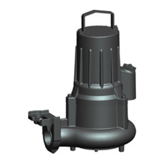
Summary of Contents for Goulds Pumps 2GFK3812A
- Page 1 Installation, Operation, and Maintenance Manual 887072_3.0 GFK-GFV Series Submersible Sewage Pumps...
- Page 3 Pump models included in the IOM Pump models included in the IOM 2GFK3812A 2GFV3812J 2GFK3813A 2GFV3813J 2GFK3814A 2GFV3814J 2GFK3815A 2GFV3815J 2GFK3212G 2GFV3212K 2GFK3213G 2GFV3213K 2GFK3214G 2GFV3214K 2GFK3215G 2GFV3215K 2GFK2412H 2GFK2413H 2GFK2414H 2GFK2415H GFK-GFV Series Installation, Operation, and Maintenance Manual...
-
Page 4: Table Of Contents
Table of Contents Table of Contents 1 Introduction and Safety................................2 1.1 Introduction....................................2 1.2 Safety terminology and symbols..............................2 1.3 User safety.....................................2 1.4 Ex-approved products................................2 1.5 Special hazards.................................... 3 1.6 Protecting the environment................................3 1.7 Spare parts....................................3 1.8 Warranty......................................3 2 Transportation and Storage...............................3 2.1 Examine the delivery................................... -
Page 5: Introduction And Safety
1 Introduction and Safety Electrical hazard Magnetic fields hazard 1 Introduction and Safety Electrical Hazard: CAUTION: 1.1 Introduction 1.3 User safety Purpose of the manual The purpose of this manual is to provide necessary information for All regulations, codes, and health and safety directives must be ob- working with the unit. -
Page 6: Special Hazards
2 Transportation and Storage • The width of flameproof joints is more than the values specified in Exceptional sites the tables of the IEC 60079–1 standard. CAUTION: Radiation Hazard • The gap of flameproof joints is less than the values specified in Ta- ble 1 of the IEC 60079–1 standard. -
Page 7: Lifting
3 Product Description Below –13°C (9°F), the viscosity increases such that the glycol mixture 2.2.1 Lifting will lose its flow properties. However, the glycol-water mixture will not Always inspect the lifting equipment and tackle before starting any solidify completely and thus cannot harm the product. work. -
Page 8: Monitoring Equipment
3 Product Description • The monitoring equipment must be of a design that makes auto- Parts matic restart impossible. • Information in the junction box shows if the pump is equipped with optional sensors Optional sensors LD LD is a miniature float switch for detection of liquid in the stator housing. -
Page 9: Installation
4 Installation Codes and parameters General requirements XXYYYY YYY YYY YYYY These requirements apply: • Use the pump dimensional drawing in order to ensure proper in- stallation. Before installing the pump, do the following: • Provide a suitable barrier around the work area, for example, a guard rail. -
Page 10: Install With Free-Standing Installation
4 Installation • Guide bars • Guide bar bracket for attaching the guide equipment to the access frame or to the upper part of the sump • Level regulators or other control equipment for start, stop, and alarm • Cable holder for holding the cable and regulating the height of the level regulators •... -
Page 11: Connect The Motor Cable To The Pump
4 Installation WARNING: Electrical Hazard WARNING: Electrical Hazard There is a risk of electrical shock or explosion if the electrical If the power cable is jerked loose, then the ground (earth) connections are not correctly carried out, or if there is fault or conductor must be the last conductor to come loose from its damage on the product. -
Page 12: Cable Charts
4 Installation 4.2.3 Cable charts Description L1 L2 L3 T1 T2 T3 T4 This topic contains general connection information. It also provides ca- ble charts that show connection alternatives for use with different ca- bles and power supply. T1 T2 1. - Page 13 4 Installation 3-phase connection V1 W1 W5 V2 W2 U6 W6 U5 V5 U1 V1 W1 W2 V2 U1 V1 W1 W2 U2 V2 U1 V1 W1 W2 U2 V2 U1 V1 W1 W2 U2 V2 U1 V1 W1 W2 U2 V2 Y-SER U1 V1 W1 W2 U2 V2 U1 V1 W1...
-
Page 14: Check The Impeller Rotation
5 Operation The correct direction of impeller rotation is clockwise when you look at the pump from above. SUBCAB 4GX/7G SUBCAB AWG H07RN-F* Control 4. If the impeller rotates in the wrong direction, then do one of these steps: WH T1 BK 4 –... -
Page 15: Maintenance
6 Maintenance 6 Maintenance 6.1 Change the coolant This image shows the plug that is used to change the coolant. Precautions Before starting work, make sure that the safety instructions in the chap- Introduction and Safety on page 2 have been read and understood. DANGER: Crush Hazard Moving parts can entangle or crush. -
Page 16: Service The Pump
6 Maintenance ™ • Statoil MedicWay 32 6.2.1 Inspection ™ • BP Enerpar M 004 ™ • Shell Ondina 927 Service item Action ™ • Shell Ondina X430 Cable 1. If the outer jacket is damaged, replace 1. Fill with coolant. the cable. -
Page 17: Replace The Impeller
6 Maintenance The proper lubrication is grease for bearings, for example Exxon Alarm source Action Mobil Unirex N3, Mobil Mobilith SHC 220 or equivalent. Overload protection Check that the impeller can rotate freely. NOTICE: Surplus grease can cause the impeller to become loose. Remove 6.3 Replace the impeller surplus grease from conical and/or cylindrical surfaces of shafts and/or sleeves. -
Page 18: Troubleshooting
7 Troubleshooting Figure 12: Vortex (L) 4. Fasten the impeller. Impeller Action type Non-clog Hand-tighten the impeller screw enough to prevent it from falling off. Do not fasten the impeller until the clearance has been adjusted in step on page 15. The clearance (A): 0.2–0.8 mm (0.008–0.032 in.) Vortex (H) Fasten the impeller by tightening the impeller screw. -
Page 19: The Pump Does Not Start
7 Troubleshooting 7.1 The pump does not start 7.2 The pump does not stop when a level sensor is used DANGER: Crush Hazard Moving parts can entangle or crush. Always disconnect and DANGER: Crush Hazard lock out power before servicing to prevent unexpected start- Moving parts can entangle or crush. -
Page 20: The Pump Runs But The Motor Protection Trips
8 Technical Reference 7.4 The pump runs but the motor protection 7.5 The pump delivers too little or no water trips DANGER: Crush Hazard Moving parts can entangle or crush. Always disconnect and DANGER: Crush Hazard lock out power before servicing to prevent unexpected start- Moving parts can entangle or crush. - Page 21 8 Technical Reference Feature Description Maximum starts per hour 15 evenly-spaced starts per hour Code compliance IEC 60034-1 Voltage variation without over- ±10%, if it does not run continuously heating at full load Voltage imbalance tolerance Stator insulation class F (155°C [311°F]) Motor encapsulation Motor encapsulation is in accordance with IP68.
- Page 24 The original instruction is in English. All non-English P.R. China instructions are translations of the original instruction. Tel: +86-24-25263000 Fax: © 2018 Xylem Inc Goulds is a registered trademark of Goulds Pumps, Inc. and is used under license. 887072_3.0_en-US_2018-05_IOM.1310_1.0_en-US_A_GFK-GFV Series...
Need help?
Do you have a question about the 2GFK3812A and is the answer not in the manual?
Questions and answers