Table of Contents
Advertisement
Available languages
Available languages
Quick Start Guide
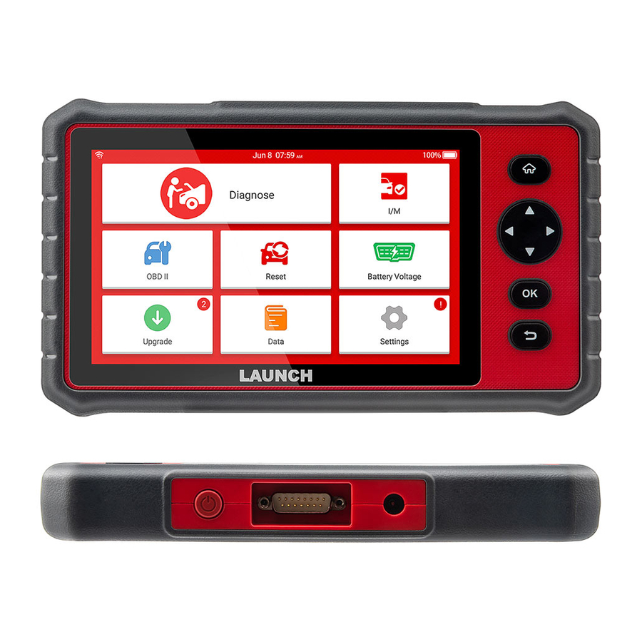
Display Tablet
DB-15 Diagnostic Connector
(To connect to vehicle's DLC (Data
Link Connector) via diagnostic cable.)
5 V Charging Port
(To connect to external DC
power for charging the tool.)
OK Button
Return Button
1
Charging & Turning On
There are two charging methods available:
Via Charging Cable: Plug one end of the included charging cable into
the 5 V charging port of the tool, and the other end to the external DC
power.
Via Diagnostic Cable: Insert one end of the diagnostic cable into the
DB-15 connector of the tool, and the other end to the vehicle's DLC.
Once the charging LED illuminates solid green, it indicates that the
battery is fully charged.
Press the [Power] button to power it on.
2
If it is the first time you have used this tool, you need to make some
7" Touch Screen
system settings and keep the diagnostic software synchronized with
the latest version.
Selection Buttons
Follow the steps below to proceed.
Power/Screen
Lock Button
Tap "Start" on Welcome screen
HOME Button
Getting Started
Select system language
Select time zone
WLAN setup
Configure email address
Sign user agreement
Job Menu appears
Tap "Update"
LAUNCH
*Note: If you choose "Ignore" in
this step, it will go into the date
setting page. If the tool has been
properly connected to the Internet,
the system will automatically
obtain the correct network date and
time.
*Note: After you configured it,
the system will automatically
send the diagnostic report to your
email box every time a complete
Auto-Detect process is
successfully finished.
*Note: To enjoy more capabilities
and better service, you are
strongly recommended to update
it on regular basis.
Advertisement
Table of Contents

Subscribe to Our Youtube Channel
Related Manuals for Launch DB-15


Summary of Contents for Launch DB-15
- Page 1 Job Menu appears Via Diagnostic Cable: Insert one end of the diagnostic cable into the DB-15 connector of the tool, and the other end to the vehicle's DLC. *Note: To enjoy more capabilities Once the charging LED illuminates solid green, it indicates that the and better service, you are Tap “Update”...
- Page 2 In case no DLC is found, please refer to Automobile Repair Manual. Decoding OK Decoding failed 3. Plug one end of the diagnostic cable into the DB-15 connector of Select vehicle make the tool, and tighten the captive screws. Connect the other end to Double check vehicle info.
-
Page 3: Guide De Démarrage Rapide
CC externe. Le menu de travail apparaît Via le câble de diagnostic: Insérez une extrémité du câble de diagnostic dans le connecteur DB-15 de l'outil et l'autre extrémité *Remarque: Pour bénéficier de dans le DLC du véhicule. - Page 4 échoué 3. Branchez une extrémité du câble de diagnostic sur le connecteur Vérifier les informations du Sélectionner la marque DB-15 de l'outil et serrez les vis imperdables. Connectez l'autre véhicule du véhicule extrémité au DLC du véhicule. Numériser tous les systèmes Sélectionner le système d'essai...
-
Page 5: Guía De Inicio Rápido
CC externa. A través de Cable de Diagnóstico: Inserte un extremo del cable de Aparece el Menú Trabajo diagnóstico en el conector DB-15 de la herramienta, y el otro extremo al DLC del vehículo. *Nota: Para disfrutar de más capacidades y un mejor servicio, Una vez que el LED de carga se ilumina en verde sólido, indica que la... - Page 6 Decodificación fallida Reparación de Automóviles. vehículo Comprobar la información 3. Enchufe un extremo del cable de diagnóstico en el conector DB-15 del vehículo de nuevo de la herramienta y apriete los tornillos cautivos. Conecte el otro Seleccione la marca del vehículo extremo al DLC del vehículo.
-
Page 7: Краткое Руководство
5V, и подключите другой конец кабеля к внешнему источнику питания постоянного тока. Через диагностический кабель: Вставьте диагностический Главное меню появляется кабель в гнездо разъема DB-15, подключите другой конец к разъему DLC автомобиля. *Внимание: Чтобы получить Если индикатор аккумулятора горит зеленым цветом, это... - Page 8 в порядке выполнить гнезда не найдено, см. руководство по ремонту. автомобиля расшифровку 3. Вставьте диагностический кабель в гнездо разъема DB-15, Дважды проверьте информацию затяните невыпадающий винт. Подключите другой конец об автомобиле. Выберите марку автомобиля диагностического кабеля к диагностическому разъему DLC.
- Page 9 Ladekabels in 5V-Ladeanschluss des Geräts und das andere Ende in die externe Gleichstromversorgung. Über das Diagnosekabel: Stecken Sie ein Ende des Diagnosekabels Das Auftragsmenü wird angezeigt in den DB-15-Stecker des Geräts und das andere Ende in DLC des *Hinweis: Um mehr Funktionen Fahrzeugs. und einen besseren Service zu Sobald die LED für Laden grün leuchtet, zeigt es an, dass die...
- Page 10 Überprüfen Sie die Autoreparatur. Wählen Sie Fahrzeugmarke aus Fahrzeuginformationen erneut. 3. Stecken Sie ein Ende des Diagnosekabels in den DB-15-Stecker des Geräts und ziehen die unverlierbaren Schrauben fest. Schließen Sie das andere Ende an DLC des Fahrzeugs an. Wählen Sie Testsystem aus...
-
Page 11: Guida Rapida
DC esterna. Tramite cavo diagnostico: inserire un'estremità del cavo diagnostico Viene visualizzato il menu Lavoro nel connettore DB-15 dell'utensile e l'altra estremità al DLC del veicolo. *Nota: Per godere di più Una volta che il LED di ricarica illumina di verde solido, indica che la funzionalità... - Page 12 Automobile Repair Manual. Produttore del veicolo selezionato Decodifica OK Decodifica non riuscita 3. Collegare un'estremità del cavo diagnostico nel connettore DB-15 dell'utensile e stringere le viti in cattività. Collegare l'altra Controllare le informazioni estremità al DLC del veicolo. Selezionare la marca del veicolo...
- Page 13 LAUNCH クイックスタートガイド 起動 ディスプレイタブレット DB-15 診断コネクター 当ツールを初めて利⽤する場合、システム設定と最新診断ソフトウェ 7" タッチスクリーン アバージョンへの同期が必要となります。 (診断ケーブル経由で⾞両DLCに接続 選択ボタン 次の⼿順により設定してください。 します(データリンクコネクター)) 歓迎画⾯で「起動」 5V充電ポート 電源/画⾯ロックボタン をタップしてください。 (外部DC電源に接続し、 ホームボタン 充電します) システム⾔語を選択してください *注 意:「 無 視 」 を 選 択 し る と 、 デ ー タ 設 定 ペ ー ジ に ⼊ り ま す 。...
- Page 14 診断フローチャート ⼿動診断フローチャート ンチ離れます。DLC位置を確 認してください。DLCがダッ *⾞両診断を始めて⾏う場合、 「診断」をタップしてください* シュボートの下に取り付けら ダッシュボー 「デモ」で診断プロセスに馴 れていない場合、位置を表⽰ トの中⼼付近 染むことが推奨されます。 ⾞両VINデコードを するラベルが提供されます。 開始してください ⾞両ブランドを選択してください DLCなしの場合、⾃動⾞修理マニュアルをご参照ください。 デコード失敗しました デコードOK 3. 診断ケーブルの⼀端を当ツールのDB-15コネクターに挿⼊し、スク ⾞両メーカーを選択してください リューを締め、固定してください。ほかの⼀端を外部DC電源に接 ⾞両情報を再確認 してください 続してください。 テストシステムを ⾞両情報を全部 選択してください 診断ケーブル スキャンしてください 診断機能を選択してください* 診断報告を出⼒してください VINを⼊⼒し、「OK」をタップし、システムは⾃動的に⾞種を識別 します。⾞両VINが成功にデコードされると、診断報告が出⼒され ⾞両 ディスプレイタブレット るまで⾃動診断が⾏われます。 *注意: 標準OBD-II診断ソケット搭載の12V乗⽤⾞のみに利⽤可能...
-
Page 15: Guia De Início Rápido
à alimentação DC externa. Menu de Trabalho aparece Via cabo de diagnóstico: insira uma extremidade do cabo de diagnóstico no conector DB-15 da ferramenta e a outra extremidade *Nota: Para aproveitar mais no DLC do veículo. - Page 16 Preparação Inicie o diagnóstico Detecção automática e diagnóstico manual são suportados. Se a 1. Desligue a ignição. detecção automática falhar, você poderá inserir o VIN manualmente 2. Localize o DLC do veículo: ou sair da sessão da detecção automática para alternar para o modo Ele fornece 16 pinos Localização do DLC de diagnóstico manual.
- Page 17 7" Touch Screen 正面 此处为语言标签, 制作要求: 在裁剪时请注意 原始文件大小: 210mm x 148mm, 按1:1输出 折叠方式: 骑马钉 印刷要求: 黑白印刷, 80g内页纸...
Need help?
Do you have a question about the DB-15 and is the answer not in the manual?
Questions and answers