Table of Contents
Advertisement
Quick Links
LAUNCH
Copyright Information
Copyright © 2023 by LAUNCH TECH CO., LTD. (also called LAUNCH for
short). All rights reserved. No part of this publication may be reproduced, stored
in a retrieval system, or transmitted in any form or by any means, electronic,
mechanical, photocopying and recording or otherwise, without the prior written
permission.
Statement: LAUNCH owns the complete intellectual property rights for the
software used by this product. For any reverse engineering or cracking actions
against the software, LAUNCH will block the use of this product and reserve the
right to pursue their legal liabilities.
Disclaimer of Warranties and Limitation of Liabilities
All information, illustrations, and specifications in this manual are based on the
latest information available at the time of publication.
The right is reserved to make changes at any time without notice. We shall not
be liable for any direct, special, incidental, indirect damages or any economic
consequential damages (including the loss of profits) due to the use of the
document.
i
Advertisement
Table of Contents

Subscribe to Our Youtube Channel
Related Manuals for Launch Creader Elite 2.0 BBA


Summary of Contents for Launch Creader Elite 2.0 BBA
- Page 1 Statement: LAUNCH owns the complete intellectual property rights for the software used by this product. For any reverse engineering or cracking actions against the software, LAUNCH will block the use of this product and reserve the right to pursue their legal liabilities.
- Page 2 LAUNCH WARNING Study, understand and follow all instructions provided with this product. Read these instructions carefully before installing, operating, servicing or repairing this tool. Keep these instructions in a safe, accessible place. Caution: To help prevent personal injury, • Never use this tool for any application other than for which it was designed.
- Page 3 LAUNCH Compliance Information FCCID: XUJOCEX403 Any Changes or modifications not expressly approved by the party responsible for compliance could void the user’s authority to operate the equipment. This device complies with part 15 of the FCC Rules. Operation is subject...
-
Page 4: Table Of Contents
LAUNCH Table of Contents 1. Introduction ....................1 1.1 Vehicle Coverage ..................1 1.2 On-Board Diagnostics (OBD) II ..............2 1.3 OBD II Definitions ..................2 1.4 Diagnostic Trouble Codes (DTCs) ..............4 1.5 Location of the Data Link Connector (DLC)........... 5 2. - Page 5 LAUNCH 7.6 Time Zone....................24 7.7 Language..................... 24 7.8 Workshop information .................. 24 7.9 Recovery ..................... 24 7.10 Clean Up....................25 7.11 Screen Capture ..................25 7.12 About ......................25 7.13 Data ......................25 7.13.1 Diagnostic Record .................. 25 7.13.2 Diagnostic Report ................... 25 7.13.3 DTC Library ....................
-
Page 6: Introduction
LAUNCH 1. Introduction 1.1 Vehicle Coverage This diagnostic tool is specially designed to work with all OBD II compliant vehicles, including Controller Area Network (CAN). It is required by EPA that all 1996 and newer vehicles (cars and light trucks) sold in the United States must be OBD II compliant and this includes all American, Asian and European vehicles. -
Page 7: On-Board Diagnostics (Obd) Ii
LAUNCH 1.2 On-Board Diagnostics (OBD) II The OBD II system is designed to monitor emission control systems and key engine components by performing either continuous or periodic tests of specific components and vehicle conditions, which will offer three pieces of such valuable information: •... - Page 8 LAUNCH Monitors - Monitors are “diagnostic routines” programmed into the PCM. The PCM utilizes these programs to run diagnostic tests, and to monitor operation of the vehicle’s emissions-related components or systems to ensure they are operating correctly and within the vehicle’s manufacturer specifications.
-
Page 9: Diagnostic Trouble Codes (Dtcs)
LAUNCH refers to much more gradual adjustments to the fuel calibration schedule than short-term trim adjustments. These long-term adjustments compensate for vehicle differences and gradual changes that occur over time. 1.4 Diagnostic Trouble Codes (DTCs) OBD II Diagnostic Trouble Codes are codes that are stored by the on-board computer diagnostic system in response to a problem found in the vehicle. -
Page 10: Location Of The Data Link Connector (Dlc)
LAUNCH 1.5 Location of the Data Link Connector (DLC) The DLC (Data Link Connector or Diagnostic Link Connector) is typically a 16- pin connector where diagnostic code readers interface with the vehicle’s on- board computer. It is usually located 12 inches from the center of the instrument panel, under or around the driver’s side for most vehicles. -
Page 11: Product Descriptions
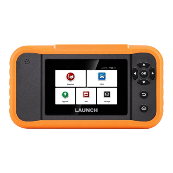
LAUNCH 2. Product Descriptions 2.1 Components & Controls Name Descriptions Charging port Charge the tool via data cable (not included). DB-15 diagnostic Connect the diagnostic cable. connector Power button Turn on/off the tool. Touch screen Indicate the test results. OK button Confirm a selection (or action) from a menu list. -
Page 12: Technical Specifications
LAUNCH 2.2 Technical Specifications • Screen: 4” touch screen with a resolution of 480*800 • CPU: 4-core 1.5GHz processor • RAM: 2GB • ROM: 32GB • WiFi: 802.11b/g/n 2.4GHz • OBD II input voltage range: 9~18V • Power up via: •... -
Page 13: Initial Use
LAUNCH 3. Initial Use 3.1 Powering Up The Tool There are two methods available for powering up the tool: Via Data Cable: Plug one end of data cable (not included) into the charging port of the tool, and the other end to the PC. - Page 14 LAUNCH This option presents a quick way to check for DTCs, isolate the cause of the illuminated Malfunction Indicator Lamp (MIL), OBD II check monitor status prior to emissions certification testing, verify repairs, and perform a number of other services that are emission-related.
-
Page 15: Diagnose
LAUNCH 4. Diagnose 4.1 Connection 1). Turn the ignition off. 2). Locate the vehicle’s 16-pin Data Link Connector (DLC). Refer to Chapter 1.5. 3). Plug one end of the diagnostic cable into the vehicle’s DLC(Data Link Connector) port, and the other end to the DB-15 diagnostic connector of the tool, and then tighten the captive screws. -
Page 16: System Diagnosing
LAUNCH Caution: Don’t connect or disconnect any test equipment with ignition on or engine running. 4.2 System Diagnosing This function is specially designed to diagnose electronic control systems of single vehicle model. *Notes: 1. The diagnostic software of the vehicle includes all kinds of reset software, user can perform it (select Special function from the diagnostic function list) directly in this module. -
Page 17: Manual Diagnosis
LAUNCH Input the VIN, and tap “OK”, the system will decode the VIN data automatically, and continue the Smart Diagnosis procedure if success. Otherwise the system will enter the Manual Diagnosis mode. *Notes: • The most recognizable location for this number is in the top left corner on the vehicle’s dashboard. - Page 18 LAUNCH Select “Diagnose” Select Vehicle Manufacturer Select Vehicle Model Select Scan Mode Automatic System Detection Manual System Detection (System Scan) (System Selection) Select Test Function Special Read Data Clear Fault Read Fault Read Version Functions* Stream Code Code Information Take DEMO V15.34 as an example to demonstrate how to diagnose a vehicle.
- Page 19 LAUNCH 3). Turn the ignition key to ON: Set the ignition switch to on. 4). Read vehicle information: After reading the vehicle information, double check if the vehicle information is correct or not. If yes, tap “Yes” to continue. 5). Select test item: Select the desired test item to proceed.
- Page 20 LAUNCH In above figure, the tested system with fault code is tagged with a red cross and the system with OK displays with a green tick. On-Screen Buttons: Report: Tap to save the diagnostic result as a report. Clear Code: Tap to clear the existing diagnostic trouble codes.
- Page 21 LAUNCH display the diagnostic result. *Note: Retrieving and using DTCs for troubleshooting vehicle operation is only one part of an overall diagnostic strategy. Never replace a part based only on the DTC definition. Each DTC has a set of testing procedures, instructions and flow charts that must be followed to confirm the location of the problem.
- Page 22 LAUNCH On-Screen Buttons: Select All: Tap it to select all items of the current page. To select certain data stream item, just check the box before the item name. Unselect: Tap it to deselect all data stream items. OK: Tap it to confirm and jump to the next step.
- Page 23 LAUNCH different items are marked in different colors. On-Screen Buttons: : Tap it to view the waveform graph of the current data stream item. Combine: Tap it, a pull-down list of the data stream items appears on the screen. Select the necessary items (Max. 4 items can be selected at the same time) and the screen will display the waveforms corresponding to these items immediately.
-
Page 24: Obd Ii Diagnosis
LAUNCH 4.3 OBD II Diagnosis This function presents a quick way to check for DTCs, isolate the cause of the illuminated Malfunction Indicator Lamp (MIL), check monitor status prior to emissions certification testing, verify repairs, and perform a number of other services that are emission-related. -
Page 25: History
LAUNCH 7. On-board monitor test This function retrieves test results for emission-related powertrain components and systems that are not continuously monitored. The test’s availability is determined by the vehicle manufacturer. 8. EVAP System Test This function lets you initiate a leak test for the vehicle’s EVAP system. Refer to the vehicle’s service repair manual to determine the procedures necessary to... -
Page 26: Upgrade
LAUNCH 5. Upgrade This function allows you to update the diagnostic app and software. All software is updated periodically. It is recommended to update and install the latest software version for the best service, functions and experience. 1). Use and update of the diagnostic software pre-installed on the tool is free of charge forever. - Page 27 LAUNCH then follow the on-screen instructions to finish the renewal. Now the latest diagnostic software is ready for use.
-
Page 28: Mall
LAUNCH 6. Mall This function allows you to subscribe other vehicle diagnostic software and reset software that are not pre-installed on the tool. All diagnostic software in the mall covers full systems and full functions (excluding online programming and coding etc). Different vehicle software is tagged with different price. -
Page 29: Settings
LAUNCH 7. Settings 7.1 Units of measurement This option can set the measurement unit. Metric System and English System are available. 7.2 Automatic detection on connect This option enables you to determine whether to start an automatic VIN detection once the tool is properly connected to the vehicle’s DLC. -
Page 30: Clean Up
LAUNCH Warning: Resetting may cause data loss. Before doing so, please be careful to perform this operation. 7.10 Clean Up This option allows user to clear some cache files and free up the storage space. 7.11 Screen Capture This option can set the Screen Capture icon to be shown or not on the screen. -
Page 31: Feedback
LAUNCH 7.13.5 Feedback This function allows you to send the feedback of your diagnostic problems to us for further analysis and troubleshooting. 7.13.6 Image This option allows you to view and manage all screenshots. All screenshots created in the vehicle diagnostic work will be saved in this module. -
Page 32: Faq
LAUNCH 8. FAQ Here we list some frequently asked questions and answers related to this tool. 1. System halts when reading data stream. What is the reason? It may be caused by a slackened connector. Please turn this tool off, firmly connect the connector, and switch it on again. -
Page 33: Warranty
The exclusive remedy for any automotive meter found to be defective is repair or replacement, and LAUNCH shall not be liable for any consequential or incidental damages.
Need help?
Do you have a question about the Creader Elite 2.0 BBA and is the answer not in the manual?
Questions and answers