
Related Manuals for Dormakaba 9000DE Series


Summary of Contents for Dormakaba 9000DE Series
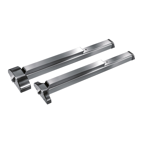
- Page 1 9000DE Series Delayed Egress Exit Device Installation instructions 95011817 - 01-2020 | EN |...
-
Page 2: Table Of Contents
9000 Delayed Egress Exit Device Installation Table of Contents Instructions Table of Contents Specifications Assembly Cylinder specifications DIP switch setting Basic wire connection Key switch operation for device Cover, end cap and label Pair of doors: 9100 DE Delayed Egress Exit... -
Page 3: Specifications Assembly
Assembly Note: R efer to individual series i nstallati o n instructi o ns for templati n g and installati o n of device; @ www.dormakaba.com These are additional instructions for installati o n and operati o n of the "Delayed Egress " unit. -
Page 4: Cylinder Specifications
9000 Delayed Egress Exit Device Installation Cylinder specifications Instructions DIP switch settings Cylinder specifications To Change Cylinder: Carefully remove filler from rail. Unscrew cylinder nut, remove actuator and replace cylinder. Spacer required for cylinders Standard 1 1/8" mortise cylinder, randomly over 1 1/8". -
Page 5: Basic Wire Connection
9000 Delayed Egress Exit Device Installation Basic wire connection Instructions Basic wire connection dormakaba MODEL ES100 Specific project or custom wiring diagrams available on re- 24 VOLT DC POWER SUPPLY quest, consult the dormakaba techinical service department. (AD100 220V Version Optional) -
Page 6: Key Switch Operation For Device
9000 Delayed Egress Exit Device Installation Key switch operation for device Instructions Key switch operation for device Delayed Egress Mode: Unit is armed and touch bar will not activate the latchbolt. (LED is solid green, audible alarm is off) . Initiated after power up, (DIP switch #2 in OFF position) authorized egress mode or re-arm mode. -
Page 7: Cover, End Cap And Label
9000 Delayed Egress Exit Device Installation Cover Instructions End Cap Label Cover, end cap and label After all wire connections are made and device checked for operation, install the chassis cover, end cap and label as shown below. NOTE: Compliance with the California Building Code (CBC) requires different label then supplied. -
Page 8: Pair Of Doors: 9100 De Delayed Egress Exit
9000 Delayed Egress Exit Device Installation Pair of door template Instructions Pair of doors: 9100 DE Delayed Egress Exit Devices x YR09LFSC Electric Trim (Fair Secure) x ES100 Power Supply x ES105 Power Transfer x 3914W Sounder x MC-4 DPS x Card Readers... -
Page 9: Single Door: 9300 De Delayed Egress Exit Device X Yr09Lfsc Electric Trim (Fail Secure) X Es100 Power Supply
9000 Delayed Egress Exit Device Installation Single door template Instructions Single Door: 9300 DE Delayed Egress Exit Device x YR09LFSC Electric Trim (Fail Secure) x ES100 Power Supply x ES105 Power Transfer x 3914W Sounder x MC-4 DPS x Card Readers... - Page 10 DORMA USA, Inc. T: 800-523-8483 www.dormakaba.us...
Need help?
Do you have a question about the 9000DE Series and is the answer not in the manual?
Questions and answers