
Related Manuals for Microchip Technology BM63


Summary of Contents for Microchip Technology BM63
- Page 1 BM63 Evaluation Board (EVB) User’s Guide Advance Information 2016 Microchip Technology Inc. DS70005274A Arrow.com. Downloaded from...
- Page 2 WiperLock, Wireless DNA, and ZENA are trademarks of Microchip Technology Incorporated in the U.S.A. and other countries. SQTP is a service mark of Microchip Technology Incorporated in the U.S.A. Microchip received ISO/TS-16949:2009 certification for its worldwide Silicon Storage Technology is a registered trademark of headquarters, design and wafer fabrication facilities in Chandler and Tempe, Arizona;...
- Page 3 BM63 EVB USER’S GUIDE Object of Declaration BM63 Evaluation Board Advance Information 2016 Microchip Technology Inc. DS70005274A - Page 3 Arrow.com. Arrow.com. Arrow.com. Downloaded from Downloaded from Downloaded from...
- Page 4 BM63 EVB User’s Guide NOTES: Advance Information 2016 Microchip Technology Inc. DS70005274A - Page 4 Arrow.com. Arrow.com. Arrow.com. Arrow.com. Downloaded from Downloaded from Downloaded from Downloaded from...
-
Page 5: Table Of Contents
Chapter 2. Hardware 2.1 Hardware Features ..................17 Chapter 3. Getting Started 3.1 Requirements ....................23 3.2 Getting Started with BM63 EVB ..............24 3.3 Application Demonstration ................25 3.4 Configuring BM63 Module ................27 3.5 Updating EEPROM Parameters ..............48 3.6 Updating Flash Code .................. - Page 6 BM63 EVB User’s Guide NOTES: Advance Information 2016 Microchip Technology Inc. DS70005274A - Page 6 Arrow.com. Arrow.com. Arrow.com. Arrow.com. Arrow.com. Arrow.com. Downloaded from Downloaded from Downloaded from Downloaded from Downloaded from Downloaded from...
- Page 7 Customer Support • Document Revision History DOCUMENT LAYOUT This document describes how to use the BM63 EVB, as a development tool to emulate and debug firmware on a target board. This user’s guide is composed of the following chapters: •...
- Page 8 BM63 EVB User’s Guide CONVENTIONS USED IN THIS GUIDE This manual uses the following documentation conventions: DOCUMENTATION CONVENTIONS Description Represents Examples Italic characters Referenced books MPLAB IDE User’s Guide Emphasized text ...is the only compiler... Initial caps A window the Output window...
- Page 9 Preface RECOMMENDED READING This user’s guide describes how to use the BM63 EVB. The following Microchip document is available and recommended as supplemental reference resources. BM63 Data Sheet (DS60001431) Refer to this document for a detailed information on the BM63 module. Reference information found in this data sheet includes: •...
- Page 10 BM63 EVB User’s Guide DEVELOPMENT SYSTEMS CUSTOMER CHANGE NOTIFICATION SERVICE Microchip’s customer notification service helps keep customers current on Microchip products. Subscribers will receive e-mail notification whenever there are changes, updates, revisions or errata related to a specified product family or development tool of interest.
- Page 11 Preface DOCUMENT REVISION HISTORY Revision A (July 2016) This is the initial released version of this document. Advance Information 2016 Microchip Technology Inc. DS70005274A - Page 11 Arrow.com. Arrow.com. Arrow.com. Arrow.com. Arrow.com. Arrow.com. Arrow.com. Arrow.com. Arrow.com. Arrow.com. Arrow.com. Downloaded from...
- Page 12 BM63 EVB User’s Guide NOTES: Advance Information 2016 Microchip Technology Inc. DS70005274A - Page 12 Arrow.com. Arrow.com. Arrow.com. Arrow.com. Arrow.com. Arrow.com. Arrow.com. Arrow.com. Arrow.com. Arrow.com. Arrow.com. Arrow.com. Downloaded from Downloaded from Downloaded from Downloaded from Downloaded from Downloaded from...
-
Page 13: Chapter 1. Introduction
Thank you for purchasing a Microchip Technology BM63 Evaluation Board (EVB). This document provides a detailed information about the BM63 EVB. The BM63 EVB enables the user to evaluate and demonstrate the functionality of the BM63 module. The BM63 EVB includes status LEDs and an integrated configuration and programming interface for plug-and-play capability, which enable rapid prototyping and faster time to market. - Page 14 FIGURE 1-1: Note: If you are missing any part of the BM63 EVB kit, contact a Microchip sales office for assistance. A list of Microchip offices for sales and service is pro- vided on the back page of this document.
-
Page 15: Bm63 Evb Features
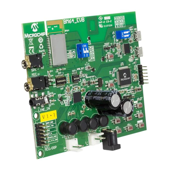
Introduction BM63 EVB FEATURES The following are key features of the BM63 EVB: • The BM63 EVB includes a BM63 module, qualified for Bluetooth 4.2 specifications • On-board MCU (PIC18F85J10) and DSP (YDA174) for easy operation and feature demonstration • On-board keypad matrix that is controlled by MCU, which makes it easy for play- back control •... - Page 16 BM63 EVB User’s Guide BM63 EVB (TOP VIEW) FIGURE 1-2: Advance Information 2016 Microchip Technology Inc. DS70005274A - Page 16 Arrow.com. Arrow.com. Arrow.com. Arrow.com. Arrow.com. Arrow.com. Arrow.com. Arrow.com. Arrow.com. Arrow.com. Arrow.com. Arrow.com. Arrow.com. Arrow.com. Arrow.com. Arrow.com. Downloaded from Downloaded from...
-
Page 17: Chapter 2. Hardware
The 15V DC power adapter for supplying power to the BM63 EVB. 2.1.2 USB connectivity The BM63 EVB has the following two USB ports that can be connected to the host PC using a micro-USB cable: • Debug or program port (P3), where the USB signals are converted to/from the UART by the MCP2200 •... - Page 18 BM63 EVB User’s Guide 2.1.3 Switches and Push buttons The functions of the switches and push buttons on the BM63 EVB are: • SW1 – Reset button for MCU • SW9 – Mode switch • SW10 – Reset button for BM63 module •...
- Page 19 • LED1 – Indicates the Bluetooth connection status (UI configuration dependent) • LED2 – Indicates the Bluetooth connection status (UI configuration dependent) • LED3 – Charging indication LED (default setting is disabled) Advance Information 2016 Microchip Technology Inc. DS70005274A - Page 19 Arrow.com. Arrow.com.
- Page 20 BM63 EVB User’s Guide 2.1.5 Headers The following three headers (J5, J6, JP23) are available on the BM63 EVB. The ICSP header J5 provides the programming/debugging interface for the BM63 EVB on-board MCU (PIC18F85J10). Figure 2-2 illustrates the ICSP header J5 and...
- Page 21 Hardware The external MCU/DSP header J6 provides the interface to connect an external MCU/DSP to the BM63 EVB. Figure 2-3 illustrates the external MCU/DSP header J6 Table 2-4 provides the pin details and description. FIGURE 2-3: EXTERNAL MCU/DSP HEADER J6...
- Page 22 BM63 EVB User’s Guide The MIC header JP23 is used for connecting a microphone to the BM63 EVB. Figure 2-4 illustrates the MIC header JP23 and Table 2-5 provides the pin details and description. FIGURE 2-4: MIC HEADER JP23 TABLE 2-5:...
-
Page 23: Chapter 3. Getting Started
BM63 EVB USER’S GUIDE Chapter 3. Getting Started This chapter describes how to establish a Bluetooth connection between the BM63 EVB and a host device. It also demonstrates the process of updating the parameters using various tools. This chapter includes the following topics: 3.1 “Requirements”... -
Page 24: Getting Started With Bm63 Evb
BM63 EVB User’s Guide GETTING STARTED WITH BM63 EVB To establish a Bluetooth connection between the BM63 EVB and a host device, per- form the following actions: 1. Set switch SW9 to Flash Application mode, see Figure 3-1. SW9 IN FLASH APPLICATION MODE FIGURE 3-1: 2. -
Page 25: Application Demonstration
7. Once the BM63 EVB is connected, LED1 (blue) starts blinking fast. This indicates that the BM63 EVB is in pairing mode. 8. When the BM63 EVB is paired with the host device, LED1 (blue) blinks twice at regular intervals. With the default settings, the BM63 module enables Advanced Audio Distribution Profile (A2DP) for audio playback and Audio Video Remote Control Profile (AVRCP) for player control. - Page 26 MIC input (P6) on the BM63 EVB. 3. Initiate a call from another phone to the smartphone, that is paired with the BM63 EVB. The A2DP stream pauses and the ringtone is played on the speaker. LED1 (blue) blinks three times at regular intervals.
-
Page 27: Configuring Bm63 Module
UI Tool Configuration The User Interface (UI) tool is a configuration tool which enables the user to change the BM63 module parameters. To configure the UI parameters, perform the following actions: 1. Open the UI configuration tool and click OK to configure the UI parameters, see Figure 3-5. - Page 28 BM63 EVB User’s Guide FIGURE 3-7: LOADING DEFAULT UI PARAMETERS 4. After loading the UI parameters, select “BM63” from the IC Package drop-down list and then click Edit, see Figure 3-8. FIGURE 3-8: EDIT UI PARAMETERS Advance Information 2016 Microchip Technology Inc.
- Page 29 Click Next. FIGURE 3-9: MAIN FEATURE SETTINGS Note: The audio output will be routed to the speaker if I S is not selected. Advance Information 2016 Microchip Technology Inc. DS70005274A - Page 29 Arrow.com. Arrow.com. Arrow.com. Arrow.com. Arrow.com.
- Page 30 BM63 EVB User’s Guide 6. The System and Functional Settings dialog with various options (tabs) is dis- played to configure the parameters. In the Sys. Setup2 tab, from Indication 1 Setting section, enable External Amplifier Indication, as illustrated in Figure 3- 10.
- Page 31 “Power On” Command, see Figure 3-11. The module will power-on by UART command and not by the MFB key. FIGURE 3-11: UART COMMAND SETTING Advance Information 2016 Microchip Technology Inc. DS70005274A - Page 31 Arrow.com. Arrow.com. Arrow.com. Arrow.com. Arrow.com.
- Page 32 BM63 EVB User’s Guide 8. After setting up the parameters, click Finish. A notification is displayed to check the EEPROM size on the system. Click OK, see Figure 3-12. FIGURE 3-12: EEPROM NOTIFICATION Advance Information 2016 Microchip Technology Inc.
- Page 33 10. From the Save As window, select the file location, and then click Save, see Figure 3-14. FIGURE 3-14: SAVE AS WINDOW 11. After saving the UI parameters, click Exit. Advance Information 2016 Microchip Technology Inc. DS70005274A - Page 33 Arrow.com. Arrow.com. Arrow.com. Arrow.com. Arrow.com.
- Page 34 Open the DSP tool and a dialog displays with various options (tabs) to configure the parameters, see Figure 3-15. Note: Download and install the DSP tool, which is available on the Microchip web site: www.microchip.com/BM63. For this demonstration DSPTool_IS206x_012_DualModeSPK1.1_v1.03 is used. FIGURE 3-15: DSP TOOL SETTINGS Advance Information 2016 Microchip Technology Inc.
- Page 35 Getting Started 2. In the Voice Function tab, set the parameters as illustrated in Figure 3-16. FIGURE 3-16: DSP VOICE FUNCTION SETTING Advance Information 2016 Microchip Technology Inc. DS70005274A - Page 35 Arrow.com. Arrow.com. Arrow.com. Arrow.com. Arrow.com. Arrow.com. Arrow.com.
- Page 36 BM63 EVB User’s Guide 3. In the Audio Function tab, set the parameters as illustrated in Figure 3-17. FIGURE 3-17: DSP AUDIO FUNCTION SETTING Advance Information 2016 Microchip Technology Inc. DS70005274A - Page 36 Arrow.com. Arrow.com. Arrow.com. Arrow.com. Arrow.com.
- Page 37 Getting Started 4. Click Save to save these DSP parameters as .txt file, see Figure 3-18. FIGURE 3-18: SAVING DSP PARAMETERS Advance Information 2016 Microchip Technology Inc. DS70005274A - Page 37 Arrow.com. Arrow.com. Arrow.com. Arrow.com. Arrow.com. Arrow.com. Arrow.com. Arrow.com.
- Page 38 BM63 EVB User’s Guide 5. After saving the DSP parameters, from the notification pop up, click OK, see Figure 3-19. Click Exit to exit the DSP tool settings. FIGURE 3-19: SAVE NOTIFICATION Advance Information 2016 Microchip Technology Inc. DS70005274A - Page 38 Arrow.com.
- Page 39 1. Open the MPET tool and then click Next to continue with the configuration settings, see Figure 3-20. Note: Download and install the MPET tool, which is available on the Microchip web site: www.microchip.com/BM63. For this demonstration MP_V2.1.29.4797 is used. FIGURE 3-20: MPET TOOL SETTING Advance Information 2016 Microchip Technology Inc.
- Page 40 BM63 EVB User’s Guide 2. Select UI Patch Only to merge the UI and the DSP parameters and then click Next, as illustrated in Figure 3-21. Note: For the UI parameter settings, refer to 3.4.1 “UI Tool Configuration”, for the DSP parameter settings, refer to 3.4.2 “DSP Tool...
- Page 41 3. Click Browse to load the default .bin file (provided with the MPET tool). From the Open window, select the file and then click Open, see Figure 3-22. .bin FIGURE 3-22: LOADING DEFAULT BIN FILE Advance Information 2016 Microchip Technology Inc. DS70005274A - Page 41 Arrow.com. Arrow.com. Arrow.com. Arrow.com. Arrow.com. Arrow.com. Arrow.com.
- Page 42 BM63 EVB User’s Guide 4. The bin file description is displayed, click Next, see Figure 3-23. FIGURE 3-23: DEFAULT BIN FILE SETTING Advance Information 2016 Microchip Technology Inc. DS70005274A - Page 42 Arrow.com. Arrow.com. Arrow.com. Arrow.com. Arrow.com. Arrow.com. Arrow.com.
- Page 43 5. Click the “+” button to load the UI and the DSP parameters (.txt file) into the MPET tool to merge with the EEPROM table and then click Next, as illustrated Figure 3-24. FIGURE 3-24: CUSTOMIZED SETTINGS TO MERGE Advance Information 2016 Microchip Technology Inc. DS70005274A - Page 43 Arrow.com. Arrow.com. Arrow.com. Arrow.com. Arrow.com.
- Page 44 BM63 EVB User’s Guide 6. Select an output file path to create the merged EEPROM table (.ipf file), and then click Next, see Figure 3-25. FIGURE 3-25: SELECTING OUTPUT FILE NAME AND PATH Advance Information 2016 Microchip Technology Inc.
- Page 45 Getting Started 7. Click Generate to generate the EEPROM table (.ipf file), see Figure 3-26. FIGURE 3-26: GENERATE EEPROM TABLE Advance Information 2016 Microchip Technology Inc. DS70005274A - Page 45 Arrow.com. Arrow.com. Arrow.com. Arrow.com. Arrow.com. Arrow.com. Arrow.com. Arrow.com. Arrow.com.
- Page 46 BM63 EVB User’s Guide 8. The calibration parameters included in the UI patch file can be selected or ignored and then click Next, see Figure 3-27. Note: If the items are selected, the calibration parameters of the.ipf file will over write the parameters in the device.
- Page 47 9. After generating the merged EEPROM table ( file), click Finish to exit the .ipf wizard, see Figure 3-28. FIGURE 3-28: MERGED EEPROM TABLE Advance Information 2016 Microchip Technology Inc. DS70005274A - Page 47 Arrow.com. Arrow.com. Arrow.com. Arrow.com. Arrow.com. Arrow.com. Arrow.com.
-
Page 48: Updating Eeprom Parameters
Figure 3-29. FIGURE 3-29: SWITCH SW9 IN TEST MODE 2. Connect the BM63 UART Connector (P3) port to a host PC using the micro-USB cable, see Figure 3-30. The default LED behavior in Test mode is: LED1 (blue) and LED2 (red) will be ON. - Page 49 Getting Started 3. Open the EEPROM tool and a window displays, see Figure 3-31. FIGURE 3-31: EEPROM TOOL Advance Information 2016 Microchip Technology Inc. DS70005274A - Page 49 Arrow.com. Arrow.com. Arrow.com. Arrow.com. Arrow.com. Arrow.com. Arrow.com. Arrow.com. Arrow.com. Arrow.com. Arrow.com.
- Page 50 BM63 EVB User’s Guide 4. Specify the COM Port and click IC/Module Identify, see Figure 3-32. FIGURE 3-32: EEPROM TOOL SETTINGS Advance Information 2016 Microchip Technology Inc. DS70005274A - Page 50 Arrow.com. Arrow.com. Arrow.com. Arrow.com. Arrow.com. Arrow.com. Arrow.com. Arrow.com.
- Page 51 Getting Started 5. Click Browse and select the generated patch file (.ipf) to write to the EEPROM parameter table on the BM63 EVB, see Figure 3-33. Note: The patch file ( ) is generated using the MPET tool. For information on .ipf...
- Page 52 BM63 EVB User’s Guide 6. Click Write to program the EEPROM parameters on the BM63 EVB. After pro- gramming the EEPROM parameters, a message is displayed. Click OK as illus- trated in Figure 3-34. FIGURE 3-34: WRITE EEPROM 7. Click Exit and remove the micro-USB cable. Then set switch SW9 to Flash Appli-...
-
Page 53: Updating Flash Code
Figure 3-36. FIGURE 3-36: SWITCH SW9 IN WRITE FLASH MODE 2. Connect the BM63 UART connector (P3) port to a host PC using a micro-USB cable, as illustrated in Figure 3-37. The default LED behavior in Write Flash mode is: LED1 (blue) and LED2 (red) will blink. - Page 54 Figure 3-39. FIGURE 3-39: LOADING FLASH CODE FILES 5. Click Update to write the Flash code on the BM63 module, Figure 3-40. Note: Alternately, the user can click Burst Update to write the Flash code which is faster than Update.
- Page 55 6. After the Flash code update, click Disconnect and then remove the micro-USB cable. Set SW9 to Flash Application mode (see Figure 3-35) and then reboot. Advance Information 2016 Microchip Technology Inc. DS70005274A - Page 55 Arrow.com. Arrow.com. Arrow.com.
-
Page 56: Updating Mcu Parameters
BM63 EVB User’s Guide UPDATING MCU PARAMETERS The on-board MCU is pre-programmed for dual-mode, and the MCU parameters needs to be changed for other applications.To update the MCU parameters, perform these actions: 1. Plug the 15V DC adapter into the P2 jack to supplying power to the MCU. - Page 57 Getting Started 4. From Settings, select “Advanced Mode”, see Figure 3-42. FIGURE 3-42: ADVANCED MODE SETTINGS Advance Information 2016 Microchip Technology Inc. DS70005274A - Page 57 Arrow.com. Arrow.com. Arrow.com. Arrow.com. Arrow.com. Arrow.com. Arrow.com. Arrow.com. Arrow.com. Arrow.com. Arrow.com. Arrow.com. Arrow.com.
- Page 58 BM63 EVB User’s Guide 5. The MPLAB X IDE tool displays a window with various options (tabs) to config- ure the parameters. Click Power tab, and then enable Power Target Current from Tool, as illustrated in Figure 3-43. FIGURE 3-43:...
- Page 59 Figure 3-44. Click Browse to load the dual-mode PIC18 code, and then click Program to program it. FIGURE 3-44: DEVICE AND TOOL SETTING Advance Information 2016 Microchip Technology Inc. DS70005274A - Page 59 Arrow.com. Arrow.com. Arrow.com. Arrow.com. Arrow.com.
- Page 60 BM63 EVB User’s Guide NOTES: Advance Information 2016 Microchip Technology Inc. DS70005274A - Page 60 Arrow.com. Arrow.com. Arrow.com. Arrow.com. Arrow.com. Arrow.com. Arrow.com. Arrow.com. Arrow.com. Arrow.com. Arrow.com. Arrow.com. Arrow.com. Arrow.com. Arrow.com. Arrow.com. Arrow.com. Arrow.com. Arrow.com. Arrow.com. Arrow.com. Arrow.com. Arrow.com. Arrow.com.
-
Page 61: Appendix A. Schematics
BM63 EVB USER’S GUIDE Appendix A. Schematics REFERENCE SCHEMATICS FIGURE A-1: BM63 EVB SCHEMATICS Advance Information 2016 Microchip Technology Inc. DS70005274A - Page 61 Arrow.com. Arrow.com. Arrow.com. Arrow.com. Arrow.com. Arrow.com. Arrow.com. Arrow.com. Arrow.com. Arrow.com. Arrow.com. Arrow.com. Arrow.com. Arrow.com. Arrow.com. - Page 62 BM63 EVB User’s Guide Advance Information 2016 Microchip Technology Inc. DS70005274A - Page 62 Arrow.com. Arrow.com. Arrow.com. Arrow.com. Arrow.com. Arrow.com. Arrow.com. Arrow.com. Arrow.com. Arrow.com. Arrow.com. Arrow.com. Arrow.com. Arrow.com. Arrow.com. Arrow.com. Arrow.com. Arrow.com. Arrow.com. Arrow.com. Arrow.com. Arrow.com. Arrow.com. Arrow.com. Arrow.com.
- Page 63 Schematics FIGURE A-3: STATUS LEDS FIGURE A-4: RESET BUTTON FIGURE A-5: EXTERNAL CONNECTOR J6 Advance Information 2016 Microchip Technology Inc. DS70005274A - Page 63 Arrow.com. Arrow.com. Arrow.com. Arrow.com. Arrow.com. Arrow.com. Arrow.com. Arrow.com. Arrow.com. Arrow.com. Arrow.com. Arrow.com. Arrow.com. Arrow.com. Arrow.com.
- Page 64 BM63 EVB User’s Guide FIGURE A-6: LINE INPUT Advance Information 2016 Microchip Technology Inc. DS70005274A - Page 64 Arrow.com. Arrow.com. Arrow.com. Arrow.com. Arrow.com. Arrow.com. Arrow.com. Arrow.com. Arrow.com. Arrow.com. Arrow.com. Arrow.com. Arrow.com. Arrow.com. Arrow.com. Arrow.com. Arrow.com. Arrow.com. Arrow.com. Arrow.com. Arrow.com.
- Page 65 Schematics Advance Information 2016 Microchip Technology Inc. DS70005274A - Page 65 Arrow.com. Arrow.com. Arrow.com. Arrow.com. Arrow.com. Arrow.com. Arrow.com. Arrow.com. Arrow.com. Arrow.com. Arrow.com. Arrow.com. Arrow.com. Arrow.com. Arrow.com. Arrow.com. Arrow.com. Arrow.com. Arrow.com. Arrow.com. Arrow.com. Arrow.com. Arrow.com. Arrow.com. Arrow.com. Arrow.com. Arrow.com. Arrow.com.
- Page 66 BM63 EVB User’s Guide FIGURE A-8: UART INTERFACE Advance Information 2016 Microchip Technology Inc. DS70005274A - Page 66 Arrow.com. Arrow.com. Arrow.com. Arrow.com. Arrow.com. Arrow.com. Arrow.com. Arrow.com. Arrow.com. Arrow.com. Arrow.com. Arrow.com. Arrow.com. Arrow.com. Arrow.com. Arrow.com. Arrow.com. Arrow.com. Arrow.com. Arrow.com. Arrow.com.
- Page 67 Schematics FIGURE A-9: SWITCH SW9 AND SW13 DETAILS Advance Information 2016 Microchip Technology Inc. DS70005274A - Page 67 Arrow.com. Arrow.com. Arrow.com. Arrow.com. Arrow.com. Arrow.com. Arrow.com. Arrow.com. Arrow.com. Arrow.com. Arrow.com. Arrow.com. Arrow.com. Arrow.com. Arrow.com. Arrow.com. Arrow.com. Arrow.com. Arrow.com. Arrow.com. Arrow.com.
- Page 68 BM63 EVB User’s Guide Advance Information 2016 Microchip Technology Inc. DS70005274A - Page 68 Arrow.com. Arrow.com. Arrow.com. Arrow.com. Arrow.com. Arrow.com. Arrow.com. Arrow.com. Arrow.com. Arrow.com. Arrow.com. Arrow.com. Arrow.com. Arrow.com. Arrow.com. Arrow.com. Arrow.com. Arrow.com. Arrow.com. Arrow.com. Arrow.com. Arrow.com. Arrow.com. Arrow.com. Arrow.com.
- Page 69 Schematics FIGURE A-11: DSP/MCU INTERFACE FIGURE A-12: POWER SUPPLY Advance Information 2016 Microchip Technology Inc. DS70005274A - Page 69 Arrow.com. Arrow.com. Arrow.com. Arrow.com. Arrow.com. Arrow.com. Arrow.com. Arrow.com. Arrow.com. Arrow.com. Arrow.com. Arrow.com. Arrow.com. Arrow.com. Arrow.com. Arrow.com. Arrow.com. Arrow.com. Arrow.com. Arrow.com.
- Page 70 BM63 EVB User’s Guide FIGURE A-13: SPEAKER OUTPUT Advance Information 2016 Microchip Technology Inc. DS70005274A - Page 70 Arrow.com. Arrow.com. Arrow.com. Arrow.com. Arrow.com. Arrow.com. Arrow.com. Arrow.com. Arrow.com. Arrow.com. Arrow.com. Arrow.com. Arrow.com. Arrow.com. Arrow.com. Arrow.com. Arrow.com. Arrow.com. Arrow.com. Arrow.com. Arrow.com.
- Page 71 Schematics Advance Information 2016 Microchip Technology Inc. DS70005274A - Page 71 Arrow.com. Arrow.com. Arrow.com. Arrow.com. Arrow.com. Arrow.com. Arrow.com. Arrow.com. Arrow.com. Arrow.com. Arrow.com. Arrow.com. Arrow.com. Arrow.com. Arrow.com. Arrow.com. Arrow.com. Arrow.com. Arrow.com. Arrow.com. Arrow.com. Arrow.com. Arrow.com. Arrow.com. Arrow.com. Arrow.com. Arrow.com. Arrow.com.
- Page 72 BM63 EVB User’s Guide FIGURE A-15: SWITCH SW46 AND SW47 DETAILS FIGURE A-16: ICSP Advance Information 2016 Microchip Technology Inc. DS70005274A - Page 72 Arrow.com. Arrow.com. Arrow.com. Arrow.com. Arrow.com. Arrow.com. Arrow.com. Arrow.com. Arrow.com. Arrow.com. Arrow.com. Arrow.com. Arrow.com. Arrow.com. Arrow.com.
- Page 73 Schematics FIGURE A-17: MCU BUTTON Advance Information 2016 Microchip Technology Inc. DS70005274A - Page 73 Arrow.com. Arrow.com. Arrow.com. Arrow.com. Arrow.com. Arrow.com. Arrow.com. Arrow.com. Arrow.com. Arrow.com. Arrow.com. Arrow.com. Arrow.com. Arrow.com. Arrow.com. Arrow.com. Arrow.com. Arrow.com. Arrow.com. Arrow.com. Arrow.com. Arrow.com. Arrow.com. Arrow.com.
- Page 74 BM63 EVB User’s Guide NOTES: Advance Information 2016 Microchip Technology Inc. DS70005274A - Page 74 Arrow.com. Arrow.com. Arrow.com. Arrow.com. Arrow.com. Arrow.com. Arrow.com. Arrow.com. Arrow.com. Arrow.com. Arrow.com. Arrow.com. Arrow.com. Arrow.com. Arrow.com. Arrow.com. Arrow.com. Arrow.com. Arrow.com. Arrow.com. Arrow.com. Arrow.com. Arrow.com. Arrow.com.
- Page 75 NOTES: Advance Information 2016 Microchip Technology Inc. DS70005274A - Page 75 Arrow.com. Arrow.com. Arrow.com. Arrow.com. Arrow.com. Arrow.com. Arrow.com. Arrow.com. Arrow.com. Arrow.com. Arrow.com. Arrow.com. Arrow.com. Arrow.com. Arrow.com. Arrow.com. Arrow.com. Arrow.com. Arrow.com. Arrow.com. Arrow.com. Arrow.com. Arrow.com. Arrow.com. Arrow.com. Arrow.com. Arrow.com. Arrow.com.
- Page 76 Thailand - Bangkok Tel: 408-735-9110 Tel: 86-29-8833-7252 Tel: 66-2-694-1351 Canada - Toronto Fax: 86-29-8833-7256 Fax: 66-2-694-1350 Tel: 905-695-1980 Fax: 905-695-2078 06/23/16 Advance Information 2016 Microchip Technology Inc. DS70005274A-page 76 Arrow.com. Arrow.com. Arrow.com. Arrow.com. Arrow.com. Arrow.com. Arrow.com. Arrow.com. Arrow.com. Arrow.com.
Need help?
Do you have a question about the BM63 and is the answer not in the manual?
Questions and answers