
Related Manuals for Microchip Technology BM20


Summary of Contents for Microchip Technology BM20
- Page 1 ® BM20 Bluetooth ’ Evaluation Board User s Guide 2015 Microchip Technology Inc. Preliminary Edition page 1...
-
Page 2: Table Of Contents
2.2 HARDWARE REQUIREMENTS ........................10 2.3 APPLICATION DEMONSTRATION ......................... 10 2.4 SOFTWARE/UTILITY REQUIREMENTS ......................13 2.5 MODULE CONFIGURATION ........................... 25 APPENDIX A. BM20 AUDIO EVALUATION BOARD SCHEMATICS ........26 APPENDIX B. CLASS D AMPLIFIER DAUGHTER BOARD ............ 32 2015 Microchip Technology Inc. Preliminary Edition... - Page 3 Abbreviations List: HFP: Hands-free Profile AVRCP: Audio Video Remote Control Profile A2DP: Advanced Audio Distribution Profile HSP: Headset Profile NFC: Near Field Communication 2015 Microchip Technology Inc. Preliminary Edition page 3...
-
Page 4: Preface
Customer Support Document Revision History DOCUMENT LAYOUT This user’s guide describes how to use the BM20 Bluetooth Evaluation Board. The document is organized as follows: Chapter 1. “Overview” – This chapter introduces the BM20 Bluetooth Evaluation Board and provides an overview of various features. - Page 5 Technical support is available through the web site at: http://support.microchip.com DOCUMENT REVISION HISTORY Revision A (Aug 2015) This is the initial released version of this document. 2015 Microchip Technology Inc. Preliminary Edition page 5...
-
Page 6: Overview
Fully qualified Bluetooth version 4.1 module, fully compatible with Bluetooth version 3.0, 2.0, 1.2 system. Embedded BM20 module with postage-stamp size form factor of 15 x 29 x 2.5 mm (include shielding case) Embedded Bluetooth stack profiles: A2DP, AVRCP, and HFP/HSP ... -
Page 7: Bm20 Evaluation Board Contents
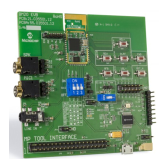
BM20 BLUETOOTH EVALUTATION BOARD USER’S GUIDE 1.3 BM20 EVALUATION BOARD CONTENTS BM20 Evaluation Board contains the following components as shown in Figure 1-1 which describes the evaluation board’s interfaces and connectors. Table 1-1 describes the various components of the evaluation board. - Page 8 L channel signal to external AMP. P0_1 P2_4 5V power for external AMP from USB. External AMP Connector (JP26) Battery connector (JP20) and Jack (JP19) (Alternative for BAT_IN) Description Description EXT_AMP_EN BAT_IN SPKR AGND SPKL AMP_POWER 2015 Microchip Technology Inc. Preliminary Edition page 8...
- Page 9 Status LEDs Red and Blue LEDs show the pairing/connection status MFB Button Switch to turn on/off BM20 module (SW7; Button 0 in UI) Play/Pause Button Button to play or pause the audio playback (SW8; Button1 in UI) Previous Track Button Button to skip track backwards (SW4;...
-
Page 10: Getting Started
2.2.2 USING THE EVALUATION BOARD 1. Connect Li-Ion batteries to JP20 or JP19. 2. Click MFB button to turn-on and enter pairing mode. The status LEDs will blink. Now the BM20 Evaluation board should be discoverable. 3. Turn on Bluetooth device manager on a host device (PC or smartphone), the host device will display a list of discoverable Bluetooth devices. - Page 11 Start / stop playing the current track. FIGURE 1-2: BM20 EVALUATION BOARD AUDIO CONTROL BUTTONS FIGURE 1-3: BM20 EVALUATION BOARD WITH EXTERNAL CLASS-D AMPLIFIER (It need modify the setting in UI to support external amplifier) 2015 Microchip Technology Inc.
- Page 12 2. Connect BM20 evaluation board to a smartphone that supports the A2DP and HFP/HSP Bluetooth profiles. 3. From another one phone, initiate a call to the smartphone that is paired with BM20 evaluation board. The A2DP stream pauses and the ringtone plays on the headset.
-
Page 13: Software/Utility Requirements
BM20 BLUETOOTH EVALUTATION BOARD USER’S GUIDE 2.4 SOFTWARE/UTILITY REQUIREMENTS 2.4.1 UI SETTING Step1. Open UI tool Step2. Firstly, you can load default UI setting or previous setting file. 2015 Microchip Technology Inc. Preliminary Edition page 13... - Page 14 Step3. Click “Edit” to modify the settings meet your needs. Step4. In the main settings, it can enable or disable supported profile or function which system need. Click “Next” for other setting. 2015 Microchip Technology Inc. Preliminary Edition page 14...
- Page 15 Step5. You can do system and functional setting in these pages. Click “Help” you can get more detail information. Step6. After finish parameter set up, click “Finish” button and a message will remind you check EEPROM size on your system. 2015 Microchip Technology Inc. Preliminary Edition page 15...
- Page 16 Step7. Click “Save” button to save these UI parameter as a “.txt” file Step8. We will use MPET tool to merge it with EEPROM table and use EEPROM tool load these parameter to system. 2015 Microchip Technology Inc. Preliminary Edition page 16...
- Page 17 2.4.2 DSP TOOL SETTING Step1. Open DSP tool Step2. Select IC version “ “IS2020_XXX_SHS ” (XXX is the version of chip, e.g. IS2020S-203) You can setup all voice and audio function in these pages. Step3. 2015 Microchip Technology Inc. Preliminary Edition page 17...
- Page 18 Step4. Click “Save” button to save these DSP parameter as a “.txt” file after finish all DSP setting. Then use MPET tool to merge it with EEPROM table and use EEPROM tool load these parameter to system. 2015 Microchip Technology Inc. Preliminary Edition page 18...
- Page 19 EVALUTATION BOARD USER’S GUIDE 2.4.3 MERGE TOOL SETTING Step1. Open MPET tool, click “Next” to set up. Step2. Select “UI Patch Only” to use full EEPROM table to merge UI and DSP parameter. 2015 Microchip Technology Inc. Preliminary Edition page 19...
- Page 20 “pull down” button to add them to merge list. If you want to add new parameter (e.g. UI and DSP parameter), click “+” button to add these files into tool for merge with EEPROM table. 2015 Microchip Technology Inc. Preliminary Edition...
- Page 21 BM20 BLUETOOTH EVALUTATION BOARD USER’S GUIDE Step5. Select an output path and create a name for the merged EEPROM table. Step6. Click “Generate” button to generate the new EEPROM table. 2015 Microchip Technology Inc. Preliminary Edition page 21...
- Page 22 BM20 BLUETOOTH EVALUTATION BOARD USER’S GUIDE Select if you want use new setting of these parts. Step7. Step8. Now you have a merged patch file (*.ipf file). 2015 Microchip Technology Inc. Preliminary Edition page 22...
- Page 23 Step 2. Connect EVB “P1” port and PC by USB cable. LED1 & LED2 on EVB will keep lighting. Step 3. Run the E2PROM_tool.exe program and a window will be come up as below 2015 Microchip Technology Inc. Preliminary Edition...
- Page 24 Step6. Press” Write” to write these setting to EEPROM Step7. After finish data update, remove USB cable and make SW12 to “ROM APP” mode and reboot. Now EVB can use the new setting after updated EEPROM parameter. 2015 Microchip Technology Inc. Preliminary Edition page 24...
-
Page 25: Module Configuration
Switch 12 PIN Definition 1: ON (P2_0: LOW) Test Mode 2: OFF (P2_4: HIGH) 3: ON (EAN: HIGH) 1: OFF (P2_0: HIGH) Application Mode 2: OFF (P2_4: HIGH) 3: ON (EAN: HIGH) 2015 Microchip Technology Inc. Preliminary Edition page 25... -
Page 26: Appendix A. Bm20 Audio Evaluation Board Schematics
BM20 BLUETOOTH EVALUTATION BOARD USER’S GUIDE APPENDIX A. BM20 AUDIO EVALUATION BOARD SCHEMATICS EVB block diagram 2015 Microchip Technology Inc. Preliminary Edition page 26... - Page 27 BM20 BLUETOOTH EVALUTATION BOARD USER’S GUIDE 2015 Microchip Technology Inc. Preliminary Edition page 27...
- Page 28 BM20 BLUETOOTH EVALUTATION BOARD USER’S GUIDE 2015 Microchip Technology Inc. Preliminary Edition page 28...
- Page 29 BM20 BLUETOOTH EVALUTATION BOARD USER’S GUIDE 2015 Microchip Technology Inc. Preliminary Edition page 29...
- Page 30 BM20 BLUETOOTH EVALUTATION BOARD USER’S GUIDE 2015 Microchip Technology Inc. Preliminary Edition page 30...
- Page 31 BM20 BLUETOOTH EVALUTATION BOARD USER’S GUIDE 2015 Microchip Technology Inc. Preliminary Edition page 31...
-
Page 32: Appendix B. Class D Amplifier Daughter Board
EVALUTATION BOARD USER’S GUIDE APPENDIX B. CLASS D AMPLIFIER DAUGHTER BOARD BM20 EVB reserves an interface (JP26) to connect with an external class D amplifier daughter board for speaker application demonstration. Here is a daughter board example of NAU8223 3.1W class D amplifier. - Page 33 BM20 BLUETOOTH EVALUTATION BOARD USER’S GUIDE 2015 Microchip Technology Inc. Preliminary Edition page 33...
- Page 34 Tel: 86-29-8833-7252 Tel: 631-435-6000 Fax: 86-29-8833-7256 San Jose, CA China - Xiamen Tel: 408-735-9110 Tel: 86-592-2388138 Canada - Toronto Fax: 86-592-2388130 Tel: 905-673-0699 China - Zhuhai Fax: 905-673-6509 Tel: 86-756-3210040 Fax: 86-756-3210049 Advance Information 2015 Microchip Technology Inc. page 33...
Need help?
Do you have a question about the BM20 and is the answer not in the manual?
Questions and answers