Table of Contents
Advertisement
Introduction
The BM71-XPro board is a hardware platform designed to evaluate and test the capabilities of the BM71 Bluetooth
RF module. The BM71-XPro board provides multiple options for rapid prototyping and developing applications. The
board is supported by Atmel Studio, an integrated development platform, which provides predefined applications and
examples.
Features
•
USB-UART Bridge (MCP2200) for Host PC Operation
•
On Board 3.3V LDO for Power Regulation
•
On Board SPI Flash for Storing Firmware Images (DFU OTA)
•
Test Point for GPIO Pin (P1_3)
•
Reset Push Button
•
DIP Switch to Control:
– BM71 operation mode
– LED
– GPIO pin
•
Passive RC Filters for PWM and ADC Inputs
•
Atmel Studio (ASF3), to Provide Predefined Application Examples
•
XPRO Extension Header
•
Header Pins for Current Measurement
•
Two Power Sources:
– Micro USB
– XPRO Connector
©
2019 Microchip Technology Inc.
BM70/71 XPro User's Guide
BM71-XPro
DS50002891A-page 1
®
Advertisement
Table of Contents

Related Manuals for Microchip Technology BM71-XPro


Summary of Contents for Microchip Technology BM71-XPro
-
Page 1: Introduction
Introduction ® The BM71-XPro board is a hardware platform designed to evaluate and test the capabilities of the BM71 Bluetooth RF module. The BM71-XPro board provides multiple options for rapid prototyping and developing applications. The board is supported by Atmel Studio, an integrated development platform, which provides predefined applications and examples. -
Page 2: Table Of Contents
Connecting the BM71 XPRO to MBD App in Auto Mode............. 7 3.2. Configuring the BM71 Module to Operate in Manual Mode (Host PC)........10 3.3. Connecting the BM71-XPro to MBD App in Manual Mode (Host PC)........14 3.4. Using the BM70/71 MCU drivers....................23 Appendix A. Updating the BM71 Module Firmware................27 Appendix B. -
Page 3: Kit Contents
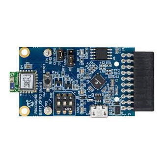
BM71-XPro Kit Contents Kit Contents The following figure shows the layout of the BM71-XPro board and illustrates the components available in the board: Figure 1-1. BM71-XPro Board BM71 LED USB-UART Bridge (MCP200) Power Supply Selection Header On board SPI Flash Current Measurement Header... -
Page 4: Hardware Features
The headers have a pitch of 2.54 mm. For details on the operating the BM71-XPro via a host MCU Xplained Pro board, refer to 3.3 Connecting the BM71-XPro to MBD App in Manual Mode (Host... -
Page 5: Dip Switch
Current Measurement Header A J3 header can be used for current measurement.. All power to the BM71-XPro is routed through these header pins. To measure the power consumption of the module, remove the jumper and replace it with an ammeter. To make sure only the power consumption of the BM71 module is measured, turn off the blue LED using switch #2 of the DIP switch. - Page 6 Xplained Pro Extension Header SPI signals to the External SPI Flash if the product causes emissions above the permissible limits of the standard. For reference for the BM71 module placement and layout guidelines please refer the BM71 Module datasheet. DS50002891A-page 6 © 2019 Microchip Technology Inc.
-
Page 7: Module Configuration
1.4. Switch 2 (blue LED) on the DIP switch is set to ON. Connect the BM71-XPro board to a host PC using the mini-USB cable. Ensure that green LED (LD1) is solid ON indicating USB power. Connect BM71-XPro to a PC host using micro-USB cable. - Page 8 On Dashboard, select “BM70”, see the following figure. Figure 3-2. MBD Dashboard In the follow-up screen, click Scan and “Scan” again at the bottom. Once the scanning process completes, the BM71 module should appear as “BM71_BLE” by default. DS50002891A-page 8 © 2019 Microchip Technology Inc.
- Page 9 BM71 module should show up. Figure 3-4. MBD Connecting to BM71 XPRO 10. Click on “Transfer data to device”. The Transparent UART screen should open (see following figure). The data pipe is now open. DS50002891A-page 9 © 2019 Microchip Technology Inc.
-
Page 10: Configuring The Bm71 Module To Operate In Manual Mode (Host Pc)
1.3. Switch 2 (blue LED) on the DIP switch is set to ON. Connect the BM71-XPro board to the host PC using the mini-USB cable. Ensure that the green LED (LD1) is solid ON indicating USB power. Connect BM71-XPro board to the host PC using micro-USB cable. Verify the virtual COM port is enumerated on the host PC. - Page 11 In the ‘Loading Option’ dialog box, select “Load Text File” option (see the following figure) Figure 3-7. Loading Option In the file browser, select “IS1871SF_102_BLEDK3v1.11_UI v1.00(BM71)_default.txt” In the UI tool dialog box, click on “Edit” DS50002891A-page 11 © 2019 Microchip Technology Inc.
- Page 12 Set the UART_RX_IND (Low power operation) to ‘Disable’ from the drop-down menu. 10.2. Set the Operation mode to “Manual Pattern” under the ‘Operation mode setting’ section. 11. Click ‘Finish’ 12. In the UI Tool, click ‘Write’ (see following figure) DS50002891A-page 12 © 2019 Microchip Technology Inc.
- Page 13 13. In the ‘Read/Write Flash’ dialog box, select an appropriate COM port and click on ‘Write’. In the confirmation window, click ‘Yes’ to update EFLASH. Figure 3-10. Read / Write Flash 14. After the successful Flash write, a confirmation message will be flashed as shown in the following figure. DS50002891A-page 13 © 2019 Microchip Technology Inc.
-
Page 14: Connecting The Bm71-Xpro To Mbd App In Manual Mode (Host Pc)
1.4. Switch 2 (blue LED power) on the DIP switch is set to ON. Connect the BM71-XPro board to the host PC using the mini-USB cable. Ensure that green LED (LD1) is solid ON indicating USB power. Connect BM71-XPro to the host PC using micro-USB cable. Verify the virtual COM port is enumerated on host PC. - Page 15 Command’ section, select ‘0x01: Read Local Information’ for the ‘Opcode’ field. Click ‘Send’ (see following figure). The module will respond with the Bluetooth MAC address, firmware version and hardware version. The response is shown in the “Log view” window. DS50002891A-page 15 © 2019 Microchip Technology Inc.
- Page 16 Select “0x01: Enter Standby Mode” for the Standby mode field. 7.3. Click “Send”. Once the module enters the Standby mode (started advertising), the BT Status field will be updated (see the following figure). DS50002891A-page 16 © 2019 Microchip Technology Inc.
- Page 17 BM71-XPro Module Configuration Figure 3-14. Start Advertising Open the MBD app on the phone/tablet. Ensure that the Bluetooth is turned ON in the device. 10. On Dashboard, select “BM70”, see the following figure. DS50002891A-page 17 © 2019 Microchip Technology Inc.
- Page 18 12. Once the scanning process completes, the BM71 module should appear as “BM71_BLE” by default. Figure 3-16. MBD Scanning Process 13. Click on the “BM71_BLE” to start a connection process. Once connected, the transparent UART service available on the BM71 module should show up. DS50002891A-page 18 © 2019 Microchip Technology Inc.
- Page 19 BM71-XPro Module Configuration Figure 3-17. MBD Connecting to BM71-XPro 14. The manual tool should show the connection details once the connection from the peer device (phone/tablet) is successfully executed (see the following figure). DS50002891A-page 19 © 2019 Microchip Technology Inc.
- Page 20 15. On the MBD app, click on “Transfer data to device”. The Transparent UART screen should open. Ensure that the ‘Write with Response’ in the app is set to ON. The data pipe is now open. DS50002891A-page 20 © 2019 Microchip Technology Inc.
- Page 21 BM71-XPro Module Configuration Figure 3-19. MBD Data Pipe 16. The manual tool should provide the message for the data pipe in the log view (see following figure). DS50002891A-page 21 © 2019 Microchip Technology Inc.
- Page 22 Figure 3-20. Open a Transparent UART Data Pipe 17. Go to the ‘Transparent’ tab on the manual tool. Check operation of the data pipe, by entering data in the app or in the ‘Send Data’ field in the manual tool. DS50002891A-page 22 © 2019 Microchip Technology Inc.
-
Page 23: Using The Bm70/71 Mcu Drivers
• SAML21 Xplained Pro board. • BM71-XPro board. To use the BM71 MCU drivers in ASF3, the BM71-XPro board needs to be connected to EXT1 header of the BM71- XPro board (see following figure). DS50002891A-page 23 © 2019 Microchip Technology Inc. - Page 24 Module Configuration Figure 3-22. BM71-XPro Board Connected to the SAML21 Xplained Pro Connect to the BM71-XPro board to EXT1 header of the SAML21 Xplained Pro board. Open Atmel Studio software. On the top menu, select ‘File’ → ‘New’ → ‘Example Project’.
- Page 25 BM71-XPro Module Configuration Figure 3-23. Opening an Example Project for BM71-XPro Board The list of available example projects is provided. Select any project to get started. In the preceding figure, the iBeacon was selected as an example. Click OK in the succeeding dialog box to accept the terms and conditions.
- Page 26 Figure 3-24. Solution Explorer window in Atmel Studio Note: For more instructions on executing the project, click on the ‘iBeacon_Demo_Getting_Started_Guide.pdf’ file for details. Follow the instructions in the getting started guide to build, load, and test the project. DS50002891A-page 26 © 2019 Microchip Technology Inc.
-
Page 27: Appendix A. Updating The Bm71 Module Firmware
Connect the BM71-XPro board to the host PC using the micro-USB cable. Verify that swtich#1 of the DIP switch (SW2) is set to ON position. Press Reset button (SW1) and verify that the blue LED (LD4) is solid ON indicating that the BM71 is in Memory Programming mode. -
Page 28: Appendix B. Schematics And Bill Of Materials
BM71-XPro Appendix B. Schematics and Bill of Materia... Appendix B. Schematics and Bill of Materials The schematic and the Bill of Materials (BOM) for the BM71-XPro board are provided below. DS50002891A-page 28 © 2019 Microchip Technology Inc. - Page 29 BM71-XPro Appendix B. Schematics and Bill of Materia... IO_BUS HCI_BUS DS50002891A-page 29 © 2019 Microchip Technology Inc.
- Page 30 BM71-XPro Appendix B. Schematics and Bill of Materia... DS50002891A-page 30 © 2019 Microchip Technology Inc.
- Page 31 BM71-XPro Appendix B. Schematics and Bill of Materia... DS50002891A-page 31 © 2019 Microchip Technology Inc.
- Page 32 BM71-XPro Appendix B. Schematics and Bill of Materia... DS50002891A-page 32 © 2019 Microchip Technology Inc.
-
Page 33: Agency Certification
PARLIAMENT AND OF THE COUNCIL" of 16 April 2014. SIMPLIFIED EU DECLARATION OF CONFORMITY Hereby, Microchip Technology Inc. declares that the radio equipment type [A09-3110] is in compliance with Directive 2014/53/EU. The full text of the EU declaration of conformity is available at the following internet address (refer product specific pages): http://www.microchip.com/design-centers/wireless-connectivity/. -
Page 34: Document Revision History
BM71-XPro Document Revision History Document Revision History Revision Date Section Description 07/2019 Document Initial Revision DS50002891A-page 34 © 2019 Microchip Technology Inc. -
Page 35: The Microchip Website
Information contained in this publication regarding device applications and the like is provided only for your convenience and may be superseded by updates. It is your responsibility to ensure that your application meets with DS50002891A-page 35 © 2019 Microchip Technology Inc. -
Page 36: Trademarks
The Adaptec logo, Frequency on Demand, Silicon Storage Technology, and Symmcom are registered trademarks of Microchip Technology Inc. in other countries. GestIC is a registered trademark of Microchip Technology Germany II GmbH & Co. KG, a subsidiary of Microchip Technology Inc., in other countries. -
Page 37: Worldwide Sales And Service
New York, NY Tel: 46-31-704-60-40 Tel: 631-435-6000 Sweden - Stockholm San Jose, CA Tel: 46-8-5090-4654 Tel: 408-735-9110 UK - Wokingham Tel: 408-436-4270 Tel: 44-118-921-5800 Canada - Toronto Fax: 44-118-921-5820 Tel: 905-695-1980 Fax: 905-695-2078 DS50002891A-page 37 © 2019 Microchip Technology Inc.
Need help?
Do you have a question about the BM71-XPro and is the answer not in the manual?
Questions and answers