Table of Contents
Advertisement
Quick Links
BM83 Bluetooth
Introduction
The BM83 Bluetooth Audio Development Board (BM83 EVB) enables the user to evaluate and demonstrate the
functionality of the BM83 audio module and IS2083BM System-on-Chip (SoC). This board is a complete, all-in-one
solution to develop multiple Bluetooth audio applications including portable speakers and headphones. The BM83
EVB features an on-board PIC32 for Host MCU mode applications, an external codec to improve audio quality, a
digital microphone to capture voice audio, indicator LEDs and buttons for ease of development.
In addition to the BM83 EVB, the IS2083 SDK and IS208x_Config_GUI_Tool (Config Tool) are provided to customize
the audio processing settings.
Features
•
BM83 module, qualified for Bluetooth 5.0 specifications
•
On-board microcontroller (PIC32MX450F256L) for easy operation and feature demonstration
•
Plug-in module (PIM) socket for external microcontroller (MCU)
•
STMicroelectronics codec (STA369BW) Daughter Board
•
Digital Microphone (Knowles' SPH0641LU4H-1) Daughter Board
•
J-Link 6-Pin Adapter Board for IS2083BM debugging
•
On-board keypad matrix (audio control buttons) that can be controlled either by the BM83 module or the on-
board PIC32 MCU, which makes it easy for playback control
•
Aux-in, MIC-In, and Stereo out ports
•
On-board thermistor
•
2 LEDs for the Bluetooth subsystem and various other LEDs configurable by the on-board MCU
•
JTAG program/debug port, USB to UART port, XPRO header interfaces
•
Li-ion battery connector, 15V DC power jack and USB power source
©
2019 Microchip Technology Inc.
®
Audio Development Board User's Guide
User Guide
BM83 EVB
DS50002902A-page 1
Advertisement
Table of Contents

Related Manuals for Microchip Technology BM83 EVB


Summary of Contents for Microchip Technology BM83 EVB
-
Page 1: Introduction
EVB features an on-board PIC32 for Host MCU mode applications, an external codec to improve audio quality, a digital microphone to capture voice audio, indicator LEDs and buttons for ease of development. In addition to the BM83 EVB, the IS2083 SDK and IS208x_Config_GUI_Tool (Config Tool) are provided to customize the audio processing settings. -
Page 2: Table Of Contents
Firmware Update over USB ...................... 23 Customizing Module Parameters......................28 6.1. Config Tool Setup........................28 Appendix A: BM83 EVB Reference Schematics................... 41 Appendix B: STA369BW Audio Daughter Board...................55 Appendix C: Digital Microphone Daughter Board................. 57 10. Appendix D: J-Link 6-Pin Adapter Board....................58 11. - Page 3 15. Document Revision History........................70 The Microchip Website..........................71 Product Change Notification Service......................71 Customer Support............................71 Microchip Devices Code Protection Feature....................71 Legal Notice..............................71 Trademarks..............................72 Quality Management System........................72 Worldwide Sales and Service........................73 User Guide DS50002902A-page 3 © 2019 Microchip Technology Inc.
-
Page 4: Quick References
IS2083 Reference Design Application Note Note: For a complete list of development support tools and documentation, visit http://www.microchip.com/BM83. Hardware Requirements ® • BM83 Bluetooth Audio Development Board (BM83 EVB) • BM83 module mounted on BM83 Carrier Board • Bluetooth-enabled smartphone: ™... -
Page 5: Acronyms/Abbreviations
Evaluation Board Field Effect Transistor General Access Profile GATT General Attribute Profile GFSK Gaussian Frequency Shift Keying GPIO General Purpose Input Output Graphical User Interface Hands-free Profile High Pass Filter Headset Profile User Guide DS50002902A-page 5 © 2019 Microchip Technology Inc. - Page 6 Pulse Density Modulation Plug-in Module Packet Loss Concealment Power Management Unit Power-on Reset Pulse Width Modulation Radio Frequency Receive Frame Sync RoHS Restriction of Hazardous Substances RSSI Received Signal Strength Indicator Receiver User Guide DS50002902A-page 6 © 2019 Microchip Technology Inc.
- Page 7 Synchronous Connection-oriented Software Development Kit Special Interest Group Signal-to-Noise Ratio System-on-Chip Serial Port Profile Software Transmitter UART Universal Asynchronous Receiver-Transmitter User Interface Universal Serial Bus Virtual Bass Enhancement Voltage-controlled Oscillator Watchdog Timer User Guide DS50002902A-page 7 © 2019 Microchip Technology Inc.
-
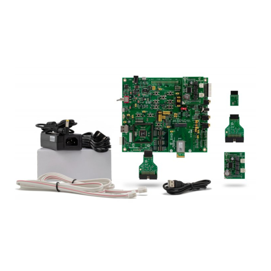
Page 8: Kit Overview
BM83 EVB Kit Overview Kit Overview This section provides an overview of the BM83 EVB. The following figure illustrates the top view of the BM83 EVB with its components. Figure 2-1. BM83 EVB Components 15V DC Adapter (P200) XPRO Header (J304) - Page 9 Micro-B USB Cable Power Cable Note: If any part of the BM83 EVB is missing, contact your Microchip sales office for assistance. A list of Microchip offices for sales and service is provided on the back page of this document.
-
Page 10: Hardware
BM83 EVB Hardware Hardware This chapter describes the hardware features of the BM83 EVB. The BM83 EVB includes a range of peripheral components. Figure 3-1. Block Diagram Adapter Li-Ion Power Battery Jack Mode Switch 12 MHz Crystal Regulator Regulator P3_4 BAT_IN... -
Page 11: Hardware Features
BM83 EVB Hardware Hardware Features The following sections provide detailed information on the BM83 EVB components. To locate these components in the BM83 EVB, refer to Figure 2-1 Figure 3-2. Figure 3-2. BM83 EVB Switches, LEDs, and Jumpers D600 JP304 D203... -
Page 12: Usb Connectivity
• SW711 – Select button (SEL), turns on the system and puts the system into Pairing mode during Host MCU mode application demonstration Note: To locate these switches and push buttons available on the BM83 EVB, refer to Figure 3-2. -
Page 13: Headers
BM83 EVB Hardware 3.1.5 Headers The following headers are available on the BM83 EVB. Note: To locate these headers available on the BM83 EVB, refer to Figure 2-1. 3.1.5.1 I2S Header I2S header (J405) provides the interface to connect an STA369BW Audio Daughter Board to the BM83 module. The following table provides the pin details of I2S header. -
Page 14: Audio Control Button Headers
Used for pairing the module with a smartphone (only for Host MCU mode) Not used Not connected To locate these headers on the BM83 EVB, refer to Figure 2-1. Table 3-6. Embedded Mode Audio Control Button Header Configurations (J700, J701, and J702) -
Page 15: Bm83 Carrier Board Interface
To locate these headers on the BM83 EVB, refer to Figure 2-1. 3.1.5.4 BM83 Carrier Board Interface The following table provides the pin details of J300 and the BM83 module interface with the BM83 EVB. Table 3-8. Carrier Board Interface (J300) Pin Details Pin Name Pin Number Pin Name... -
Page 16: Icsp Header
Clock (PGEC1) Not connected (NC) 3.1.5.6 Xplained PRO Header The BM83 EVB provides 20-pin XPRO header (J304) to interface with XPRO platform. The following table provides the pin details of XPRO header. Table 3-10. XPRO Header (J304) Pin Details Pin Name... -
Page 17: Digital Microphone Headers
3.1.5.7 Digital Microphone Headers The 5-pin digital microphone header provides an interface to BM83 EVB and the Digital Microphone Daughter Board. The pin description is provided in the following table. Table 3-11. Digital Microphone Headers (J1, J503, and J502) Pin Description... -
Page 18: Embedded Mode Quick Demo
This section provides a quick demo to stream audio using the BM83 module in Embedded mode. Perform the following steps: Note: The BM83 EVB is preconfigured for the Embedded mode quick demo. Unbox the kit and connect the speaker cables to the STA369BW Audio Daughter Board at CN1 and CN2, and connect the cables to the speaker. - Page 19 Press FWD button (SW707) to jump to next audio file. 8.6. Press REV button (SW708) to jump to previous audio file. 8.7. Press MFB button (SW701) for a minimum of 4-5 seconds to turn OFF the system. User Guide DS50002902A-page 19 © 2019 Microchip Technology Inc.
-
Page 20: Firmware Update
JP305 Mount a jumper on “3V3_IO” and “VDDIO” pins of JP305 J600 Connect the USB cable from a PC to J600 To locate these jumpers, switches, and power sources on the BM83 EVB, refer to Figure 3-2 Figure 2-1. Perform the following steps to load the firmware files onto the BM83 module using isUpdate tool. - Page 21 3. The message on console and the transition of Connect button to Disconnect indicates that the connection is established successfully between the PC and the BM83 module. Figure 5-2. Connection Established User Guide DS50002902A-page 21 © 2019 Microchip Technology Inc.
- Page 22 Note: The Embedded mode firmware images are available in the package, refer to http://www.microchip.com/ BM83. Figure 5-3. Browsing and Loading the Files Click Update to load the firmware to BM83 module and observe the progress. Figure 5-4. Updating the Firmware User Guide DS50002902A-page 22 © 2019 Microchip Technology Inc.
-
Page 23: Firmware Update Over Usb
Use the isUpdate tool to perform a firmware update on the BM83 module through USB Device Firmware Upgrade (DFU). The BM83 EVB should be in Application mode. For firmware update over the USB, the user must ensure the hardware settings and configurations described in the following table. - Page 24 Note: In isUpdate tool, image num value must be equal to the number of images to be programmed on the device. For example, to program firmware (image1), DSP (image2), and configuration (image3), the image num value must be selected as 3. User Guide DS50002902A-page 24 © 2019 Microchip Technology Inc.
- Page 25 Firmware Update The message on console and the transition of Connect button to Disconnect indicates that the connection is established successfully between the PC and the BM83 module. Figure 5-7. Connection Established User Guide DS50002902A-page 25 © 2019 Microchip Technology Inc.
- Page 26 Note: The Embedded mode firmware images are available in the package, refer to www.microchip.com/ BM83. Figure 5-8. Browsing and Loading the Files Click Update to update the firmware and observe the progress. User Guide DS50002902A-page 26 © 2019 Microchip Technology Inc.
- Page 27 BM83 EVB Firmware Update Figure 5-9. Updating the Firmware Click Disconnect and close the isUpdate tool after a successful firmware update. Figure 5-10. Process Completed 10. Remove the USB cable. User Guide DS50002902A-page 27 © 2019 Microchip Technology Inc.
-
Page 28: Customizing Module Parameters
To configure the GUI parameters, perform the following steps: 1. Open the Config Tool and click OK to configure the parameters. Figure 6-1. Config Tool - Welcome Window 2. In the Config Tool, click Load. Figure 6-2. Config Tool User Guide DS50002902A-page 28 © 2019 Microchip Technology Inc. - Page 29 Open, see the following figure. Figure 6-3. Loading Default GUI Parameters 4. After loading the GUI parameters, click Edit to customize the GUI parameters on the Main Feature window. Figure 6-4. Editing Parameters User Guide DS50002902A-page 29 © 2019 Microchip Technology Inc.
- Page 30 “Embedded Mode” option (see Figure 6-5) and click Next. Note: • For Host MCU mode, select the “Host MCU Mode”. • For Embedded mode, select the “Embedded Mode”. Figure 6-5. Main Feature Settings User Guide DS50002902A-page 30 © 2019 Microchip Technology Inc.
- Page 31 6. In the System and Functional Settings window, go to Sys. Setup1 tab to power ON/OFF the Bluetooth system. Select MFB Power ON/OFF in the “Power Switch Type” section. Figure 6-6. Options in Sys. Setup1 Tab User Guide DS50002902A-page 31 © 2019 Microchip Technology Inc.
- Page 32 Device name – add the device name in the text box available under “Name Frag Segment” section. • Pairing mechanism – select Enable for the pairing mechanism available under “Simple Pairing” drop-down menu. Figure 6-7. Options in Sys. Setup2 Tab User Guide DS50002902A-page 32 © 2019 Microchip Technology Inc.
- Page 33 BM83 EVB Customizing Module Parameters 8. In the CODEC Setup tab, select Internal codec from the “CODEC Output Type” drop-down menu. Figure 6-8. Options in CODEC Setup Tab User Guide DS50002902A-page 33 © 2019 Microchip Technology Inc.
- Page 34 BM83 EVB Customizing Module Parameters 9. Click Finish after modifying these settings. IS208x_DSP_GUI_Tool window opens as shown in the following figure. Figure 6-9. Main Function Tab User Guide DS50002902A-page 34 © 2019 Microchip Technology Inc.
- Page 35 BM83 EVB Customizing Module Parameters 10. In the Voice Function tab, the user can set the required parameters as highlighted in the following figure. Figure 6-10. Voice Function Tab User Guide DS50002902A-page 35 © 2019 Microchip Technology Inc.
- Page 36 BM83 EVB Customizing Module Parameters 11. In the Audio Function tab, the user can set the required parameters as highlighted in the following figure. Figure 6-11. Audio Function Tab User Guide DS50002902A-page 36 © 2019 Microchip Technology Inc.
- Page 37 BM83 EVB Customizing Module Parameters 12. In the I2S/PCM tab, the user can set the required parameters as highlighted in the following figure. Figure 6-12. I2S/PCM Tab User Guide DS50002902A-page 37 © 2019 Microchip Technology Inc.
- Page 38 BM83 EVB Customizing Module Parameters 13. Click Save to save the changed parameters onto a file and click OK on the confirmation window (see the following figure). Figure 6-13. Saving Parameters User Guide DS50002902A-page 38 © 2019 Microchip Technology Inc.
- Page 39 BM83 EVB Customizing Module Parameters 14. Click Save to save the file in .HEX format as shown in the following figure. Figure 6-14. Save as a HEX File User Guide DS50002902A-page 39 © 2019 Microchip Technology Inc.
- Page 40 After saving the file, the user can see an additional .hex file in the GUI tool folder as shown in the following figure. Figure 6-16. Generated HEX File Note: For Embedded mode with internal codec demo, refer to 14. Appendix H: Bluetooth Audio Demonstration in Embedded Mode with Internal Codec. User Guide DS50002902A-page 40 © 2019 Microchip Technology Inc.
-
Page 41: Appendix A: Bm83 Evb Reference Schematics
BM83 EVB Appendix A: BM83 EVB Reference Schematics Appendix A: BM83 EVB Reference Schematics Figure 7-1. USB Connector Schematic USB CONNECTOR USB2.0 MICRO-B FEMALE 5V_BT J200 BM83 Carrier Board USB TP LOOP Red TP203 VBUS R206 R207 0603 FB200 0603 C211 C212 0.1uF... - Page 42 BM83 EVB Appendix A: BM83 EVB Reference Schematics Figure 7-3. 5V Power Switch 5V POWER SWITCH 5V_DC 5V_ADAP_IN SW200 TP LOOP Red 5V_DC TP204 5V_USB TOGGLE SPDT NOTE: 5V_USB R208 Input Range for C213 C214 D205 ADAP_IN : 4.6V to 6V Recommended to switch to 0.1uF...
- Page 43 BM83 EVB Appendix A: BM83 EVB Reference Schematics Figure 7-5. Reset IC RESET IC (OPTIONAL) VDD_IO R307 SYS_PWR 4.7k U300 0603 RST_N VOUT RST_N C301 MCP111 0.1uF 0603 Figure 7-6. Reset RESET SW700 RST_N RST_N TACT SPST D700 C700 PESD5V0S1BA 15pF SOD-323...
- Page 44 BM83 EVB Appendix A: BM83 EVB Reference Schematics Figure 7-7. Push Button Interface PUSH BUTTON SYS_PWR R700 MFB/Power 0603 VOL+ PAIRING SW701 SW702 SW703 VOL_UP PAIRING TACT SPST TACT SPST TACT SPST D701 D702 C701 D703 PESD5V0S1BA PESD5V0S1BA C702 C703 15pF...
- Page 45 BM83 EVB Appendix A: BM83 EVB Reference Schematics Figure 7-8. PIM Socket 100 Pin PIM Socket 3V3_PIC 3V3_PIC U400 RG15 RPE3 RG13 RG12 RG14 MCU_IC_N MCU_BCLK MCU_SDI MFB_MCU MCU_SDO PIM_MCLR MCU_P20 C409 MCU_EXT8 10uF MCU_EXT7 PAIRING_MCU RTSn_MCU 0805 MCU_PROT_N MCU_EXT6 MCU_REC...
- Page 46 BM83 EVB Appendix A: BM83 EVB Reference Schematics Figure 7-9. Microphone MICROPHONE INPUT MIC_BIAS R500 2.2k MIC1 0603 C500 C502 MIC_P1 JP500 0603 0603 C504 0603 HDR-2.54 Male 1x3 C506 P500 JACK Stereo Phone 3.5mm MIC_N1 0603 R505 0603 TP500 MIC_P1...
- Page 47 BM83 EVB Appendix A: BM83 EVB Reference Schematics Figure 7-10. MCU to Bluetooth Switch MCU to BT Switch SW402 R416 0603 MFB_MCU R417 0603 TXD_MCU HCI_RXD R418 0603 RXD_MCU HCI_TXD R419 0603 RST_MCU RST_N R420 0603 UTX_IND P0_0 R422 0603 CTSn_MCU...
- Page 48 BM83 EVB Appendix A: BM83 EVB Reference Schematics Figure 7-11. PIC32MX450F256L Pin Configuration C408 10uF 0805 MFB_MCU MFB_MCU MCU_IC_N MCU_IC_N 3V3_PIC U402 RG15 RG15 RC14 3V3_PIC SOSCO/RPC14/T1CK/RC14 RC13 AN22/RPE5/PMD5/RE5 SOSCI/RPC13/RC13 MCU_EXT1 AN23/PMD6/RE6 RPD0/INT0/RD0 MCU_EXT1 RD11 AN27/PMD7/RE7 RPD11/PMCS1/RD11 SCK1 RPC1/RC1 RPD10/SCK1/PMCS2/RD10 RPD9...
- Page 49 BM83 EVB Appendix A: BM83 EVB Reference Schematics Figure 7-12. LED Interface 3V3_GEN LED(MCU) D401 R406 MCU_LED1 200R GREEN 0603 D402 R409 MCU_LED2 200R GREEN 0603 D403 R411 MCU_LED3 200R GREEN 0603 D404 R412 MCU_LED4 200R GREEN 0603 D405 R413 MCU_LED5...
- Page 50 BM83 EVB Appendix A: BM83 EVB Reference Schematics Figure 7-13. ICSP Interface JP402 Shunt 2.54mm 1x2 3V3_PIC MCU S-Flash 3V3_GEN 3V3_PIC 3V3_PIC U401 C410 3V3_PIC R403 HOLD 0.1uF FLASH_CS# C411 JP400 MCU_BCLK 10uF 0603 HDR-2.54 Male 1x2 MCU_SDO 0603 MCU_SDI 0805...
- Page 51 BM83 EVB Appendix A: BM83 EVB Reference Schematics Figure 7-15. I2C Interface I2C_INTERFACE I2C_INTERFACE 3V3_IO 3V3_IO 3V3_IO 3V3_IO JP309 JP309 Note: Note: P2_3 P2_3 JP309 is Test Point for SW I2C IOs. JP309 is Test Point for SW I2C IOs. P2_3...
- Page 52 BM83 EVB Appendix A: BM83 EVB Reference Schematics Figure 7-18. CPU JTAG Header 3V3_IO CPU_JTAG J301 RST_N EMUD_CPU P1_2 C311 EMUC_CPU P1_3 0.1uF 0603 HDR-2.54 Male 1x6 Figure 7-19. XPRO Header XPRO_INTERFACE Xplained Pr o standard extension header J304 ADC+ ADC- HOST_WAKEUP...
- Page 53 BM83 EVB Appendix A: BM83 EVB Reference Schematics Figure 7-21. Stereo AUX Line Input, Audio Headset Output, Audio Board Interface AUDIO HEADSET OUTPUT STEREO AUX LINE INPUT AOHPM JP505 JP501 D500 C515 R507 HDR-2.54 Male 1x2 Shunt 2.54mm 1x2 0603 R501 0.1uF...
- Page 54 BM83 EVB Appendix A: BM83 EVB Reference Schematics Figure 7-23. 5V to 3V3 Generation for USB-UART Section 5V TO 3V3 GENERATION 5V_MCP EXT_3V3 U600 MCP1702T-3302E/CB VOUT C602 C603 C604 0.1uF 0.1uF 10uF 0603 0603 0603 User Guide DS50002902A-page 54 © 2019 Microchip Technology Inc.
-
Page 55: Appendix B: Sta369Bw Audio Daughter Board
The following table provides the pin description of Audio Daughter Board headers. Table 8-1. 20-Pin Audio Daughter Board Header (J1) Pin Details Pin Name Pin Number Pin Name UART_RXD UART_CTS UART_TXD UART_RTS I2C_SCL I2C_SDA I2S_RFS1 I2S_DR1 I2S_SCLK1 I2S_DT1 I2S_MCLK1 User Guide DS50002902A-page 55 © 2019 Microchip Technology Inc. - Page 56 Appendix B: STA369BW Audio Daughter Board ...continued Pin Name Pin Number Pin Name Table 8-2. 12-Pin Audio Daughter Board Header (J2) Pin Details Pin Name Pin Number Pin Name DSP_IRQ_N PWRDN MUTE_N User Guide DS50002902A-page 56 © 2019 Microchip Technology Inc.
-
Page 57: Appendix C: Digital Microphone Daughter Board
BM83 module supports 1 stereo Digital Microphone (left and right) terminated at J503 and J502 headers respectively. The VDD power supply for Digital Microphone operation is provided over J509 header on the BM83 EVB. The Select pin should not be left floating and should be connected to high or low. This is achieved by 3-pin headers J505 and J504 on BM83 EVB. -
Page 58: Appendix D: J-Link 6-Pin Adapter Board
Appendix D: J-Link 6-Pin Adapter Board J-Link 6-Pin Adapter Board is designed to connect to its targets through a 20-pin cable, provided with the J-Link. However, BM83 EVB uses a 6-pin connector supporting 2-wire JTAG. Figure 10-1. J-Link 6-Pin Adapter Board The following table provides the pin description of J-Link 6-Pin Adapter Board. -
Page 59: Appendix E: Updating Pic32 Mcu Parameters
Note: Download and install the latest version of MPLAB X IDE tool, which is available at www.microchip.com/ mplab/mplab-x-ide. Open the MPLAB X IPE tool. Under the Device drop-down menu, select the MCU (PIC32MX450F256L) that is present on the BM83 EVB. The red dot indicates that the selected device does not match. User Guide DS50002902A-page 59 ©... - Page 60 Figure 11-3. Search for On-board Microcontroller After the connection is established, click Browse and locate the MCU firmware file from the software folder. Then click Program as shown in the following figure. User Guide DS50002902A-page 60 © 2019 Microchip Technology Inc.
- Page 61 BM83 EVB Appendix E: Updating PIC32 MCU Parameters Figure 11-4. Connect and Program User Guide DS50002902A-page 61 © 2019 Microchip Technology Inc.
- Page 62 After the programming is complete, observe the Output – IPE window on the console. Note: MCU firmware version V1.4.1 is used for the demonstration. Figure 11-5. Verify the Log 10. Remove the 15V adapter. User Guide DS50002902A-page 62 © 2019 Microchip Technology Inc.
-
Page 63: Appendix F: Hardware Setup For Application Demo In Host Mcu Mode
BM83 module and driving the I2S audio out from the BM83 to an STA369BW Audio Daughter Board. Perform the following hardware changes for the Host MCU mode application demo: Note: To locate these switches, jumpers, and headers on the BM83 EVB, refer to Figure 2-1 Figure 3-2. -
Page 64: Host Mcu Mode Quick Demo
Connect the speakers to the STA369BW Audio Daughter Board at CN1 and CN2. Figure 12-1. Speakers Connected to the STA369BW Audio Daughter Board The SW200 switch is set to 5V_USB position as shown in the following figure. Figure 12-2. SW200 Switch Position User Guide DS50002902A-page 64 © 2019 Microchip Technology Inc. - Page 65 Select the module device name "BM83" from the scan results. Pair and then connect the device. 7.3. On successful pairing, see the device name with status as Connected. Note: This demonstration uses the EA1 demo version of the firmware. User Guide DS50002902A-page 65 © 2019 Microchip Technology Inc.
- Page 66 Press FWD button (SW707) to jump to next audio file. 8.6. Press REV button (SW708) to jump to previous audio file. 8.7. Press SEL button (SW711) to turn OFF the system. User Guide DS50002902A-page 66 © 2019 Microchip Technology Inc.
-
Page 67: Appendix G: Hardware Setup For Application Demo In Embedded Mode
Board. The BM83 module is connected to the external codec over I2S and I2C. Perform the following hardware changes for the Embedded mode application demo. Note: To locate these switches, jumpers, and headers on the BM83 EVB, refer to Figure 2-1 Figure 3-2. - Page 68 With the above settings, the user can plug in the 15V DC adapter and perform the application demo in Embedded mode with the appropriate firmware image. This firmware image for the Embedded mode is available at www.microchip.com/BM83. User Guide DS50002902A-page 68 © 2019 Microchip Technology Inc.
-
Page 69: Appendix H: Bluetooth Audio Demonstration In Embedded Mode With Internal Codec
6.1 Config Tool Setup. In this demonstration, the user can stream audio on the BM83 EVB using a smartphone. Perform the following hardware settings on the BM83 EVB for Embedded mode with internal codec audio demo after updating the firmware: Turn OFF the SW300 switch. -
Page 70: Document Revision History
BM83 EVB Document Revision History Document Revision History Revision Date Section Description 07/2019 Document Initial Revision User Guide DS50002902A-page 70 © 2019 Microchip Technology Inc. -
Page 71: The Microchip Website
Information contained in this publication regarding device applications and the like is provided only for your convenience and may be superseded by updates. It is your responsibility to ensure that your application meets with User Guide DS50002902A-page 71 © 2019 Microchip Technology Inc. -
Page 72: Trademarks
The Adaptec logo, Frequency on Demand, Silicon Storage Technology, and Symmcom are registered trademarks of Microchip Technology Inc. in other countries. GestIC is a registered trademark of Microchip Technology Germany II GmbH & Co. KG, a subsidiary of Microchip Technology Inc., in other countries. -
Page 73: Worldwide Sales And Service
New York, NY Tel: 46-31-704-60-40 Tel: 631-435-6000 Sweden - Stockholm San Jose, CA Tel: 46-8-5090-4654 Tel: 408-735-9110 UK - Wokingham Tel: 408-436-4270 Tel: 44-118-921-5800 Canada - Toronto Fax: 44-118-921-5820 Tel: 905-695-1980 Fax: 905-695-2078 User Guide DS50002902A-page 73 © 2019 Microchip Technology Inc.
Need help?
Do you have a question about the BM83 EVB and is the answer not in the manual?
Questions and answers