
Subscribe to Our Youtube Channel
Related Manuals for Black Box LIE402A


Summary of Contents for Black Box LIE402A
- Page 1 USER MANUAL LIE402A 802.3BT 60 W POE GIGABIT INDUSTRIAL UNMANAGED SWITCH 24/7 TECHNICAL SUPPORT AT 1.877.877.2269 OR VISIT BLACKBOX.COM...
-
Page 2: Table Of Contents
SUPPORT 1.877.877.2269 CONTENTS 1. SPECIFICATIONS ................................... 3 1.1 IEEE SPECIFICATIONS ................................3 1.2 LIE402A SPECIFICATIONS ................................. 3 1.3 COMPATIBLE SFPS ..................................5 2. OVERVIEW ...................................... 6 2.1 INTRODUCTION ................................... 6 2.2 FRONT PANEL ..................................... 6 2.2.1 RJ-45 PoE and SFP Uplink Ports ................................6 2.2.2 Reset Button ......................................7... -
Page 3: Specifications
50.0 to 57.0 VDC Voltage range at PD 37.0 to 57.0 VDC 42.5 to 57.0 VDC 42.5 to 57.0 VDC 1.2 LIE402A SPECIFICATIONS LIE402A Description 6-port Gigabit Industrial 802.3bt 60W POE Ethernet switch IEEE 802.3, IEEE 802.3af (15.40 watts max) Standard Compliances IEEE 802.3at (30 watts max) - Page 4 NEED HELP? LEAVE THE TECH TO US LIVE 24/7 CHAPTER 1: SPECIFICATIONS TECHNICAL SUPPORT 1.877.877.2269 LIE402A Description 6 port Gigabit Industrial 802.3bt 60W POE Ethernet switch Safety: UL-60950-1, UL-62368-1, IEC 60950-1:2005+A1 :2009, IEC 62368:2014/A11:2017, EN 60950-1: 2006+A11:2009+A1:2010+A12:2011+A2:2013, CAN/CSA C22.2 No. 60950-1, CAN/CSA C22.2 No.
-
Page 5: Compatible Sfps
NEED HELP? LEAVE THE TECH TO US LIVE 24/7 CHAPTER 1: SPECIFICATIONS TECHNICAL SUPPORT 1.877.877.2269 1.3 COMPATIBLE SFPS COMPATIBLE TWISTED-PAIR AND FIBER SFPS PART NUMBER DESCRIPTION DISTANCE 100-MBPS CONNECTIONS LFP401 LFP400 Series Fast (155-Mbps) Extreme Temperature SFP with Extended Diagnostics - (1) 155-Mbps 2 km Multimode Fiber, 850nm, 2km, LC LFP402... -
Page 6: Overview
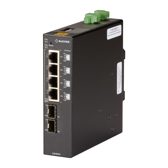
2.1 INTRODUCTION This user manual describes the functions of the 6-port Gigabit Industrial 802.3bt 60 W PoE Ethernet switch. The LIE402A is an industrial unmanaged Ethernet switch that features two SFP uplink ports and four 10/100/1000 RJ-45 Power-over-Ethernet (PoE) ports. -
Page 7: Reset Button
NEED HELP? LEAVE THE TECH TO US LIVE 24/7 CHAPTER 2: OVERVIEW TECHNICAL SUPPORT 1.877.877.2269 2.2.2 RESET BUTTON A Reset Button is available on the front of the module to clear all buffers and memory on the module. Press and hold the reset button for more than 5 seconds to clear the buffers and memory. -
Page 8: Installation
NEED HELP? LEAVE THE TECH TO US LIVE 24/7 CHAPTER 3: INSTALLATION TECHNICAL SUPPORT 1.877.877.2269 3. INSTALLATION Follow these steps: STEP 1: CONFIGURE DIP SWITCHES DIP switches are located on the top of the module. The DIP switches are used to configure modes of operation, networking features, and PoE reset. - Page 9 NEED HELP? LEAVE THE TECH TO US LIVE 24/7 CHAPTER 3: INSTALLATION TECHNICAL SUPPORT 1.877.877.2269 DIP Switch Definitions SW1 and SW2 - Mode of Operation The module supports Switch, Directed Switch, and Dual Device modes. The modes are described with MAC learning enabled. When MAC learning is disabled, unicast packets are forwarded to all ports. Function LEFT LEFT...
- Page 10 NEED HELP? LEAVE THE TECH TO US LIVE 24/7 CHAPTER 3: INSTALLATION TECHNICAL SUPPORT 1.877.877.2269 Dual Device Mode When configured for Dual Device Mode, the module is configured as two independent Layer 2 switches. Port F1 is associated with ports P1 and P2 and port F2 is associated with ports P3 and P4.
- Page 11 NEED HELP? LEAVE THE TECH TO US LIVE 24/7 CHAPTER 3: INSTALLATION TECHNICAL SUPPORT 1.877.877.2269 Uplink Redundancy When configured for Uplink Redundant Mode “no return to primary”, the uplink ports operate as redundant links. A fault on the primary port F1, will cause a fail over to the secondary port F2 within 50 msec. Port F1 will become the secondary port once the failure condition has been restored because “no return to primary”...
-
Page 12: Step 2: Installing The Module
20 Amps, and installed per the National Electrical Code, ANSI/NFPA-70. The LIE402A requires +50 to +57 VDC inclusive of tolerances (4.46 A @ 56 VDC maximum rated power). Be sure to provide appropriate overloading protection on the DC power source outlets used. - Page 13 NEED HELP? LEAVE THE TECH TO US LIVE 24/7 CHAPTER 3: INSTALLATION TECHNICAL SUPPORT 1.877.877.2269 Strip approximately 3/8 of an inch of insulation from the power cable wires. The ground wire may need additional insulation removed to secure it to the grounding screws. Connect the ground wire to the grounding screws on the back of the module.
-
Page 14: Step 4: Connect Cables
NEED HELP? LEAVE THE TECH TO US LIVE 24/7 CHAPTER 3: INSTALLATION TECHNICAL SUPPORT 1.877.877.2269 During the installation, ensure that the ground potentials are maintained throughout the system connections. This includes but is not limited to the power source ground and any shielded cabling grounds. WARNING!!! NEVER ATTEMPT TO OPEN THE CHASSIS OR SERVICE THE POWER SUPPLY. - Page 15 NEED HELP? LEAVE THE TECH TO US LIVE 24/7 CHAPTER 3: INSTALLATION TECHNICAL SUPPORT 1.877.877.2269 Power LED Indicators Uplink Ports LED Indicators Legend Indicator Description No link Green - ON Port linked at 10 Mbps (100+1000) Green - Blinking at 10Hz Port data activity at 10 Mbps Green - Blinking at 1Hz Port linked at 10 Mbps and in redundant secondary mode...
- Page 16 NEED HELP? LEAVE THE TECH TO US LIVE 24/7 CHAPTER 3: INSTALLATION TECHNICAL SUPPORT 1.877.877.2269 RJ-45 LED Indicators NOTE: The PSE LED may turn Amber (ON) when a non-PD device is connected to the port. NOTE: When disconnecting and reconnecting the cable from the RJ-45 PSE ports, it is required to wait at least 5 seconds before reconnecting the cable to the RJ-45 PSE port.
-
Page 17: Fcc Statement
NEED HELP? LEAVE THE TECH TO US LIVE 24/7 APPENDIX A: REGULATORY INFORMATION TECHNICAL SUPPORT 1.877.877.2269 A.1 FCC STATEMENT This equipment generates, uses, and can radiate radio-frequency energy, and if not installed and used properly, that is, in strict accordance with the manufacturer’s instructions, may cause interference to radio communication. It has been tested and found to comply with the limits for a Class A computing device in accordance with the specifications in Subpart B of Part 15 of FCC rules, which are designed to provide reasonable protection against such interference when the equipment is operated in a commercial environment. -
Page 18: Nom Statement
NEED HELP? LEAVE THE TECH TO US LIVE 24/7 APPENDIX A: REGULATORY INFORMATION TECHNICAL SUPPORT 1.877.877.2269 A.2 NOM STATEMENT 1. Todas las instrucciones de seguridad y operación deberán ser leídas antes de que el aparato eléctrico sea operado. 2. Las instrucciones de seguridad y operación deberán ser guardadas para referencia futura. 3. -
Page 19: Disclaimer
B.1 DISCLAIMER Black Box Corporation shall not be liable for damages of any kind, including, but not limited to, punitive, consequential or cost of cover damages, resulting from any errors in the product information or specifications set forth in this document and Black Box Corporation may revise this document at any time without notice. - Page 20 NEED HELP? LEAVE THE TECH TO US LIVE 24/7 TECHNICAL SUPPORT 1.877.877.2269 © COPYRIGHT 2021. BLACK BOX CORPORATION. ALL RIGHTS RESERVED. LIE402A_USER_REV1.PDF...
Need help?
Do you have a question about the LIE402A and is the answer not in the manual?
Questions and answers