Sign In
Upload
Download
Table of Contents
Contents
Add to my manuals
Delete from my manuals
Share
URL of this page:
HTML Link:
Bookmark this page
Add
Manual will be automatically added to "My Manuals"
Print this page
×
Bookmark added
×
Added to my manuals
Manuals
Brands
Black Box Manuals
Switch
LIG1014A
User manual
Black Box LIG1014A User Manual
Industrial ethernet switches
Hide thumbs
Also See for LIG1014A
:
User manual
(84 pages)
,
Quick start manual
(24 pages)
1
Table Of Contents
2
3
4
5
6
7
8
9
10
11
12
13
14
15
16
17
18
19
20
21
22
23
24
25
26
27
28
29
30
31
32
33
34
35
36
37
38
39
40
41
42
43
44
45
46
47
48
49
50
51
52
53
54
55
56
57
58
59
60
61
62
63
64
65
66
67
68
69
70
71
72
73
74
75
76
77
78
79
80
81
82
83
84
85
86
87
88
89
90
91
92
93
94
95
96
page
of
96
Go
/
96
Contents
Table of Contents
Bookmarks
Table of Contents
Table of Contents
Safety Instructions
1 Specifications
Lig1014A
Lig1080A
Lig1082A
Lie1014A
Lie1080A
Lie1082A
System Statistics
2 Overview
Introduction
Available Models
Features
What's Included
Hardware Description
Lig1014A
Lig1080A
Lig1082A
Lie1014A
Lie1080A
Lie1082A
3 Installation
DIN Rail Mounting
Wallmounting
Alarm Relay and Ground
Connecting the Ethernet Interface (RJ-45 Ethernet)
Connecting the Ethernet Interface (Fiber, SFP)
Power Connection
Alarm Relay and Ground
System Reset
Console Connection
Web Interface Initialization (Optional)
CLI Initialization and Configuration (Optional)
Upgrade/Downgrade Software
Reset to Default and Save Configuration
LED Status Indicators
4 Vlan Application
Example 1: Default VLAN Settings
Example 2: Port-Based Vlans
Example 3: IEEE 802.1Q Tagging
5 Security Application
Case 1: ACL for MAC Address
Case 2: ACL for IP Address
Case 3: ACL for L4 Port
Case 4: ACL for Tos
6 Ring Version 2 Application
Ring Version2 Feature
How to Configure Ringv2
7 Qos Application
Sp/Spwrr
Example 1: SPQ Without Shaping (Default Profile)
Example 2: SFQ with Shaping
8 Igmp Application
Example 1
Example 2
Example 3
How to Configure VLC
Authentication Application
802.1X Timer
Radius Server Configuration
Example
10 Power over Ethernet Application (for Lie1014A, Lie1080A and Lie1082A Models Only)
Reserved Power Determination
Power Management Mode
Other Settings
Poe Power Scheduling and Reset
Example 1
Example 2
Appendix A. Regulatory Information
FCC Statement
NOM Statement
Appendix B. Trademarks/Disclaimer
Trademarks Used in this Manual
Disclaimer
Advertisement
Quick Links
1
Lig1014A
2
Lig1082A
3
Lie1082A
4
Connecting the Ethernet Interface (Rj-45 Ethernet)
5
System Reset
6
Console Connection
7
Web Interface Initialization (Optional)
8
Reset to Default and Save Configuration
Download this manual
USER MANUAL
LIG1014A, LIG1080A, LIG1082A, LIE1014A, LIE1080A, LIE1082A
INDUSTRIAL
ETHERNET
SWITCHES
24/7 TECHNICAL SUPPORT AT 1.877.877.2269 OR VISIT BLACKBOX.COM
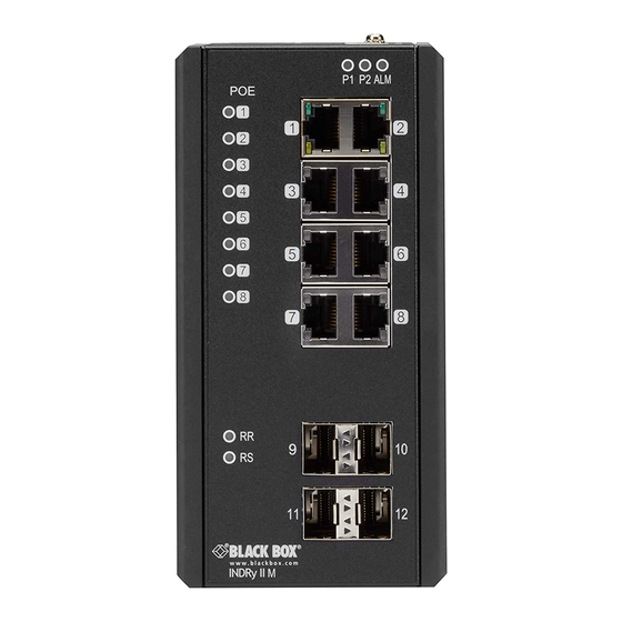
P1 P2 ALM
1
2
3
4
5
6
7
8
P1 P2 ALM
POE
1
1
2
2
3
3
4
4
5
6
8
7
9
10
RR
11
12
RS
13
14
P1
P2 ALM
1
2
3
4
5
6
7
8
Table of
Contents
Previous
Page
Next
Page
1
2
3
4
5
Advertisement
Table of Contents
Need help?
Do you have a question about the LIG1014A and is the answer not in the manual?
Ask a question
Questions and answers
Related Manuals for Black Box LIG1014A
Switch Black Box LIG1014A User Manual
Industrial managed gigabit ethernet switch (84 pages)
Switch Black Box LIG1014A Quick Start Manual
Industrial managed gigabit ethernet switch (24 pages)
Switch Black Box LIE1014A Quick Start Manual
Industrial (13 pages)
Switch Black Box LIG1082A User Manual
Industrial ethernet switches (96 pages)
Switch Black Box LIE402A User Manual
802.3bt 60 w poe gigabit industrial unmanaged switch (20 pages)
Switch Black Box LH8112A Installation And User Manual
10/100 managed hub (132 pages)
Switch Black Box LBH100A-SC User Manual
Black box lbh100a-sc: user guide (75 pages)
Switch Black Box Stackable MiniHub Manual
(27 pages)
Switch Black Box LGB6026A Management Manual
Gigabit l3 managed switch with 10g uplinks, 24-port or 48-port (1289 pages)
Switch Black Box LGB416A User Manual
16-/24-port 10/100/1000 rj-45 unmanaged gigabit switches (12 pages)
Switch Black Box • LGH1000 Series User Manual
Lgh1000 series hardened ethernet switch, (4) 10/100/1000 mbps, (1) ge sfp (20 pages)
Switch Black Box LPH240A-H Operation Manual
6-port 10/100 poe edge switch (56 pages)
Switch Black Box LGB5124A Quick Start Manual
Sfp managed switch eco provides (20) gigabit ethernet sfp and (4) gigabit ethernet combo rj-45/sfp connections (24 pages)
Switch Black Box LGB408A Manual For Use
8-port gigabit unmanaged switch (20 pages)
Switch Black Box LGT616A-JP User Manual
16-port gigabit web smart switch (28 pages)
Switch Black Box LGB105A Manual Information
5- and 8-port gigabit ethernet switches (8 pages)
This manual is also suitable for:
Lig1080a
Lig1082a
Lie1014a
Lie1080a
Lie1082a
Table of Contents
Print
Rename the bookmark
Delete bookmark?
Delete from my manuals?
Login
Sign In
OR
Sign in with Facebook
Sign in with Google
Upload manual
Upload from disk
Upload from URL


Need help?
Do you have a question about the LIG1014A and is the answer not in the manual?
Questions and answers