Table of Contents
Advertisement
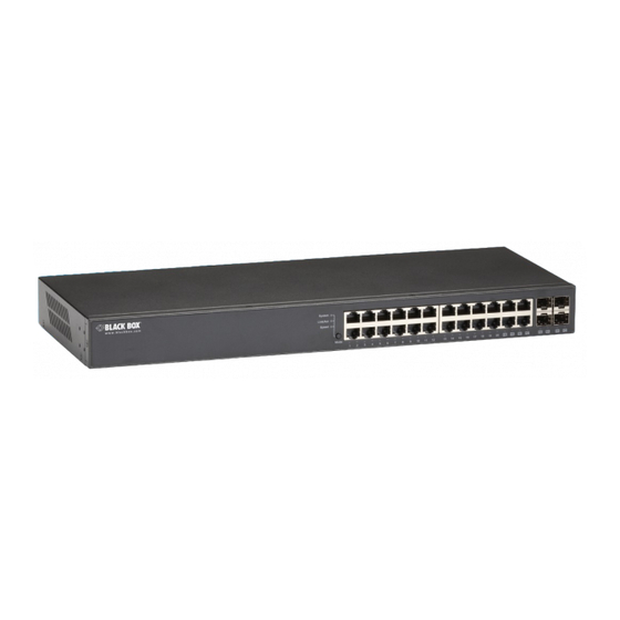
Gigabit Smart Switch Eco Fanless
Supports http and SNMP interface for switch
management.
• The LGB2118A has (16) 10-/100-/1000-Mbps TP ports
and (2) Gigabit SFP ports.
• The LGB2124A has (20) 10-/100-/1000-Mbps TP ports
and (4) Gigabit TP/SFP dual-media ports.
Order toll-free in the U.S.: Call 877-877-BBOX (outside U.S. call 724-746-5500)
Customer
FREE technical support 24 hours a day, 7 days a week: Call 724-746-5500 or fax 724-746-0746
Support
Mailing address: Black Box Corporation, 1000 Park Drive, Lawrence, PA 15055-1018
Information
Web site: www.blackbox.com • E-mail: info@blackbox.com
BLACK BOX
LGB2118A
LGB2124A
®
Advertisement
Table of Contents

Subscribe to Our Youtube Channel
Related Manuals for Black Box LGB2118A


Summary of Contents for Black Box LGB2118A
-
Page 1: Black Box
Order toll-free in the U.S.: Call 877-877-BBOX (outside U.S. call 724-746-5500) Customer FREE technical support 24 hours a day, 7 days a week: Call 724-746-5500 or fax 724-746-0746 Support Mailing address: Black Box Corporation, 1000 Park Drive, Lawrence, PA 15055-1018 Information Web site: www.blackbox.com • E-mail: info@blackbox.com... - Page 2 Trademarks Used in this Manual Trademarks Used in this Manual Black Box and the Double Diamond logo are registered trademarks of BB Technologies, Inc. Intel is a registered trademark of Intel Corporation. Microsoft and Internet Explorer are registered trademarks of Microsoft Corporation.
- Page 3 FCC and IC RFI Statements Federal Communications Commission and Industry Canada Radio Frequency Interference Statements This equipment generates, uses, and can radiate radio-frequency energy, and if not installed and used properly, that is, in strict accordance with the manufacturer’s instructions, may cause inter ference to radio communication. It has been tested and found to comply with the limits for a Class A computing device in accordance with the specifications in Subpart B of Part 15 of FCC rules, which are designed to provide reasonable protection against such interference when the equipment is operated in a commercial environment.
-
Page 4: Instrucciones De Seguridad
NOM Statement Instrucciones de Seguridad (Normas Oficiales Mexicanas Electrical Safety Statement) 1. Todas las instrucciones de seguridad y operación deberán ser leídas antes de que el aparato eléctrico sea operado. 2. Las instrucciones de seguridad y operación deberán ser guardadas para referencia futura. 3. -
Page 5: Table Of Contents
2.2 Features ..................................9 2.3 What’s Included ................................10 2.4 Hardware Description ..............................11 2.4.1 18-Port Gigabit Smart Switch Eco Fanless (LGB2118A) ..................11 2.4.2 24-Port Gigabit Smart Switch Eco Fanless (LGB2124A) ..................12 3. Installation ................................... 15 3.1 Starting Up the Switch ..............................15 3.1.1 Hardware and Cable Installation ......................... - Page 6 5.4.3 Software Upgrade ..............................70 5.4.4 Configuration File Transfer ..........................70 5.4.5 Logout................................71 6. Troubleshooting ...................................72 6.1 Resolving Line Condition .............................72 6.2 Questions and Answers ...............................72 6.3 Contacting Black Box..............................72 6.4 Shipping and Packaging ..............................72 Appendix. MIB ..................................73 724-746-5500 | blackbox.com Page 6...
-
Page 7: Specifications
1000 FX LGB2124A: **SFP 21–24 NOTE: *Ports 9 and 10 on the LGB2118A SFP fiber ports and **Ports 21–24 on the LGB2124A are TP/SFP fiber dual media ports with auto detection function. Optional SFP modules support LC transceivers. Priority Queueing — 802.1p Class of Service with 2-level priority queueing Programmable Maximum Ethernet Frame Length —... -
Page 8: Management Software Specifications
Indicators — LGB2118A: (33) LEDs: (1) System Power, (16) LINK/ACT and (16) SPD LEDs for 10/100/1000 M TP Ports 1 to 16, (2) LINK/ACT and (2) SPD LEDs for 1000 M SFP fiber Ports 19 to 20;... -
Page 9: Overview
• VLAN: Supports Port-based VLAN, IEEE 802.1Q Tag VLAN. LGB2118A supports 18 active VLANs and LGB2124A supports 24 active VLANs and VLAN IDs 1–4094. • Port Trunking (LGB2118A Only): Allows one or more links to be aggregated together to form a link aggregation group by the static setting. -
Page 10: What's Included
• Uses full-duplex flow control (IEEE 802.3x) and half-duplex backpressure. • Features extensive front-panel diagnostic LEDs: For LGB2118A: System: Power, TP Port 1–16: LINK/ACT, 10-/100-/1000-Mbps, SFP Port 17 and 18: SFP (LINK/ACT); For LGB2124A: System: Power, TP Port 1–24: LINK/ACT, 10-/100-/1000-Mbps, SFP Port 21, 22, 23, and 24: SFP (LINK/ACT) •... -
Page 11: Hardware Description
Chapter 2: Overview 2.4 Hardware Description 2.4.1 18-Port Gigabit Smart Switch Eco Fanless (LGB2118A) Figures 2-1 ad 2-2 show the front and back panels of the switch. Table 2-2 describes its components. Table 2-3 describes the LEDs in detail. 7 1 2 3 Figure 2-1. -
Page 12: 24-Port Gigabit Smart Switch Eco Fanless (Lgb2124A)
Chapter 2: Overview Table 2-3. LGB2118A LED functions. Color Function (1) System Power LED Green Lit when power is on. Steady green Lit when connection with remote device is good. (16) LINK/ACT LEDs Blinking green Blinks when any traffic is present. - Page 13 Chapter 2: Overview Table 2-4. LGB2124A components. Number Component Description (1) Mode button Switches between what is being displayed by LEDs. (24) TP port status LEDs For details, see Table 2-5. (24) TP port speed LEDs For details, see Table 2-5. (4) SFP port status LEDs For details, see Table 2-5.
- Page 14 Optional Modules for LGB2118A and LGB2124A On the LGB2118A switch, Ports 17–18 are SFP fiber module ports. On the LGB2124A, Ports 21–24 include two types of media— TP and SFP Fiber (with LC connectors); they support 10-/100-/1000-Mbps TP or 1000-Mbps SFP Fiber with auto-detect function.
-
Page 15: Installation
Chapter 3: Installation 3. Installation 3.1 Starting Up the Switch This section will give users a quick start for: • Hardware and cable installation. • Management station installation. • Software booting and configuration. 3.1.1 Hardware and Cable Installation CAUTION: Wear a grounding device to avoid damage from electrostatic discharge. Make sure that power switch is OFF before you insert the power cord into the power source. -
Page 16: Cabling Requirements
They are SX, LX, LHX, XD, and ZX. The following table lists the types of fiber that the switch supports. If you don’t see the cable type you need, contact Black Box Technical Support at 724-746-5500 or info@blackbox.com. - Page 17 802.3 series specification of Media Access Control (MAC) and PHY, and the timer from some OSI layer 2 protocols such as 802.1d, 802.1q, LACP (for LGB2118A only), and so on. The fiber, TP cables, and devices’ bit-time delay (round trip) are as follows: Table 3-2.
- Page 18 Chapter 3: Installation Typical Network Topology in Deployment A hierarchical network with minimum levels of switches may reduce the timing delay between the server and the client station. This approach will minimize the number of switches in any one path, lower the possibility of network loops, and improve network efficiency.
- Page 19 Chapter 3: Installation 3. The switch manager has to assign different names for each VLAN group at one switch. Case 2b: Port-based VLAN (See Figure 3-4). VLAN 1 VLAN 2 VLAN 3 VLAN 4 Figure 3-4. Port-based VLAN diagram. 1. VLAN1 members cannot access VLAN2, VLAN3, and VLAN4 members. 2.
-
Page 20: Configuring The Management Agent Of The Gigabit Smart Switch Eco Fanless
Chapter 3: Installation 3.1.3 Configuring the Management Agent of the Gigabit Smart Switch Eco Fanless Via the Web, the switch can set up the management function. Use any one of them to monitor and configure the switch. Configuring the Management Agent of the Gigabit Smart Switch Eco Fanless through the Ethernet Port There are two ways to configure and monitor the switch through the switch’s Ethernet port. -
Page 21: Address Assignment
Chapter 3: Installation Figure 3-7. The Login screen for the Web. 3.1.4 Address Assignment For IP address configuration, there are four parameters that need to be filled in. They are IP address, Subnet Mask, Default Gateway, and DNS. IP address: The address of the network device in the network is used for internetworking communication. - Page 22 Chapter 3: Installation Class B: A Class B IP address ranges between 128.0.0.0 and 191.255.255.255. Each class B network has a 16-bit network prefix followed by a 16-bit host address. There are 16,384 (2 )/16 networks able to be defined with a maximum of 65534 (2 –2) hosts per network.
- Page 23 Chapter 3: Installation Figure 3-12. Subnet mask. In this diagram, the subnet mask is 25 bits long, 255.255.255.128, and contains 126 members in the subnetted network. The length of the network prefix equals the number of the bit with 1s in that subnet mask. This enables the switch to count the number of IP addresses matched.
-
Page 24: Typical Applications
3.2 Typical Applications The LGB2118A implements (16) Gigabit Ethernet TP ports with auto MDI-X and (2) slots for the removable module supporting LC fiber SFP modules. The LGB2124A has (20) Gigabit Ethernet TP ports with auto MDI-X and (4) slots for the removable combo module supporting twisted-pair and LC fiber SFP modules. - Page 25 Chapter 3: Installation Gigabit Smart Switch Eco Fanless (LGB2124A) Rack-based media Copper cables Gigabit Smart Switch converter system RJ-45 Eco Fanless (LGB2124A) Fiber cable Copper cables RJ-45 Gigabit Smart Switch Eco Fanless Fiber cables (LGB2124A) Copper cables RJ-45 Copper cable RJ-45 Media Converter...
- Page 26 Chapter 3: Installation Fig. 3-14 is a system-wide basic reference connection diagram. This diagram demonstrates how the switch connects with other network devices and hosts. Gigabit Smart Switch Eco Fanless (LGB2124A) Copper cables Copper cables RJ-45 RJ-45 Financial Figure 3-15. Peer-to-peer network connection. Sales R &...
-
Page 27: Basic Concepts And Management
Chapter 4: Basic Concepts and Management 4. Basic Concepts and Management This chapter describes the features used to manage this switch and how they work. 4.1 Ethernet Ethernet originated and was implemented at Xerox in Palo Alto, CA in 1973 and was successfully commercialized by Digital ®... -
Page 28: Logical Link Control (Llc)
Chapter 4: Basic Concepts and Management Figure 4-2. MAC sub layer in physical layer in OSI model. This diagram shows the Ethernet architecture, LLC sub-layer and MAC sub-layer, which operate at the Data Link layer, and transceivers, which work at the Physical layer in the OSI model. In this section, we describe the MAC sub-layer. 4.2 Logical Link Control (LLC) The data link layer consists of both the sub-layers of MAC and MAC-client. -
Page 29: Media Access Control (Mac)
Chapter 4: Basic Concepts and Management Table 4-2. SSAP address field options. OxAAAA SNAP 0xE0E0 Novell ® 0x F0F0 NetBios 0xFEFE IOS network layer PDU 0xFFFF Novell IPX 802.3 RAW packet 0x4242 STP BPDU 0x0606 0x9898 LLC type 1 is a connectionless service, LLC type 2 is a connection-oriented service, and LLC type 3 acknowledges a connectionless service and has three types of LLC frames for all classes of service. -
Page 30: Ethernet Frame Format
Chapter 4: Basic Concepts and Management The first three bytes are Organizational Unique Identifier (OUI) codes assigned by IEEE. The last three bytes are the serial number assigned by the vendor of the network device. All six bytes are stored in non-volatile memory in the device. Their format is shown in Table 4-3. - Page 31 Chapter 4: Basic Concepts and Management • Length/Type — This field indicates either the number of the data bytes contained in the data field of the frame, or the Ethernet type of data. If the value of first two bytes is less than or equal to 1500 in decimal notation, the number of bytes in the data field is equal to the Length/Type value, that is, this field acts as a Length indicator at this moment.
- Page 32 Chapter 4: Basic Concepts and Management 4. During the transmission, the MAC keeps monitoring the status of the medium. If no collision happens until the end of the frame, it transmits successfully. If there is a collision, the MAC will send the patterned jamming bit to guarantee the collision event is propagated to all involved network devices, then wait for a random period of time, called back off time.
-
Page 33: Flow Control
Chapter 4: Basic Concepts and Management Table 4-5. Ethernet parameters for half-duplex mode. Parameter Value/LAN 10BASE 100BASE 1000BASE 328 feet (100 m) for UTP 328 feet (100 m) for UTP Max. collision domain DTE to DTE 328 feet (100 m) 1351.7 feet (412 m) for fiber 1043.3 feet (316 m) for fiber Max. - Page 34 Chapter 4: Basic Concepts and Management Inter-frame Gap time After the end of a transmission, if a network node is ready to transmit data out and if there is no carrier signal on the medium at that time, the device will wait for a period of time known as an inter-frame gap time to clear and stabilize the medium, as well as to have the jobs ready, such as adjusting buffer counter, updating counter, and so on, in the receiver site.
- Page 35 Chapter 4: Basic Concepts and Management What if VLAN tagging is applied? VLAN tagging is a 4-byte long data immediately following the MAC source address. When tagged VLAN is applied, the Ethernet frame structure will change slightly. Collision domain 2 Collision domain 1 Collision Collision...
- Page 36 Chapter 4: Basic Concepts and Management When MAC parses the received frame and finds a reserved special value 0x8100 at the location of the Length/Type field of the normal non-VLAN frame, it will interpret the received frame as a tagged VLAN frame. If this happens in a switch, the MAC will forward it, according to its priority and egress rule, to all the ports associated with that VID.
-
Page 37: How Does A Switch Work
4.5 How Does a Switch Work? The LGB2118A switch is a layer 2 Ethernet Switch equipped with (16) TP Gigabit Ethernet ports and (2) slots for optional SFP fiber modules. The LGB2124A switch has (20) TP ports and (4) slots for optional TP/SFP combo modules. Each port on the switch is an independent LAN segment and thus has 26 LAN segments and 26 collision domains, in contrast to the traditional shared Ethernet hub, in which all ports share the same media and use the same collision domain and thus limit the bandwidth use. -
Page 38: Virtual Lan
Chapter 4: Basic Concepts and Management How does a switch operate? A Layer 2 switch uses some features of the Data Link layer in the OSI model to forward the packet to the destination port(s). Here we introduce some important features of switches and how they work. •... - Page 39 Chapter 4: Basic Concepts and Management Mini Mini frame computer Ethernet switch BACKBONE Ethernet switch Ethernet switch Ethernet switch Printer Printer Workstations Figure 4-8. In the figure above, all stations are within the same broadcast domain. For these stations, the traffic is getting congested when adding more stations to the broadcast domain.
- Page 40 Chapter 4: Basic Concepts and Management Router Ethernet switch Ethernet switch Ethernet switch BACKBONE Ethernet switch Figure 4-9. Virtual LAN. By applying VLAN technology, you can configure the system shown in Figure 4-9. You can partition the users into the different logical networks that have their own broadcast domain.
- Page 41 Chapter 4: Basic Concepts and Management Figure 4-10. Tag format. VLAN Protocol ID: 8100 is reserved for VLAN-tagged frame. User Priority: 3 bits long. User priority is defined from 7–0. 0 is the lowest priority. CFI: Canonical Format Indicator is 1 bit long. It encapsulates a token ring packet so it can travel across the Ethernet. Usually, it is set to 0.
- Page 42 Chapter 4: Basic Concepts and Management 2. If the VID is not a null VID (VID is not equal to 0), then use the value to classify the VLAN group. Egress Rule: An egress list is used to make the tagging and forwarding decision on an outgoing port. It specifies the VLANs whose packets can be transmitted out and specifies if the packet should be tagged or not.
-
Page 43: Link Aggregation (Lgb2118A Only)
10.1.1.0/24 Here we apply the subnet mask 255.255.255, and each VLAN can support 254 nodes. 4.7 Link Aggregation (LGB2118A Only) Link Aggregation combines the bandwidth of more than one port to an assigned logical link. This increases total bandwidth to the targeted device. - Page 44 Chapter 4: Basic Concepts and Management There are also some constraints when applying LACP: 1. LACP does not support inter-switch bandwidth aggregation. 2. The ports aggregated must operate in full-duplex mode. 3. The ports in the same Link Aggregation Group must operate at the same speed, for example, all 100 Mbps or all 1000 Mbps. You cannot aggregate a 1000 Mbps port and two 100 Mbps ports for a 1.2 Gbps trunk port.
-
Page 45: Operation Of Web-Based Management
This chapter explains how to manage your Gigabit Smart Switch Eco Fanless and how to configure the 10-/100-/1000-Mbps TP Ports and Gigabit SFP Fiber ports on the switch via Web user interfaces. The LGB2118A provides (16) fixed Gigabit Ethernet TP ports and (2) optional SFP ports. - Page 46 Chapter 5: Operation of Web-based Management Page Layout Information The top part of the information page, shows the front panel of the switch. Linked ports will be displayed in green, and linked-off ports will be in black. For the optional modules, the slots with no module will only show covered plates, the other slots with installed modules would show modules.
-
Page 47: Configuration
Chapter 5: Operation of Web-based Management 5.2 Configuration Configuration includes the following functions: System Configuration, Ports Configuration, VLAN Mode Configuration, VLAN Group Configuration, VLAN Isolation, Aggregation, IGMP Snooping, Mirroring, Loop Detection, Broadcast Storm Protection, and QoS. Figure 5-3. Configuration menu function tree. 5.2.1 System Information System configuration is one of the most important functions. - Page 48 Chapter 5: Operation of Web-based Management Figure 5-4. System Configuration menu. Function name: System Configuration Function description: Show system description, firmware version, hardware version, MAC address, serial number, active IP address, active subnet mask, active gateway, DHCP server, and lease time left. Set device name, DHCP enabled, fallback IP address, fallback subnet mask, fallback gateway, management VLAN, password, and inactivity timeout.
-
Page 49: Port Configuration
Chapter 5: Operation of Web-based Management DHCP Server: Shows the IP address of the DHCP server. The default is 0.0.0.0. Lease Time Left: Shows the lease time left for the DHCP client. Device Name: Set a special name for this switch. Up to 16 characters are allowed in this parameter. Any alphanumeric characters and the null character are acceptable. - Page 50 Chapter 5: Operation of Web-based Management Figure 5-6. Port Configuration menu. Parameter description: Enable Jumbo Frames: This function supports jumbo frames of up to 9600 bytes. Just tick the check box to enable it. The default is disable. Power Saving Mode: This function supports power saving. Select Full/ Link-up/Link-down/Disable using the drop-down menu. Default: disable Link: Show link status of this port.
-
Page 51: Vlan Mode Configuration
Chapter 5: Operation of Web-based Management Table 5-2. Media supported. Media Type Auto-negotiation Speed Duplex 1000M TP ON/OFF 10/100/1000M Full for all, Half for 10/100 1000M Fiber ON/OFF 1000M Full In Auto Speed mode, there is no default value. In Forced mode, the default value depends on your setting. Flow Control: You can tick the check box to enable flow control. - Page 52 Chapter 5: Operation of Web-based Management Figure 5-8. tag-VLAN Mode. Figure 5-9. Per port configuration. Parameter description: VID: VLAN identifier. Each tag-based VLAN group has a unique VID. It appears only in tag-based mode. Member: In the modify function, this is used to enable or disable if a port is a member of the new added VLAN. “Enable” means it is a member of the VLAN.
- Page 53 Chapter 5: Operation of Web-based Management Packet Type: All: Forward all tagged and untagged packets. Tagged Only: Forward tagged packets only and discard untagged packets. PVID: This PVID range will be 1–4094. Before you set a number x as PVID, you have to create a Tag-based VLAN with VID x. For example, if port x receives an untagged packet, the switch will apply the PVID (assume as VID y) of port x to tag this packet, the packet then will be forwarded as the tagged packet with VID.
-
Page 54: Vlan Port Isolation Configuration
Chapter 5: Operation of Web-based Management Figure 5-11. Add or Remove VLAN Member. Parameter description: ID (Group ID): When you want to edit a VLAN group, you must select the Group ID field. Then, you will enter the Tag Base VLAN Group Setting or Port Base VLAN Group Setting page, depending on which VLAN mode you select. -
Page 55: Aggregation (Lgb2118A Only)
When unchecked, port isolation is disabled on that port. By default, port isolation is disabled on all ports. 5.2.6 Aggregation (LGB2118A Only) The Aggregation (Port Trunking) Configuration is used to configure the settings of Link Aggregation. You can bundle ports by the same speed, MAC, and full duplex to be a single logical port, so the logical port can aggregate the bandwidth of these ports. -
Page 56: Igmp Snooping
Chapter 5: Operation of Web-based Management 5.2.7 IGMP Snooping Function name: IGMP Snooping Configuration Function description: IGMP Snooping lets administrators configure a switch to constrain multicast traffic by listening to Internet Group Management Protocol (IGMP). After finishing the settings, click on the “Apply” button to start up the function. Figure 5-14. -
Page 57: Snmp
Chapter 5: Operation of Web-based Management Figure 5-15. Mirror ports configuration. 5.2.9 SNMP Any Network Management System (NMS) running the Simple Network Management Protocol (SNMP) can manage the managed devices equipped with an SNMP agent, provided that the Management Information Base (MIB) is installed correctly on the managed devices. - Page 58 Chapter 5: Operation of Web-based Management Figure 5-16. SNMP Configuration. Parameters description: SNMP enable: The term SNMP enable here is used for the activation or deactivation of SNMP. The default is “Disable.” Get/Set/Trap Community: Community name is used as password for authenticating if the requesting network management unit belongs to the same community group.
-
Page 59: Loop Detection
Chapter 5: Operation of Web-based Management 5.2.10 Loop Detection Function name: Loop Detection Configuration Function description: The loop detection is used to detect the presence of traffic. When a packet’s looping detection frame is received by the switch and has a MAC address the same as its own from a port, loop detection occurs. The port will be locked when it receives the looping detection frames. -
Page 60: Broadcast Storm Protection
Chapter 5: Operation of Web-based Management State: Show the status on the port. Protocol Enabled: Controls whether Loop Detection is enabled on this switch port. When a port number is chosen and Loop detection is enabled, the port detects the loop and the port will be locked. If no Loop occurred, the port remains unlocked. - Page 61 Chapter 5: Operation of Web-based Management Figure 5-18. Rate Limit Configuration. Parameter description: Mode: Controls whether Broadcast Strom Protection is enabled (as a whole). Packet Per Second: When the broadcast packet traffic in a second is higher than the threshold configured, Broadcast Storm Protection is enabled.
-
Page 62: Quality Of Service (Qos) Configuration
Chapter 5: Operation of Web-based Management Unlock port: Tick the checkbox next to the locked port and it will be opened and changed to unlocked. If you don’t tick the port checkbox, it remains locked. 5.2.12 Quality of Service (QoS) Configuration The QoS function supports VLAN-tagged priority that can set eight priorities, and DSCP (Differentiated Services Code Point) on Layer 3 of the network framework. - Page 63 Chapter 5: Operation of Web-based Management Figure 5-20. 802.1p Setting. Function name: DSCP QoS Mode Function description: In the late 1990s, the IETF redefined the meaning of the 8-bit Service Type field to accommodate a set of differentiated services (DS). Under the differentiated services interpretation, the first six bits are a codepoint, which is sometimes abbreviated DSCP, and the last two bits are left unused.
-
Page 64: Monitoring
Chapter 5: Operation of Web-based Management Figure 5-21. DSCP Setting. 5.3 Monitoring There are four functions contained in the monitoring function. Figure 5-22. Monitoring menu tree. 5.3.1 Statistics Overview Function name: Statistics Overview for all ports Function description: The section describes the Port statistics information and provides an overview of general traffic statistics for all switch ports. -
Page 65: Detailed Statistics
Chapter 5: Operation of Web-based Management Figure 5-23. Statistics Overview for all ports. Parameter description: Tx/Rx Bytes: The number of received and transmitted bytes per port. Tx/Rx Frames: The number of received and transmitted frames per port. Tx/Rx Errors: The number of frames received in error and the number of incomplete transmissions per port. 5.3.2 Detailed Statistics Function name: Detailed Statistics Function description: Display the detailed counting number of each port’s traffic. - Page 66 Chapter 5: Operation of Web-based Management Rx High Priority Packets: Number of Rx packets classified as high priority. Rx Low Priority Packets: Number of Rx packets classified as low priority. Rx Broadcast: Show the counting number of the received broadcast packet. Rx Multicast: Show the counting number of the received multicast packet.
-
Page 67: Igmp Status
Chapter 5: Operation of Web-based Management 5.3.3 IGMP Status Function name: IGMP Status Function description: Display IGMP status. In Fig. 5-26, the window shows the VLAN ID for each multicast group. Figure 5-25. IGMP Status. Parameter description: VLAN ID: Show VLAN ID for each multicast group. Querier: Show the group membership queries status. -
Page 68: Ping Status
Chapter 5: Operation of Web-based Management 5.3.4 Ping Status Function name: Ping Status Function description: Set up a target IP address for ping function and display ping status. In Fig. 5-27, the window shows the ping information. Figure 5-26. Ping. Parameter description: Ping Parameters: Target IP address: Set up a Target IP address to ping. -
Page 69: Maintenance
Chapter 5: Operation of Web-based Management 5.4 Maintenance There are five functions contained in the maintenance function. Figure 5-27. Maintenance menu tree. 5.4.1 Warm Restart You can reboot the switch in three ways: power up, hardware reset, and software reset. Press the “Reset” button on the front panel of your switch to reset the device and to retrieve default settings. -
Page 70: Factory Default
Chapter 5: Operation of Web-based Management 5.4.2 Factory Default Function name: Factory Default Function description: Factory Default provides the function to retrieve default settings and replace the current configuration. Except for the IP address setting, all settings will be restored to the factory default values when the “Factory Default” function is performed. -
Page 71: Logout
Chapter 5: Operation of Web-based Management 5.4.5 Logout In addition to the auto logout function we just mentioned in the system configuration section, the switch also allows administrators to logout manually using the Logout function. Function name: Logout Function description: The switch allows you to logout from the system to prevent other users from accessing the system without permission. -
Page 72: Troubleshooting
If you determine that your Gigabit Smart Switch Eco Fanless is malfunctioning, do not attempt to alter or repair the unit. It contains no user-serviceable parts. Contact Black Box Technical Support at 724-746-5500 or info@blackbox.com. Before you do, make a record of the history of the problem. We will be able to provide more efficient and accurate assistance if you have a complete description, including: •... -
Page 73: Appendix. Mib
Appendix: MIB Specifications Appendix: MIB Specifications A brief description of the MIB II Enterprise MIB brief appears next. For technical support or the latest version of MIB download, contact Black Box Technical Support at 724-746-5500 or info@blackbox.com. PRIVATE-GESM-SW10-MIB DEFINITIONS ::= BEGIN IMPORTS... - Page 74 NOTES 724-746-5500 | blackbox.com Page 74...
- Page 75 NOTES 724-746-5500 | blackbox.com Page 75...
- Page 76 About Black Box Black Box provides an extensive range of networking and infrastructure products. You’ll find everything from cabinets and racks and power and surge protection products to media converters and Ethernet switches all supported by free, live 24/7 Tech support available in 60 seconds or less.
Need help?
Do you have a question about the LGB2118A and is the answer not in the manual?
Questions and answers