Table of Contents
Advertisement
Quick Links
Industrial Managed Gigabit Ethernet Switch
Quick Start Guide
• LIG1014A has (10) RJ-45 ports and (4) SFP slots.
• LIE1014A has (8) PoE+ RJ-45 ports and (4) SFP slots.
Customer
Order toll-free in the U.S.: Call 877-877-BBOX (outside U.S.
Support
call 724-746-5500) • FREE technical support 24 hours a day, 7 days
Information
a week: Call 724-746-5500 or fax 724-746-0746
www.blackbox.com • info@blackbox.com
LIG1014A
LIE1014A
Advertisement
Table of Contents

Subscribe to Our Youtube Channel
Related Manuals for Black Box LIG1014A


Summary of Contents for Black Box LIG1014A
- Page 1 LIE1014A Industrial Managed Gigabit Ethernet Switch Quick Start Guide • LIG1014A has (10) RJ-45 ports and (4) SFP slots. • LIE1014A has (8) PoE+ RJ-45 ports and (4) SFP slots. Customer Order toll-free in the U.S.: Call 877-877-BBOX (outside U.S.
-
Page 2: Table Of Contents
Trademarks Used in this Manual/Table of Contents Trademarks Used in this Manual Black Box and the Double Diamond logo are registered trademarks of BB Technologies, Inc. Any other trademarks mentioned in this manual are acknowledged to be the property of the trademark owners. - Page 3 FCC and IC RFI Statements FEDERAL COMMUNICATIONS COMMISSION AND INDUSTRY CANADA RADIO FREQUENCY INTERFERENCE STATEMENTS This equipment generates, uses, and can radiate radio-frequency energy, and if not installed and used properly, that is, in strict accordance with the manufacturer’s instructions, may cause inter ference to radio communication. It has been tested and found to comply with the limits for a Class A computing device in accordance with the specifications in Subpart B of Part 15 of FCC rules, which are designed to provide reasonable protection against such interference when the equipment...
- Page 4 NOM Statement 4. Todas las instrucciones de operación y uso deben ser seguidas. 5. El aparato eléctrico no deberá ser usado cerca del agua—por ejemplo, cerca de la tina de baño, lavabo, sótano mojado o cerca de una alberca, etc. 6.
- Page 5 NOM Statement 16. El cable de corriente deberá ser desconectado del cuando el equipo no sea usado por un largo periodo de tiempo. 17. Cuidado debe ser tomado de tal manera que objectos liquidos no sean derramados sobre la cubierta u orificios de ventilación. 18.
-
Page 6: Specifications
(4) 100/1000BASE-SFP module slot Ingress IP30 protection Dimensions (with- LIG1014A: 6.0"H x 2.4"W x 4.3"D out DIN rail clip) (15.4 x 6 x 10.9 cm); LIE1014A: 6.1"H x 3.0"W x 5.0"D (15.4 x 7.7 x 12.8 cm) Weight LIG1014A: 2.4 lb. (1.1 kg);... - Page 7 Chapter 1: Specifications Power (continued) Maximum Power LIG1014A: 17 Watts; LIE1014A: Without PoE: 14 Watts, With PoE: 265 Watts Environmental Operating -40 to +167° F (-40 to +75° C), Temperature cold startup at -40° C Storage -40 to +185° F (-40 to +85° C)
-
Page 8: Front-Panel Diagram (Lig1014A)
Chapter 1: Specifications 1.1 Front-Panel Diagram: LIG10141 P1 P2 ALM Figure 1-3. Front panel, LIG1014A. 1.2 Front Panel Connectors: LIG1014A Connector Description (10) RJ-45 10/100/1000 Mbps speed auto-negotiation, MDI-MDI-X auto- crossover (4) SFP slots 100/1000BASE-SFP module slot 724-746-5500 | blackbox.com... -
Page 9: Front-Panel Leds: Lig1014A
Chapter 1: Specifications 1.3 Front-Panel LEDs: LIG1014A LED Name Status Condition (1) P1 LED ON, Green P1 power line has power P1 power line is disconnected or does not have power (1) P2 LED ON, Green P2 power line has power... -
Page 10: Front-Panel Diagram: Lie1014A
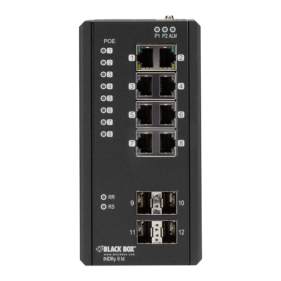
Chapter 1: Specifications 1.4 Front-Panel Diagram: LIE1014A P1 P2 ALM Figure 1-4. Front panel, LIE1014A. 1.7 Front Panel Connectors: LIE1014A Connector Description (8) RJ-45 PoE+ 10/100/1000 Mbps speed auto-negotiation, MDI-MDI-X auto- crossover with PoE+ (4) SFP slots 100/1000BASE-SFP module slot 724-746-5500 | blackbox.com Page 10... -
Page 11: Front-Panel Leds: Lie1014A
Chapter 1: Specifications 1.5 Front-Panel LEDs: LIE1014A LED Name Status Condition (8) PoE LEDs ON, Green PoE is working PoE is not working (1) P1 LED ON, Green P1 power line has power P1 power line is disconnected or does not have power (1) P2 LED ON, Green... -
Page 12: What's Included
Chapter 2: What's Included 2. What’s Included Your package should contain the following items. If anything is missing or damaged, contact Black Box Technical Support at 724-746-5500 or info@blackbox.com. • (1) Industrial Managed Gigabit Ethernet Switch - (10) RJ-45, (4) SFP (LIG1014A) -
Page 13: Installation
Chapter 3: Installation 3. Installation WARNING! When a connector is removed during installation, testing, or ser- vicing, or when an energized fiber is broken, your eyes might be exposed to to hazardous laser output power. 3.1 Mounting the Switch on a DIN Rail 1. -
Page 14: Mounting The Switch On A Wall
Chapter 3: Installation 3.2 Mounting the Switch on a Wall Screw the wall mount brackets on using the included M3 screws. M4 screw P1 P2 ALM Figure 3-2. Wallmounting. 3.3 Ethernet Interface The switch has two types of Ethernet interfaces: electrical (RJ-45) and optical (SFP) interfaces. - Page 15 Chapter 3: Installation The RJ- 45 pinout is shown in the following figure and tables. LED B LED A Pin 1 Pin 8 Figure 3-3. RJ-45 connector pinout. Table 3-1. RJ-45 pinout descriptions Assignment PoE Assignment (LIE1014A only) 1, 2 TX/RX+, TX/RX- Positive V port...
-
Page 16: Fiber, Sfp
Chapter 3: Installation 3.3.2 Fiber, SFP For both 100/1000 Mbps fiber speed connections, the SFP slots are available. The SFP slot accepts the fiber transceivers that typically have an LC connector. The fiber transceivers have options of multimode, single mode, long-haul or special- application transceivers. - Page 17 Chapter 3: Installation Table 3-2. Compatible SFP modules. Part Number Description SFP/1250 Extended Diagnostics, LC multimode, 850 LFP411 nm, 550 m SFP/1250 Extended Diagnostics, LC multimode, 1310 LFP412 nm, 2 km SFP/1250 Extended Diagnostics, LC LFP413 single-mode, 1310 nm, 10 km SFP/1250 Extended Diagnostics, LC LFP414 single-mode, 1310 nm, 40 km...
-
Page 18: Connecting The Power Terminal Block
Insert the positive and negative wires into V+ and V- contacts on the terminal block respectively and tighten the wire-clamp screws to prevent the wires from loosening. LIG1014A First power supply Second power supply PWR1 ALM PWR2 Reset Console Figure 3-4. Terminal block, LIG1014A. 724-746-5500 | blackbox.com Page 18... - Page 19 Chapter 3: Installation LIE1014A First power supply Second power supply PWR1 PWR2 Reset Console Figure 3-5. Terminal block, LIE1014A. 724-746-5500 | blackbox.com Page 19...
-
Page 20: Alarm Relay And Ground
Ethernet link failures. The relay output with current carrying capacity of 0.5 A @ 24 VDC. Extra power system Alarm system PWR1 ALM PWR2 Ground connector Reset Console Figure 3-6. Alarm relay, LIG1014A or LIE1014A. 724-746-5500 | blackbox.com Page 20... -
Page 21: Console Connection
PWR2 Reset Console Figure 3-7. Console connector, LIG1014A or LIE1014A. An RJ-45 (male) connector-to-RS-232 DB9 (female) connector cable is required. The RJ-45 connector of the cable is connected to the console connector on the switch. The pin assignment of the console cable is shown on the next page. -
Page 22: Connect And Login To Managed Switch
Chapter 3: Installation 3.7 Connect and Login to Managed Switch 1. Connecting to the Ethernet port (RJ45 Ethernet port) of Managed Switch. 2. Factory default IP: 192.0.2.1 3. Login with default account and password. Username: admin Password: (none) 3.8 CLI Initialization and Configuration (Optional) 1. - Page 23 Chapter 3: Installation 4. Change the IP with commands listed below: CLI Command: enable configure terminal interface vlan 1 ip address xxx.xxx.xxx.xxx.xxx.xxx.xxx.xxx exit 724-746-5500 | blackbox.com Page 23...
- Page 24 724-746-5500 or blackbox.com. About Black Box Black Box provides an extensive range of networking and infrastructure products. You’ll find everything from cabinets and racks and power and surge protection products to media converters and Ethernet switches all supported by free, live 24/7 Tech support available in 60 seconds or less.
Need help?
Do you have a question about the LIG1014A and is the answer not in the manual?
Questions and answers