Sign In
Upload
Manuals
Brands
SystemAir Manuals
Air Handlers
Geniox 10
SystemAir Geniox 10 Manuals
Manuals and User Guides for SystemAir Geniox 10. We have
2
SystemAir Geniox 10 manuals available for free PDF download: User Manual
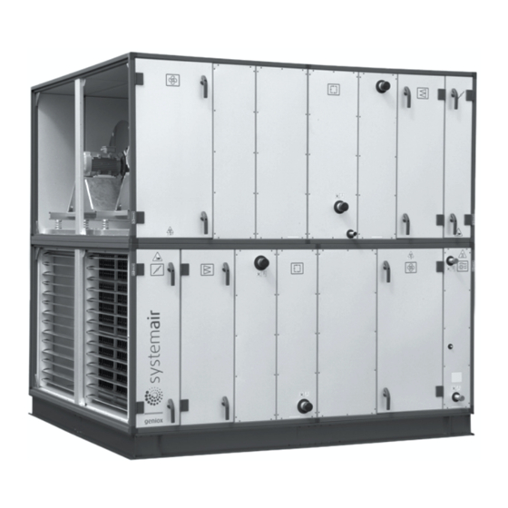
SystemAir Geniox 10 User Manual (112 pages)
Brand:
SystemAir
| Category:
Air Handlers
| Size: 3.23 MB
Table of Contents
Table of Contents
4
A Manufacturer
9
B Name of Machines
9
C Declaration of Conformity - Example
10
D General Descriptions, Dangers and Warnings
11
Overview Via Pictograms on the Inspection Side of the Unit
11
Where Are Pictograms Placed on the Units
11
Weight of each Section and Production Number - Example for the Geniox Unit
12
CE Label - Example for the Geniox Unit
12
Pictograms for All Available Functions in the Units
13
Pictograms about Warnings and Dangers on the Units
14
Data about the Unit According to Cards and Labels in and on the Unit
14
Machine Card with Unique Data on Every Unit
14
Label with Data about the Cabinet - Example
15
Flowchart - Example of the Label Placed on or with the Cabinet
15
Symbols in the Flowchart and Explanation about the Symbols
16
Example of Label Placed on or with the Cabinet - Terminal Plan for External Components
17
Hand Terminal
17
Dimensions of the Units
17
Ordinary Automatically Operation - Only Manual Operation by New Parameters
18
Warnings about Dangers
18
E Drawings, Diagrams, Guides and Instructions for the Use, Maintenance and Repair
18
F Employees in Charge of Operation/Control/Maintenance
18
G Intended Use and Range of Applications
18
H Unintended Use and Misuse - Inappropriate Applications for the Machine
19
Air Handling Unit in Operation
19
I Instructions for Unloading on the Site as Well as Installation and Connection
19
Unloading on the Site
19
Unloading by Fork-Lift Truck
19
Unloading by Crane
20
Transport of Unit Without Base Frame on the Site
20
Lifting a Unit with Straps
20
Lifting a Unit with Preinstalled Brackets on the Base Frame for Lifting
20
Lifting a Unit Without Base Frame and Legs but with Preinstalled Brackets for Lifting
20
Roof Unit with PVC Roof
22
Roof Unit with Steel Roof
23
Pre-Assembly Storage
23
Tilt Less than 30˚ During Transportation of the Section with Heat Pump
23
Transport of Rotary Heat Exchanger - Always in Vertical Position
23
Installation - Mechanical
23
Free Area in Front of and above the Unit
23
Supporting Surface
24
Adjustable Feet under Legs or Base Frame and Transport of Sections
24
Base Frame Assembly
24
Base Frames for Outdoor Units
24
Outdoor Units - Support under the Base Frame of the Unit
24
Installation on the Site of Unit Sections at the Base Frame When Sections Are Delivered on Pallets
25
Joining the AHU Sections
28
Fitting the Ductwork
30
Risk of Stack Effect by Vertical Ducts and Wind Pressure on Louvers
31
Remove Transport Brackets - When Spring Mounts Are Installed
31
Refitting of Guards
32
Lock the Doors by Using the Key
33
Installation - Electrical
33
Description
33
Wiring Diagrams
33
Installation of Mains Power Supply
33
Electrical Connection of Components and Functions
34
Lock the Doors by Using the Key
35
Installation - Pipes for Water - Hot and Chilled, Valves and Drains
35
Description
35
Pipe Connections
35
Possibility of Extracting Components from the Unit
35
Pipe Connections to Batteries
35
Draining Condensate Water
37
Draining Condensate Water from Heat Exchanger
37
Draining Condensate Water from Cooling Battery
38
K Start-Up, Adjustments, Use, Commissioning and Unit in Hipernation
39
Print-Outs on Paper
39
Electronic Media
39
Documentation Is Available for Download
40
Start-Up by Installer
40
Checklist, Relevant Values
40
Adjustments and Use
41
Description of Functions
41
Remote Control
41
Extended Operation and External Start/Stop (for Example by Presence Detectors)
41
Valve and Valve Motor for Heating Coil
41
Valve and Valve Motor for Cooling Coil
41
DX Cooling
41
Circulation Pump, Heating
41
Fire Alarm Function
42
E Tool - Configuration Tool
42
Electrical Heater Battery
42
Speed Control of Fans
42
Cabinet
43
Temperature Sensors
43
Damper Motors
43
Filter Guards
43
Room Temperature Sensors
43
Frost Protection
43
Systemair Control Panel - SCP
44
Cooling Recovery
44
Free Cooling
44
Alarm Signal
44
Heat Recovery
44
Frost Protection - Plate Heat Exchanger
44
Commissioning
44
Unit in Hipernation
44
L Information about the Residual Risks
44
Unit Casing
44
Common for All Unit Sections
45
Common for All Unit Sections by Insufficient Lighting
45
Dampers
45
Attenuators
45
Filters
46
Plug Fans
46
Batteries for Heating
47
Heat Pump Units
47
M Instructions on the Protective Measures During Repair and Maintenance
48
N the Essential Characteristics of Tools Which May be Fitted to the Machinery
48
O the Conditions of Stability During Use, Transportation, Assembly, Dismantling When out of Service
48
Installed Reliable to Avoid Units to be Tilted or Moved by Storm
48
Transport of Section with Heat Pump Unit
48
Disposal of the Heat Pump System - Type Geniox - HP
49
General Disassembly - Sharp Edges
49
P Instructions for Machinery Where These Are Regularly to be Transported
49
Q the Operating Method to be Followed in the Event of Breakdown. Safe Restart
49
R Adjustment and Maintenance Operations
49
Shutdown of the Unit to a Safe State
49
Unlock and Lock the Doors by Using the Key
50
Recommended Maintenance Intervals
50
Filters - Always Replace Filters with New Filters with the same Characteristics to Maintain SFP Value
51
Bag Filters - the Number of Filters and Sizes of Frames
51
Panel Filters - the Number of Filters and the Sizes of the Frames
52
Bag Filters
52
Panel Filters
55
Changing the Internal Battery in the Controller
55
Other Functions to Maintain
56
The Unit
56
Dampers
56
Rotary Heat Exchanger
58
Cross Flow and Counter Flow Exchanger
59
Run-Around Heat Exchanger
60
Heating Coil
61
Plug Fans
62
Silencer
63
Outdoor Air Section
64
Heat Pump Unit
64
S Instructions to Enable Adjustment and Maintenance Safely
65
Protective Measures and Additional Protective Measures
65
Necessary Protection Measures Prior to Start-Up
65
Safe Adjustment and Maintenance
66
Personal Protective Equipment for Maintenance Staff - Health and Safety
66
T the Specifications of the Spare Parts to be Used, When These Affect the Health and Safety of Operators
66
Spare Parts - Mechanical
66
Spare Parts - Electrical
66
U Information on Airborne Noise Emissions Exceeding 70 Db(A)
66
Annex 1 Declaration of Conformity with Production Number (in Separate Cover)
70
Annex 2 Technical Data - Unique Data for Every Unit (in Separate Cover)
71
Annex 3 Spare Part List (in Separate Cover)
72
Annex 4 Assembly of Base Frame - Height 118 MM for Unit Sizes 10 - 18
73
Base Frame Length 482 - 2564 [MM] Unit Size 10 - 18
74
Base Frame Length 2582 - 4964 [MM] Unit Size 10 - 18
75
Base Frame Length 4982 - 6164 [MM] Unit Size 10 - 18
76
Annex 5 Assembly of Base Frame - Height 118 MM for Unit Sizes 20 - 31
77
Base Frame Length 482- 2564 [MM] Unit Size 20 - 31
77
Base Frame Length 2582 - 4964 [MM] Unit Size 20 - 31
78
Base Frame Length 4982 - 6164 [MM] Unit Size 20 - 31
79
Annex 6 Assembly of Base Frame - Height 218 MM for Unit Sizes 10 - 18
81
Base Frame Length 482- 2564 [MM] Unit Size 10 - 18
81
Base Frame Length 2582 - 4964 [MM] Unit Size 10 - 18
82
Base Frame Length 4982 - 6164 [MM] Unit Size 10 - 18
84
Annex 7 Assembly of Base Frame - Height 218 MM for Unit Sizes 20 - 31
85
Base Frame Length 482- 2564 [MM] Unit Size 20-31
85
Base Frame Length 2582 - 4964 [MM] Unit Size 20 - 31
86
Base Frame Length 4982 - 6164 [MM] Unit Size 20 - 31
87
Annex 8 Installation of Steel Roof in the Sizes 10 - 31
89
Overview
89
Mount Rails. Units of Size 10, 11, 12, and 14
89
Mount Rails. Units of Size 16 and Units Larger than Size 16
89
Roof Overhang Along the Long Sides of the Unit
90
Calculation of the Overhang at the Ends of the Unit. Mount Overhang Profile - G1
90
Foam Bands between Rails and Roof Plates - Mount Roof Plates
91
Foam Bands between Roof Plates
91
Mount Roof Plates - some of Them Are Overlapping by 2 Ribs
91
Mount Overhang Profile - G5 on the Other End of the Unit
91
Mount Side Profiles and Corners Along the Edges of the Roof to Protect Persons
91
Apply Sealing on Plate Joints to Ensure Water Resistance
91
Annex 9 Speed Control for Rotor and Assembly of Divided Rotor
92
Speed Control
92
Selection of Correct Signal Via the 8DIP Switch Levers
92
Indication of Operation Mode Via Red and Green LED as Well as Test of Motor
93
Copy of the Label with Information about Connection of Cables
94
Assemble the Systemair Casing for Geniox 22, Geniox 24 and Geniox 27
94
Assemble Divided Rotor for Geniox 29 and Geniox 31
95
Installation of Motor that Turns Rotor and Sensor for Rotation
95
Annex 10 Reversible Heat Pump Unit (in Separate Cover, if Heat Pump was Delivered)
97
Geniox-HP Section (Reversible Heat Pump Unit)
97
Annex 11 Menu for Internal Controller in the Heat Pump Unit (in Separate Cover, if Heat Pump was Delivered)
98
Annex 12 Connection of Fan Motor and Set-Up Manual for Frequency Converter
99
12.1 Connection of Fan Motor
99
12.2 Set-Up for Danfoss FC101 for Geniox-Units with AC Motors
99
12.3 AC-Fan Operation Without Thermistor for Danfoss FC101
100
12.4 Set-Up Danfoss FC101 for Geniox-Units with PM Motors
100
12.5 Installation Ecblue
102
Connection
102
Diagnostic/Faults
104
Annex 13 Commissioning Protocol - Proposal (in Separate Cover)
106
Annex 14 Report with Data from Final Functional Test on the Systemair Factory (in Separate Cover, if Control System was Delivered)
107
Annex 15 Short Description of Main Components in the Control System
108
15.1 Geniox Units Delivered in Several Sections
108
External Components
108
15.2 Geniox Unit Delivered Assembled on Base Frame
108
Annex 16 Wiring Diagram (in Separate Cover, if Control System was Delivered)
109
Annex 17 Operator's Guide (How to Use the Systemair Control Panel) (in Separate Cover, if Control System was Delivered)
110
Advertisement
SystemAir Geniox 10 User Manual (66 pages)
Air handling unit
Brand:
SystemAir
| Category:
Air Handlers
| Size: 4.97 MB
Table of Contents
Declaration of Conformity with Production Number (in Separate Cover)
3
Technical Data - Unique Data for Every Unit (in Separate Cover)
3
Table of Contents
4
A Manufacturer
7
Identification
7
Unit Inspection
7
Reference Information
7
Geniox Limited Warranty
8
Annex 2 Technical Data - Unique Data for Every Unit (in Separate Cover)
8
B Nomenclature
9
C General Descriptions, Dangers and Warnings
10
Overview Via Pictograms on the Inspection Side of the Unit
10
Where Are Pictograms Placed on the Units
10
Geniox Nameplate
11
Pictogram of a Door for a Fan in a Geniox Unit
12
Pictograms for All Available Functions in the Units
12
Safety Labels and Warning
12
Annex 6 Wiring Diagram (in Separate Cover)
12
Annex 7 Operator's Guide (How to Use the Systemair Control Panel) (in Separate Cover)
13
Data about the Unit According to Cards and Labels in and on the Unit
14
Flowchart
14
Symbols in the Flowchart and Explanation about the Symbols
15
Dimensions of the Units
16
D Employees in Charge of Operation/Control/Maintenance
16
E Intended Use and Range of Applications
16
F Unintended Use and Misuse - Inappropriate Applications for the Machine
16
Air Handling Unit in Operation
17
G Instructions for Unloading on the Site as Well as Installation and Connection
17
Unloading on the Site
17
Unloading by Fork-Lift Truck
17
Lifting a Unit with Straps
17
Lifting a Unit with Preinstalled Brackets on the Base Frame for Lifting
17
Pre-Assembly Storage
18
Installation - Mechanical
18
Service Area in Front of the Unit
18
Supporting Surface
18
Outdoor Units - Support under the Base Frame of the Unit
19
Installation on the Site of Unit Sections
20
G.2.5 Joining the AHU Sections
22
Fan Shipping Bracket Removal
24
Risk of Stack Effect by Vertical Ducts and Wind Pressure on Louvers
24
Hood Installation Instructions
25
Panel Cutting Procedure
25
Installation - Electrical
27
Description
27
Wiring Diagrams
27
Installation of Mains Power Supply
27
Electrical Connection of Components and Functions
28
Installation - Pipes for Water - Hot and Chilled, Valves and Drains
28
Description
28
Pipe Connections
28
Hydronic Coil Freeze Protection
28
Pipe Connections to Coils
28
Draining Condensate Water
29
Drain Pan Trapping
29
H Start-Up, Adjustments, Use and Commissioning
30
Print-Outs on Paper
30
Start-Up by Installer
30
H.3 Geniox Site Commissioning Template
31
Description of Functions
36
Remote Control
36
Occupied/Unoccupied Override
36
Valve and Valve Actuator for Heating Coil
36
Smoke Detector in Return Air
36
Electrical Heater
36
Speed Control of Fans
36
Pressure Transmitters
36
Temperature Sensors
36
Space Pressure Sensors
37
Damper Actuators
37
Room/Space Temperature Sensors
37
Frost Protection
37
Economizer Mode
37
Energy Recovery Wheel (ERW)
37
Set-Up for Yaskawa VFD V1000 for Geniox Unit with AC Fans
37
Set-Up for Yaskawa V1000 for Geniox Unit Used for Energy Recovery Wheel
37
I Information about the Residual Risks
38
Unit Casing
38
Safe Means of Transport
38
Common for All Unit Sections
38
Dampers
38
Attenuators
38
Filters
39
Plug Fans
39
Heating Coils
40
J Instructions on the Protective Measures During Repair and Maintenance
40
K the Conditions of Stability During Use, Transportation, Assembly, Dismantling When out of Service
40
L the Operating Method to be Followed in the Event of Breakdown. Safe Restart
40
M Adjustment and Maintenance Operations
41
Shutdown of the Unit to a Safe State
41
Unlock and Lock the Doors by Using the Key
41
Recommended Maintenance Intervals
42
Filters - Always Replace Filters With New Filters With The Same Characteristics
42
Bag Filters
44
Panel Filters
46
Other Components to Maintain
47
The Unit
47
Dampers
47
Energy Recovery Wheel
48
Cross Flow Exchanger
48
By-Pass Damper
48
Condensate Water Drain
48
Heating Coil
48
Cooling Coil
48
Electric Heater
48
Plug Fans
49
Motor
49
Silencer
49
Outdoor Air Section
49
N Instructions to Enable Adjustment and Maintenance Safely
49
Protective Measures and Additional Protective Measures
49
Necessary Protection Measures Prior to Start-Up
49
Personal Protective Equipment for Maintenance Staff - Health and Safety
50
Annex
51
Annex 3 Spare Part List
53
Annex 4 ERW Maintenance
54
Annex
54
ERW Maintenance
54
Roof Curb Master Tables
62
Advertisement
Related Products
SystemAir Geniox 11
SystemAir Geniox 18
SystemAir Geniox 16
SystemAir Geniox 14
SystemAir Geniox 12
SystemAir Geniox 15
SystemAir Geniox 30
SystemAir Geniox 35
SystemAir Geniox 40
SystemAir Geniox GO
SystemAir Categories
Fan
Air Handlers
Air Conditioner
Ventilation Hood
Fire and Smoke Dampers
More SystemAir Manuals
Login
Sign In
OR
Sign in with Facebook
Sign in with Google
Upload manual
Upload from disk
Upload from URL