
Related Manuals for THORLABS TED8 Series


Summary of Contents for THORLABS TED8 Series
- Page 1 (217) 352-9330 | Click HERE Find the Thorlabs / Profile PRO8000 at our website:...
- Page 2 Operation Manual Thorlabs Blueline™ Series PRO8000 (-4) / PRO800 Temperature module TED8xxx 2003...
- Page 3 Version: 2.10 Date: 13.10.2003 © Copyright 2003, Thorlabs GmbH...
-
Page 4: Table Of Contents
Contents page 1 General description of the temperature module TED8 1.1 Safety 1.2 Warranty 1.3 Features 1.3.1 Safety measures for the TEC element 1.3.2 General functions 1.4 Technical data 1.4.1 Common data TED8xxx 1.4.2 Technical data TED8xxx-Kryo (option) 1.4.3 TED8020 1.4.4 TED8040 1.4.5... - Page 5 2.2.1 Display 2.2.2 Changing parameters 2.2.3 Selecting the type of the sensor 2.2.4 Selecting the range of a thermistor 2.2.5 Selecting the range of the Pt-1000 (Kryo-option) 2.2.6 Calibrating the thermistor 2.2.7 Calibration of the Pt-1000 sensor (Kryo option) 2.2.8 Setting a temperature window 2.2.9 Setting the P-, I- and D-share of the control loop...
- Page 6 3.4.7 Reading the STB by serial poll 3.4.8 Device error condition register (DEC) 3.4.9 Device error event register (DEE) 3.4.10 Device error event enable register (EDE) Service and Maintenance 4.1 General remarks 4.2 Troubleshooting Listings 5.1 List of abbreviations 5.2 List of figures 5.3 Certifications and compliances 5.4 Addresses...
- Page 7 We and our international partners are looking forward to hearing from you. In the displays shown by the PRO8 you may find the name PROFILE. PROFILE was the name of the manufacturer before it was acquired by Thorlabs and renamed to Thorlabs GmbH.
-
Page 8: General Description Of The Temperature Module Ted8 Xxx
PRO8000, PRO8000-4 or PRO800. All modules must only be operated with duly shielded connection cables. Only with written consent from Thorlabs may changes to single components be carried out or components not supplied by Thorlabs be used. This precision device is only dispatchable if duly packed into the complete original packaging including the plastic form parts. - Page 9 1.1 Safety ! Attention ! Semiconductor laser modules can deliver up to several 100mW of (maybe) invisible laser radiation! When operated incorrectly, this can cause severe damage to your eyes and health! Be sure to pay strict attention to the safety recommendations of the appropriate laser safety class! This laser safety class is marked on your PRO8000 (-4) / PRO800 plug-in module or on your external laser source used.
-
Page 10: Warranty
1.2 Warranty 1.2 Warranty Thorlabs GmbH warrants material and production of the TED8xxx modules for a period of 24 months starting with the date of shipment. During this warranty period Thorlabs GmbH will see to defaults by repair or by exchange if these are entitled to warranty. -
Page 11: Features
1.3 Features 1.3 Features 1.3.1 Safety measures for the TEC element To protect the connected TEC element the laser diode control system PRO8000 (-4) / PRO800 includes the following protection circuits: • Limit of the TEC current (hardware- and software limit) in all operating modes Protection against thermal destruction. - Page 12 Protection against unauthorized or accidental use. • LabVIEW ® ® - and LabWindows/CVI -driver ® For the PRO8000 (-4) / PRO800 Thorlabs GmbH supplies LabVIEW - and ® LabWindows/CVI -drivers for MS Windows 32. Please refer to our homepage for latest driver updates. http://www.thorlabs.com...
-
Page 13: General Functions
1.3 Features 1.3.2 General functions The temperature modules TED8xxx , TED8xxx-PT and TED8xxx-Kryo operate similar, however they differ regarding maximum current, accuracy and resolution. (Refer to chapter 1.4, "Technical data" on page 7) All normal modules have an input for IC temperature sensors of the AD590/592 or LM335 series as well as an input for thermistors. -
Page 14: Technical Data
1.4 Technical data 1.4 Technical data (All technical data are valid at 23 ± 5°C and 45 ±15% humidity) 1.4.1 Common data TED8xxx AD590/LM335 Control range -12.375 °C ... +90.000 °C Calibration 2-point linearization Measurement accuracy 0.1 °C Measurement resolution 0.0015 °C Accuracy ±0.1 °C... -
Page 15: Technical Data Ted8Xxx-Kryo (Option)
1.4 Technical data Temperature-control-loop PID, analog P-, I-, and D-share to be set separately Setting range 0.1 ... 100 % Setting resolution 12 Bit PT100 (Option) Control range -12.375 °C ... +90.000 °C Measurement accuracy ± 0.3 °C Measurement resolution 0.0015 °C Accuracy ±... -
Page 16: Ted8020
1.4 Technical data 1.4.3 TED8020 Current output TEC element Control range - 2 A ... + 2 A Maximum output power 16 W Compliance voltage > 8 V Measurement resolution I 0.07 mA Measurement accuracy I ± 5 mA Measurement resolution U 0.3 mV Measurement accuracy U ±... -
Page 17: Ted8080
1.4 Technical data 1.4.5 TED8080 Current output TEC element Control range - 8 A ... + 8 A Maximum output power 64 W Compliance voltage > 8 V Measurement resolution I 0.3 mA Measurement accuracy I ± 25mA Measurement resolution U 0.3 mV Measurement accuracy U ±... -
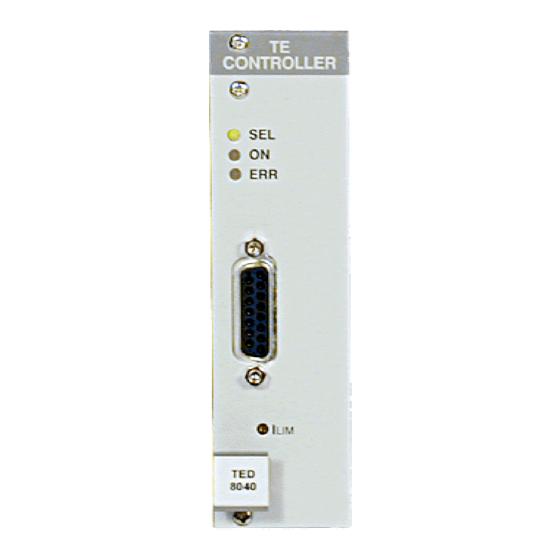
Page 18: Operating Elements On Front Panel
1.5 Operating elements on front panel 1.5 Operating elements on front panel 1.5.1 The TED8xxx module Connector jack for the TEC element Potentiometer for I Figure 1 The front panel of the TED8xxx module NOTE This picture is valid for all temperature modules with one slot width. The module TED8080 with 8 A TEC current is of double width. -
Page 19: The Ted8080 Module
1.5 Operating elements on front panel 1.5.2 The TED8080 module TE CONTROLLER Connector jack for the TEC element Potentiometer for I Figure 2 The front panel of the TED8080 module Temperature module TED8xxx / page 12... -
Page 20: Pre-Settings
1.6 Pre-settings 1.6 Pre-settings 1.6.1 Setting the limit values To protect the TEC element the maximum delivered current may be limited. Two limit values will be possible: hardware limit and software limit. Hardware limit I The hardware limit I is set with the potentiometer I at the front of the module TED8xxx. - Page 21 1.6 Pre-settings Software limit I The software limit I is set or changed manually in the channel menu of the module or with a control computer via IEEE 488 interface. Dsh = 25.0% TE off I = 1.842 A Iconst Imax= 0.800 A CHANGE Software limit I The software limit I...
-
Page 22: Connecting Components
1.7 Connecting components 1.7 Connecting components 1.7.1 Pin assignment TED8xxx (female 15-pole D-SUB) Figure 3 TED8xxx pin assignment Connector TEC element 5,6,7 TEC element + 13,14,15 TEC element - (ground) Voltage detector TEC element + Voltage detector TEC element - Status display Status-LED anode Status-LED cathode (ground) -
Page 23: Pin Assignment Ted8Xxx-Pt
1.7 Connecting components 1.7.2 Pin assignment TED8xxx-PT (female 15-pole D-SUB) Figure 4 TED8xxx-PT pin assignment Connector TEC element 5,6,7 TEC element + 13,14,15 TEC element - (ground) Voltage detector TEC element + Voltage detector TEC element - Status display Status-LED anode Status-LED cathode (ground) Temperature sensor PT-100 current source - (ground) -
Page 24: Pin Assignment Ted8Xxx-Kryo
1.7 Connecting components 1.7.3 Pin assignment TED8xxx-Kryo (female 15-pole D-SUB) Figure 5 TED8xxx pin assignment Connector Heater element 5,6,7 Heater element + 13,14,15 Heater element - (ground) Voltage detector heater element + Voltage detector heater element - Status display Status-LED anode Status-LED cathode (ground) Temperature sensor PT-1000 current source - (ground) -
Page 25: Connecting A Thermistor
1.7 Connecting components We recommend to use separate lines drilled in pairs (twisted pair) in a common shield for TEC current and temperature sensor. The shield has to be connected to ground (pin 13,14,15). 1.7.4 Connecting a thermistor The thermistor is connected between pin 3 and pin 4. Figure 6 Connecting a thermistor 1.7.5 Connecting an AD590... -
Page 26: Connecting An Lm335
1.7 Connecting components 1.7.6 Connecting an LM335 The IC-temperature sensor LM335 is connected between pin 10, pin 11 (+) and pin 8 (-). LM 335 Figure 8 Connecting an LM335 1.7.7 Connecting a PT-100 or PT-1000 sensor (option PT or Kryo) PT-1000 Figure 9 Connecting a PT-100 or PT-1000 sensor (option PT or Kryo) -
Page 27: Connecting Tec Elements With Voltage Detector
1.7 Connecting components What in case of a faulty sensor The measurement input (Pin 10 and 11) is connected internally to the output of the current source (Pin 3 and 4) via a 1 kΩ resistance. Therefore the following behavior can be expected with a faulty sensor: •... - Page 28 1.7 Connecting components Figure 10 4-pole measurement of TEC voltage ! Attention! An reverse poled TEC element may lead to thermal runaway and destruction of the connected components. Refer to section 1.7.9, ”Polarity check of the TEC element” starting on page 22) Temperature module TED8xxx / page 21...
-
Page 29: Polarity Check Of The Tec Element
1.7 Connecting components 1.7.9 Polarity check of the TEC element Pre-settings • Connect TEC element and temperature sensor. The sensor must be in good thermal contact to the active surface of the TEC element. • Switch on the PRO8000 (-4) / PRO800 system. •... -
Page 30: Optimization Of Temperature Control
1.8 Optimization of temperature control 1.8 Optimization of temperature control 1.8.1 Principle set-up and function When diode laser systems are tempered mainly the following components are involved: • The laser diode to be tempered • A temperature sensor (thermistor / AD590 / LM335) •... -
Page 31: Pid Adjustment
1.8 Optimization of temperature control If the internal power dissipation in the laser changes (e.g. the laser current is changed) also the temperature gradient between laser and sensor will change. This results in a measurement error depending on the mechanical set-up laser/sensor. - Page 32 1.8 Optimization of temperature control P-share • Change repeatedly between set temperatures of 18 °C and 22 °C while observing the settling behavior of the actual temperature. Increase the P-share gradually. Higher values will increase the settling speed, to high values make the system oscillate. The P-share has been set correctly when the actual temperature remains stable near the set temperature after only 2-3 overshoots.
-
Page 33: Operating The Ted8Xxx
2.1 Functions in the main menu 2 Operating the TED8xxx Before switching on the TEC current please refer to chapter 1.6, "Pre-settings" on page 13 NOTE With modules of the TED8xxx series all settings are executed at once. It is not necessary to confirm the set values. -
Page 34: Selecting A Module
2.1 Functions in the main menu 2.1.2 Selecting a module Select a module for further input by setting the cursor to the channel number of the desired module with the softkeys Pressing will lead to the channel menu (Refer to chapter 2.2, "Functions in the channel menu" starting on page 29) 2.1.3 Setting the temperature To change the set temperature in the main menu the corresponding module is selected with the cursor (here: CH2):... - Page 35 2.1 Functions in the main menu Pressing the key (TUNE) will turn the cursor to the right: CH1 T= +18.000°C CH2 T= +20.000°C TUNE: The temperature can be adjusted by means of the tuning knob. Press to make the new settings valid. NOTE If the TEC current is switched ON, the actual temperature is displayed.
-
Page 36: Functions In The Channel Menu
2.2 Functions in the channel menu 2.2 Functions in the channel menu The channel menu is reached from the main menu by pressing Hit again to return to main menu. 2.2.1 Display In the channel menu all parameters of the selected module are shown: channel no. - Page 37 2.2 Functions in the channel menu Thermistor Pt100 Kryo AD590 Thermistor PT100 low range AD590 Rs=100.00 Ω Rs=300.00 Ω Th.range=low Ra=100.25 Ω Ra=298.45 Ω Exponential Rwin=10.50 Ω Rwin=10.50 Ω Ω = 9.1234 k Ω = 9.1234 k Ω Rwin=6.1234k Ω R0= 10.000 k B = 3900.0 T0= 25.000 °C...
-
Page 38: Changing Parameters
2.2 Functions in the channel menu 2.2.2 Changing parameters To set or change a numerical set parameter in the channel menu the respective line is selected with the cursor: Example: Twin is to be changed: = 22.000 °C TE on = 22.000 °C Th lo Twin= 5.60 °C... -
Page 39: Selecting The Type Of The Sensor
2.2 Functions in the channel menu 2.2.3 Selecting the type of the sensor The sensor type can be selected in the TED8xxx modules by selecting the line "Thermistor" respectively "AD590". AD590 = AD590 and LM335 families Thermistor = Thermistor. The corresponding range has to be selected The modules with Pt-100 option let you choose between Thermistor = Thermistor. -
Page 40: Selecting The Range Of A Thermistor
2.2 Functions in the channel menu 2.2.4 Selecting the range of a thermistor The range of the thermistor can be selected up to 20 kΩ or 200 kΩ Th.range=low = 20 kΩ range Th.range=high = 200 kΩ range Select the desired range and press 2.2.5 Selecting the range of the Pt-1000 (Kryo-option) In menu-line “range“... -
Page 41: Calibrating The Thermistor
2.2 Functions in the channel menu 2.2.6 Calibrating the thermistor 2.2.6.1 Select the calculation method If the relation between thermistor resistance and corresponding thermistor temperature is known all inputs and outputs can be calibrated in °C. Two methods to calculate the resistance from temperature are implemented: •... - Page 42 2.2 Functions in the channel menu 2.2.6.2 Exponential method The dependency of resistance on temperature of an NTC-thermistor and vice versa is described by the formula: − ∗ ⇔ (temperatures in Kelvin) with: R Thermistor nominal resistance at temperature T Nominal temperature (typ.
- Page 43 2.2 Functions in the channel menu 2.2.6.3 Steinhart-Hart method A further way of representing the relation between temperature and thermistor resistance is the method according to Steinhart-Hart ∗ ∗ (ln( with the three parameters C and C To change the three parameters select them one by one and set them to the desired value.
-
Page 44: Calibration Of The Pt-1000 Sensor (Kryo Option)
2.2 Functions in the channel menu 2.2.7 Calibration of the Pt-1000 sensor (Kryo option) The Pt-1000 sensor itself is factory calibrated and does not need any further calibration. The calculation of the temperature by means of the sensor-resistance is done according to DIN IEC 751. At very low temperatures however (below 200K), there are small differences between the DIN IEC 751 model and the real sensor resistance / temperature. -
Page 45: Setting A Temperature Window
2.2 Functions in the channel menu 2.2.8 Setting a temperature window A temperature window can be defined to operate laser diodes in a well defined temperature region. This function can be used especially with an external control computer. In local mode the “ERR” led will light up, if the temperature leaves the window. - Page 46 2.2 Functions in the channel menu For adjustment of the parameters it is sometimes necessary to switch off the I-share completely. There is a separate switch parameter for this purpose: Ishare = ON/OFF You can toggle the function with the right softkey. Press to end input.
-
Page 47: Switching On And Off
2.3 Switching on and off 2.3 Switching on and off First select the TED module in the main menu (the LED “SEL” must light) (Refer to chapter 2.1.2, "Selecting a module" on page 27) ! Attention ! Before switching on a temperature module TED8xxx first set the TEC limit current I (hardware limit) for the applied TEC element with a screwdriver. -
Page 48: Error Messages
2.4 Error messages 2.4 Error messages Error messages are shown in the bottom line of the display not regarding, if you are in the main menu or in the channel menu. If an error occurs, the display shows for example: = 22.000 °C TE on = 22.000 °C... - Page 49 2.4 Error messages If the error occurs during operation it is written in brackets: <CH3 Sens.fail> If the error occurs when switching on the module it is written in cursor arrows: CH3 No Sensor If an error occurs, it has to be acknowledged by pressing " "...
-
Page 50: Communicating With A Control Computer
3.1 General notes on remote control 3 Communicating with a control computer 3.1 General notes on remote control The description of the mainframe of the PRO8000 (-4) / PRO800 includes all instructions of how to prepare and execute the programming of the system via IEEE 488 computer interface. -
Page 51: Nomenclature
3.1 General notes on remote control 3.1.1 Nomenclature Program messages (PC ⇒ PRO8000 (-4)) are written in inverted commas "*IDN?" Response messages (PRO8000 (-4) ⇒ PC) are written in brackets: [:SLOT 1] There is a decimal point: 1.234 Parameters are separated by comma: "PLOT 2,0"... - Page 52 3.1 General notes on remote control Numeric response data Type 2 (<NR2>) Is a numerical value with or without sign in floating point notation without exponent. Examples: 1.1 or +1.1 or -22.1 or 14356.789432 (Refer to IEE488.2 (8.7.3)) Numeric response data Type 3 (<NR3>) Is a numerical value with or without sign in floating point notation with exponent with sign .
-
Page 53: Commands
3.2 commands 3.2 commands 3.2.1 Select the module slot ":SLOT <NR1>" Selects a slot for further programming <Nr1>=1…8 (PRO8000), 1…2 (PRO800) ":SLOT?" Queries the selected slot [:SLOT <NR1><LF>] 3.2.2 Thermistor calibration (exponential method) (Not for TED8xxx with Kryo-option!) Programming: ":CALTB:SET <NR3>" Program the energy constant B ":CALTR:SET <NR3>"... - Page 54 3.2 commands ":CALTB:MAX?" Reading the maximum B allowed [:CALTB:MAX <NR3><LF>] ":CALTR:MAX?" Reading the maximum R allowed [:CALTR:MAX <NR3><LF>] ":CALTT:MAX?" Reading the maximum T allowed [:CALTT:MAX <NR3><LF>] Refer to section 2.2.6, “Calibrating the thermistor” on page 34) NOTE The selection on how the sensor calibration is done (exponential method or Steinhart-Hart method) is done by the order in which you transmit the coefficients.
-
Page 55: Thermistor Calibration (Steinhart-Hart Method)
3.2 commands 3.2.3 Thermistor calibration (Steinhart-Hart method) (Not for TED8xxx with Kryo-option!) Programming: ":CALTC1:SET <NR3>" Set the Steinhart-Hart coefficient C1 ":CALTC2:SET <NR3>" Set the Steinhart-Hart coefficient C2 ":CALTC3:SET <NR3>" Set the Steinhart-Hart coefficient C3 Reading: ":CALTC1:SET?" Read the Steinhart-Hart coefficient C1 [:CALTC1:SET <NR3><LF>] ":CALTC2:SET?"... -
Page 56: Switching The I-Share On And Off (Integ)
3.2 commands 3.2.4 Switching the I-share on and off (INTEG) Programming: ":INTEG ON" Switching the I-share on ":INTEG OFF" Switching the I-share off Reading: ":INTEG?" Read status of the I-share [:INTEG ON<LF>] [:INTEG OFF<LF>] 3.2.5 Reading the TEC current (ITE) Programming: ":ITE:MEAS <NR1>"... -
Page 57: Programming The Tec Current Software-Limit (Limt)
3.2 commands 3.2.6 Programming the TEC current software-limit (LIMT) Programming: ":LIMT:SET <NR3>" Program the TEC software current -limit Reading: ":LIMT:SET?" Read the TEC current software-limit [:LIMT:SET <NR3><LF>] ":LIMT:MIN?" Read the minimum TEC software current - limit allowed [:LIMT:MIN <NR3><LF>] ":LIMT:MAX?" Read the maximum TEC software current –... -
Page 58: Reading The Tec Current Hardware-Limit (Limtp)
3.2 commands 3.2.7 Reading the TEC current hardware-limit (LIMTP) Reading: ":LIMTP:ACT?" Read the actual TEC hardware current –limit [:LIMTP:ACT <NR3><LF>] ":LIMT:MIN_W?" Read I - DAC = 0000 TE max [:LIMT:MIN_W <NR3><LF>] ":LIMT:MAX_W?" Read I - DAC = FFFF TE max [:LIMT:MAX_W <NR3><LF>] (Refer to Chapter 1.6.1, "Setting the limit values"... -
Page 59: Programming The Resistance Of The Temperature Sensor (Resi)
3.2 commands 3.2.8 Programming the resistance of the temperature sensor (RESI) Programming: ":RESI:SET <NR3>" Program the resistance of the temperature sensor (thermistor, PT100/PT1000) ":RESI:MEAS <NR1>" RESI as measurement value for “ELCH” on string position <NR1> (1..8) Reading: ":RESI:SET?" Read the set resistance of the sensor (thermistor,) [:RESI:SET <NR3><LF>] ":RESI:ACT?"... -
Page 60: Programming The Resistance Window (Rwin)
3.2 commands 3.2.9 Programming the resistance window (RWIN) Programming: ":RWIN:SET <NR3>" Program the resistance window Reading: ":RWIN:SET?" Read the set resistance window [:RWIN:SET <NR3><LF>] ":RWIN:MIN?" Read the minimum set resistance window allowed [:RWIN:MIN <NR3><LF>] ":RWIN:MAX?" Read the maximum set resistance window allowed [:RWIN:MAX <NR3><LF>] ":RWIN:MIN_W?"... -
Page 61: Selecting The Sensor (Sens)
3.2 commands 3.2.10 Selecting the sensor (SENS) Programming: ":SENS AD" Sensor is AD590 family ":SENS THL" Sensor is thermistor (20 kΩ range) ":SENS THH" Sensor is thermistor (200 kΩ range) ":SENS PT100" Sensor is PT-100 (only TED8xxx-PT) ":SENS PT1000L" Sensor is PT-1000 (only TED8xxx-Kryo), low region ":SENS PT1000H"... -
Page 62: Programming The Pid Shares (Sharep, -I, -D)
3.2 commands 3.2.11 Programming the PID shares (SHAREP, -I, -D) Programming: ":SHAREP:SET <NR3>" Program the P-share ":SHAREI:SET <NR3>" Program the I-share ":SHARED:SET <NR3>" Program the D-share Reading: ":SHAREP:SET?" Read the P-share [:SHAREP:SET <NR3><LF>] ":SHAREI:SET?" Read the I-share [:SHAREI:SET <NR3><LF>] ":SHARED:SET?" Read the D-share [:SHARED:SET <NR3><LF>] ":SHAREP:MIN?"... -
Page 63: Switching The Tec On And Off (Outp)
3.2 commands 3.2.12 Switching the TEC on and off (OUTP) Programming: ":TEC ON" Switching the TEC output on ":TEC OFF" Switching the TEC output off Reading: ":TEC?" Read status of the output [:TEC ON<LF>] [:TEC OFF<LF>] Temperature module TED8xxx / page 56... -
Page 64: Programming The Temperature (Temp)
3.2 commands 3.2.13 Programming the temperature (TEMP) Programming: ":TEMP:SET <NR3>" Program the temperature ":TEMP:MEAS <NR1>" Program temperature to be measurement value for “ELCH” on string position <NR1> (1..8) Reading: ":TEMP:SET?" Read the set temperature [:TEMP:SET <NR3><LF>] ":TEMP:ACT?" Read the actual temperature [:TEMP:ACT <NR3><LF>] ":TEMP:MIN?"... -
Page 65: Programming The Temperature Window (Twin)
3.2 commands 3.2.14 Programming the temperature window (TWIN) Programming: ":TWIN:SET <NR3>" Program the temperature window Reading: ":TWIN:SET?" Read the set temperature window [:TWIN:SET <NR3><LF>] ":TWIN:MIN?" Read the minimum set temperature window allowed [:TWIN:MIN <NR3><LF>] ":TWIN:MAX?" Read the maximum set temperature window allowed [:TWIN:MAX <NR3><LF>] ":TWIN:MIN_W?"... -
Page 66: Reading The Tec Voltage (Vte)
3.2 commands 3.2.14.1 Query type of module Reading: ":TYPE:ID? " Query type identification of the module (must be 223) [:TYPE:ID 223<LF>] ":TYPE:SUB? " Query sub-type of module : Normal module: 0 PT 100 option: 1 Kryo-option: [:TYPE:SUB <NR1><LF>] 3.2.15 Reading the TEC voltage (VTE) Programming: ":VTE:MEAS <NR1>"... -
Page 67: 1100
3.3 1100 ... 1199 TED8xxx error messages 3.3 1100 ... 1199 TED8xxx error messages [1103,"Over temperature"] Possible reason: Module temperature too high. Switch off the output and wait until the module has cooled down. Maintain proper air flow. [1104,"Wrong or no sensor"] Possible reason: Wrong or no sensor connected. -
Page 68: Status Reporting
3.4 Status reporting 3.4 Status reporting The TED8xxxx modules provide three 16 bit registers DEC, DEE and EDE (see Figure 13) together with four 8 bit registers ESR, STB, ESE and SRE (see Figure 14) of the mainframe to program various service request functions and status reporting. (Please refer to the IEEE488.2-1992 standard chapter 11) Figure 13 The TED8xxx device error registers DEC, DEE and EDE... - Page 69 3.4 Status reporting Output buffer ERROR Queue or serial poll Service Request Generation Figure 14 The PRO8000 (-4) / PRO800 register ESR, ESE, STB and SRE Temperature module TED8xxx / page 62...
-
Page 70: Standard Event Status Register (Esr)
3.4 Status reporting 3.4.1 Standard event status register (ESR) The bits of this register represent the following standard events: Power on This event bit indicates, that an off to on transition has occurred in the power supply. So it is high after turning on the device for the first time. -
Page 71: Status Byte Register (Stb)
3.4 Status reporting 3.4.3 Status byte register (STB) The bits of this register are showing the status of the PRO8000 (-4) / PRO800. RQS: Request service message: Shows, that this device has asserted SRQ (read via serial poll). Master summary status: Shows that this device requests a "*STB?"... -
Page 72: Reading The Stb By Detecting Srq
3.4 Status reporting 3.4.5 Reading the STB by detecting SRQ If an SRQ is asserted (see 3.4.4) bit 6 of the STB is set to logical 1, so that the controller can detect which device asserted the SRQ by auto serial polling. 3.4.6 Reading the STB by "*STB?"... -
Page 73: Device Error Condition Register (Dec)
3.4 Status reporting 3.4.8 Device error condition register (DEC) The bits of this register show the errors, that occur during operation (operation errors). The bits are active high. If the error disappears, the bits are reset to low. For the TED8xxx temperature controller modules bits 0, 4, 5, 6 and.8 are used: (0) Over temperature Temperature too high. -
Page 74: Device Error Event Enable Register (Ede)
3.4 Status reporting 3.4.10 Device error event enable register (EDE) The bits of the EDE are used to select, which bits of the DEE shall influence bit 3 (DES) of the STB. The 8 bits of the EDE are related by logical "AND" to the according 8 bits of the DEE. -
Page 75: Service And Maintenance
4.1 General remarks 4 Service and Maintenance 4.1 General remarks The TED8xxx modules do not need any maintenance by the user. If highest precision of measurements is vital to you, you should have recalibrated the TED8xxx module about every two years. Temperature module TED8xxx / page 68... -
Page 76: Troubleshooting
4.2 Troubleshooting 4.2 Troubleshooting In case that one module of your PRO8000 / PRO800 system shows malfunction please check the following items: $ Module does not work at all (no display on the mainframe): % Mainframe PRO8000 (-4) / PRO800 connected properly to the mains? &... - Page 77 If you don’t find the error source by means of the trouble shooting list or if more modules work erratic please first connect Thorlabs-Hotline (blueline@thorlabs.com) before sending the whole PRO8000 (-4)/800 system for checkup and repair to Thorlabs-Germany. (refer to section 5.4, “Addresses ” on page 75 Temperature module TED8xxx / page 70...
-
Page 78: Listings
5.1 List of abbreviations 5 Listings 5.1 List of abbreviations The following abbreviations are used in this manual: Analog to Digital Converter ASCII American Standard Code for Information Interchange CLeaR Carriage Return Character Response Data Digital to Analog Converter D-Share Differential share Device Clear Device Error Condition Register... - Page 79 5.1 List of abbreviations Master Summary Status Over TemPerature Personal Computer P-Share Proportional share PT100 PlaTinum sensor, 100 Ω nominal resistance PlaTinum sensor, 1000 Ω nominal resistance PT1000 ReQuest Service Message Selected Device Clear SELect Service Request Enable Register Service ReQuest STatus Byte Register Soft Ware ThermoElectric Cooler (Peltier Element)
-
Page 80: List Of Figures
5.2 List of figures 5.2 List of figures Figure 1 The front panel of the TED8xxx module .......... 11 Figure 2 The front panel of the TED8080 module ......... 12 Figure 3 TED8xxx pin assignment..............15 Figure 4 TED8xxx-PT pin assignment ............16 Figure 5 TED8xxx pin assignment.............. -
Page 81: Certifications And Compliances
Compliance demonstrated using high-quality shielded interface cables, including with CAB4x series cables installed at the TEC OUT ports. Compliance demonstrated with the TED8x series modules installed in Thorlabs GmbH PRO8x series mainframes. Emissions, which exceed the levels required by these standards, may occur when this equipment is connected to a test object. -
Page 82: Addresses
5.4 Addresses 5.4 Addresses Thorlabs GmbH Gauss-Strasse 11 D-85757 Karlsfeld Fed. Rep. of Germany Tel.: +49 (0)81 31 / 5956-0 Fax: +49 (0)81 31 / 5956 99 Email: profile@thorlabs.com Internet: http://www.thorlabs.com Technical Hotline: blueline@thorlabs.com Our company is also represented by several distributors and sales offices throughout the world.
Need help?
Do you have a question about the TED8 Series and is the answer not in the manual?
Questions and answers