Table of Contents
Advertisement
Advertisement
Table of Contents

Related Manuals for THORLABS TC200


Summary of Contents for THORLABS TC200
- Page 1 TC200, TC200-EC Temperature Controller User Guide...
-
Page 2: Table Of Contents
Temperature Controller Table of Contents Chapter 1 Warning Symbol Definitions ....................1 Description ..........................2 Chapter 2 Safety............................3 Chapter 3 Features ..........................4 Chapter 4 4.1. Front and Rear Panel ....................4 4.2. Operation ........................5 Stand-Alone Operation ......................7 Chapter 5 5.1. - Page 3 11.2. Alternate Use of the Auxiliary Output..............29 Chapter 12 Specifications ........................30 12.1. Accessories ......................30 Chapter 13 Warranty ..........................31 Chapter 14 Regulatory ........................... 32 Chapter 15 Certifications and Compliance ..................33 Chapter 16 Thorlabs Worldwide Contacts ................... 34...
-
Page 4: Chapter 1 Warning Symbol Definitions
Warning Symbol Definitions Chapter 1 Note: Throughout this manual, references to temperature are with respect to °C, even though the TC200 can be set to display °C, °F, or K. Below is a list of warning symbols you may encounter in this manual or on your device. -
Page 5: Chapter 2 Description
Description Chapter 2 The TC200 Temperature Controller is a bench top controller intended for use with resistive heating elements rated up to 18 Watts. This general purpose instrument can drive various types of heaters, including foil and resistive coil types. It accepts feedback from either positive or negative temperature coefficient thermistors, has programmable P, I, and D gains, and will display the temperature in °C, °F, or K. -
Page 6: Chapter 3 Safety
Thorlabs provides the proper 120 VAC power input cable with each TC200 for use in the United States and the proper 230 VAC power input cable with each TC200-EC for use in Europe. If using this unit anywhere else, the user will need to supply a properly grounded power cable to power the unit. -
Page 7: Chapter 4 Features
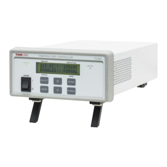
4.1. Front and Rear Panel Figure 1 TC200 Front and Rear Panel 1. Power Switch – Turns the unit On and Off. 2. Power On Indicator – When this text is lit, power is applied to the unit. 3. LCD Display – Provides status and temperature information when in the main screen as shown above. -
Page 8: Operation
The TUNE function allows the user to tune the output of the TC200 exactly to the set-point value without having to adjust the P, I, or D controls. Ideally the I gain and D gain settings should be set to zero and only the P gain should be adjusted to provide a stable temperature. - Page 9 9. Maximum Temperature Shutdown – Based on the setting of the TMAX parameter discussed above, if the TC200 reads back a temperature value that equals or exceeds TMAX, the output relay will be opened and !TMAX! will be displayed in the MODE field of the main LCD display screen. The controller, however, will remain enabled.
-
Page 10: Chapter 5 Stand-Alone Operation
0.1°, and pressing the DOWN arrow will decrement the temperature by 0.1°. As with all of the numeric adjustments that can be done on the TC200, holding the arrow keypads down will accelerate the rate of increase or decrease the longer the arrow keypad is held down. -
Page 11: Turning The Heater Off
Temperature Controller Chapter 5: Stand-Alone Operation 5.5. Turning the Heater Off When necessary, the heater output can be turned off by either pressing and releasing the ENABLE keypad or pressing the POWER switch to the OFF ( 0 ) position, which will turn off the entire unit. ... -
Page 12: Selecting And Adjusting The Gains: P, I, D, And Tune
Special Functions – While in the Main Display screen, the SELECT keypad will perform two special functions: If you are using Thorlabs’ gas cell heaters in conjunction with the auxiliary output, pressing the SELECT key will momentarily display the auxiliary heater’s temperature. This function only works when the PTC100 sensor is selected. -
Page 13: Selecting The Temperature Sensor: Ptc100 Vs. Ptc1000 Vs. Th10K
4. Press the ENTER keypad once. 5. The MAIN screen will now be displayed. 6. Please refer to TUNE Function on page 14 for more information on tuning the TC200. 5.6.3. Selecting the Temperature Sensor: PTC100 vs. PTC1000 vs. TH10K Programming the Appropriate Temperature Sensor 1. -
Page 14: Selecting And Adjusting The Maximum Temperature And Power: Tmax And Pmax
Temperature Controller Chapter 5: Stand-Alone Operation 5.6.4. Selecting and Adjusting the Maximum Temperature and Power: TMAX and PMAX Changing the TMAX or PMAX Values 1. While in the Main Screen display, press the MODE keypad three times. 2. The screen will now display the TMAX and PMAX values. 3. -
Page 15: Selecting The Operating Mode: Normal Vs. Cycle
Temperature Controller Chapter 5: Stand-Alone Operation 5.6.6. Selecting the Operating Mode: NORMAL vs. CYCLE Changing the Operating Mode 1. While in the Main screen press the MODE keypad five times. 2. The screen will now display “NORMAL MODE” and “CYCLE MODE”. 3. -
Page 16: Cycle Mode
Temperature Controller Chapter 5: Stand-Alone Operation 5.7. CYCLE Mode The STOP temperature determines the final temperature that the system will try to go to in the amount of time determined by the Ramp time value. The RAMP time is how long it will take to go from a starting temperature to a stopping temperature. ... -
Page 17: Tune Function
STOP temperature values will be changed to match TMAX. If the TC200 reads back a temperature value that equals or exceeds TMAX, the output relay will be opened and !TMAX! will be displayed in the MODE field of the Main Display screen. The controller, however, will remain enabled. -
Page 18: Sensor Alarm
Observe the TEMP ACTUAL value displayed on the TC200. If the sensor has been properly programmed, the display will show a value corresponding to the room ambient temperature. -
Page 19: Chapter 6 Operating From A Computer
TC200 Software. Prior to connecting the TC200 to your computer, the USB drivers must be installed. Insert the CD packad with the TC200 into the CD drive of your PC and you should be presented with the following “AutoPlayr” dialog box: Click the Launch Thorlabs, Inc. -
Page 20: Software And Usb Driver Installation
Admin Control – Windows XP Figure 3 You may choose which user(s) are granted access to the TC200 software. To install the software for all users, you must have administrative rights, if you do not, please contact your Computer Admin. If you have trouble installing the software as noted above, you may have to Un-Check “Protect my computer and data from... - Page 21 6.2.1 for further details. When the TC200 is connected to the Computer, it is assigned a “COM Port Number”. It may be necessary to know which “COM” port number the Computer has assigned the TC200, since the software looks for particular number in order to communicate.
- Page 22 Temperature Controller Chapter 6: Operating from a Computer Figure 5 Windows 7 3. In Device Manager, double-click Ports (COM & LPT) 4. Find “USB Serial Port” and note the COM Port Number in parenthesis. Figure 6 Windows XP Rev N, July 31, 2017 Page 19...
-
Page 23: The Command Line Interface
Flow Control None 2. Apply AC power to the TC200, turn the TC200 on (see page 7), and wait for the unit to complete its power- on initialization. 3. Press the ENTER keypad on your computer. If the connection is working, you will receive the following... -
Page 24: Terminal Commands And Queries
The basic command structure consists of two types: commands and queries, both of which are sent to the TC200 by a carriage return (CR) or by pressing the ENTER key on your computer. Most commands follow a format of: Command = Argument (CR) ... - Page 25 Temperature Controller Chapter 6: Operating from a Computer Command/Query Function Description If the unit is disabled, ens will enable the unit. Toggle Enable State Otherwise, it will disable. tset Set Temperature tset=nnn.n (20.0 to 200.0 to TMAX) tset? Get TEMP SET Value Returns the current value of TEMP SET.
- Page 26 Temperature Controller Chapter 6: Operating from a Computer The Status Byte The “Status Byte” is an 8-bit hexadecimal value that is returned as part of the stat? query. Each bit corresponds to the following definitions to provide a snapshot of the status of the unit at any given time: Status Byte Definitions Bit 0 0 = Disabled...
- Page 27 Temperature Controller Chapter 6: Operating from a Computer The Configuration Command Typing config? Into the command line interface will return a list of all of the pertinent set up parameters to allow a user to view all items at a glance. The following is a typical return: >...
-
Page 28: Chapter 7 Output Connector Pin-Outs
Reserved (Do Not Connect to this Pin) Pin 4 Sensor Input (+) Pin 5 Sensor Input (Ground) Pin 6 Reserved (Do Not Connect to this Pin) Use HIROSE connector HR10A-7P-6P (73) to mate with the TC200 output connectors. Rev N, July 31, 2017 Page 25... -
Page 29: Chapter 8 Temperature Sensor Specifications
Temperature Sensor Specifications Chapter 8 The TC200 is compatible with two types of Platinum Thermistors: PT100 and PT1000. The TC200 is also compatible with the TH10K thermistor. The following specifications are used for determining the set-point and read back values for these types of thermistors. -
Page 30: Chapter 9 Troubleshooting
Temperature Controller Chapter 9: Troubleshooting Troubleshooting Chapter 9 The following table describes some typical problems that may be encountered while using the TC200 and possible solutions to these problems. Problem Solution 1. Make sure AC line cord is fully inserted into the AC Input receptacle and plugged into an outlet providing 100 to 240 VAC. -
Page 31: Chapter 10 General Maintenance
10.3. General Maintenance Aside from the AC Input fuses, there are no user-serviceable parts in the TC200. If you suspect something has failed on the unit, and if you have first referred to Troubleshooting on page 27, please contact Thorlabs for advice on returning the unit for evaluation. -
Page 32: Chapter 11 Auxiliary Output
Determine the main heater by connecting both heaters to the unit, setting the target temperature, and enabling the TC200. Once the main heater starts to show an increase in temperature, press the SELECT keypad to view the Auxiliary temperature. If the Auxiliary temperature is greater than the Main temperature, disable the heater, turn off the power, and exchange the two heaters by connecting the original main heater into the Auxiliary Output. -
Page 33: Chapter 12 Specifications
Universal input 50 – 60 Hz; no line switching required. The TEC200 is supplied with a 115 V parallel blade line cord for North American use only, while the TC200-EC is shipped with a 230 VAC line cord for European use. -
Page 34: Chapter 13 Warranty
Thorlabs, Inc. warrants the material and production of the TC200 Temperature Controller for a period of 24 months from the date of shipment. During this warranty period, Thorlabs, Inc. will repair or exchange any units found to be defective in material or workmanship. -
Page 35: Chapter 14 Regulatory
Waste Treatment is Your Own Responsibility If you do not return an “end of life” unit to Thorlabs, you must hand it to a company specialized in waste recovery. Do not dispose of the unit in a litter bin or at a public waste disposal site. -
Page 36: Chapter 15 Certifications And Compliance
Temperature Controller Chapter 15: Certifications and Compliance Certifications and Compliance Chapter 15 Category Standards or Description Meets intent of Directive 89/336/EEC for Electromagnetic EC Declaration of Conformity – Compatibility. Compliance is given to the following specifications as listed in the Official Journal of the European Communities: EMC requirements for Class A electrical equipment for measurement, -EN 61326 control, and laboratory use, including Class A Radiated and Conducted... -
Page 37: Chapter 16 Thorlabs Worldwide Contacts
Temperature Controller Chapter 16: Thorlabs Worldwide Contacts Thorlabs Worldwide Contacts Chapter 16 USA, Canada, and South America UK and Ireland Thorlabs, Inc. Thorlabs Ltd. 56 Sparta Avenue 1 Saint Thomas Place, Ely Newton, NJ 07860 Cambridgeshire CB7 4EX Great Britain... - Page 38 www.thorlabs.com...
Need help?
Do you have a question about the TC200 and is the answer not in the manual?
Questions and answers