
Related Manuals for THORLABS TED350


Summary of Contents for THORLABS TED350
- Page 1 Operation Manual Thorlabs Instrumentation Temperature Controller TED350(-IEEE) 2007...
- Page 2 Version: 2.14 Date: 07.02.2007 © Copyright 2007, Thorlabs, Germany...
-
Page 3: Table Of Contents
Contents Page General description of the TED350 controller 1.1 Packing List 1.2 Safety 1.3 General functions 1.3.1 Protections for the TEC element 1.3.2 Description of operation 1.4 Technical data 1.5 Operating elements 1.5.1 Front panel 1.5.2 Back panel 1.6 Pre-settings 1.6.1... - Page 4 2.2.2 PID adjustment Communication with a control computer (TED350-IEEE) 3.1 IEEE488 interface (TED350-IEEE) 3.1.1 IEEE 488 Interface subsets 3.1.2 Setting up the interface 3.1.3 Connecting the PC 3.1.4 IEEE488 bus commands 3.2 Before Programming 3.2.1 Nomenclature 3.2.2 Program and response messages 3.2.3...
- Page 5 3.6.8 TEC current (ITE) 3.6.9 Reading the temperature/resistance window (WIN) 3.6.10 Reading the TEC voltage (VTE) 3.7 Error messages of the TED350 3.7.1 General errors 3.7.2 TED350 operation error messages 3.8 Status reporting 3.8.1 Standard event status register (ESR) 3.8.2 Standard event status enable register (ESE) 3.8.3...
- Page 6 Thorlabs This part of the instruction manual contains specific information on how to operate the temperature controller TED350. A general description is followed by explanations of how to operate the unit manually. You will also find information about remote control via the optional IEEE 488 computer interface.
-
Page 7: General Description Of The Ted350 Controller
Before applying power to your TED350 system make sure that the protective conductor of the 3 conductor mains power cord is cor- rectly connected to the protective earth contact of the socket outlet! - Page 8 EN 50 082-1. Attention The temperature controller TED350 must not be operated in explo- sion endangered environments! TED350 / page 2...
-
Page 9: General Functions
1.3 General functions 1.3 General functions 1.3.1 Protections for the TEC element To protect the connected TEC elements and the laser diodes the TED350 has the following protective circuits: • Limit of the TEC current in all operating modes Protection against thermal destruction. -
Page 10: Description Of Operation
1.3 General functions 1.3.2 Description of operation The TED350 has an input for IC temperature sensors of the AD590/592 or LM35/135/335 series as well as an input for thermistors. When thermistors are used you can choose between two resistance ranges (maximum resistance of the thermistor 20kΩ... -
Page 11: Technical Data
1.4 Technical data 1.4 Technical data (All technical data are valid at 23 ± 5°C and 45 ±15% humidity) Note: Technical data in remote control mode applies to TED350-IEEE only. General Data Line voltage 100 V / 115 V / 230 V (-10%, +15 %) (fixed) Line frequency 50 ... - Page 12 E.g. for a typical thermistor at a set point of 10kΩ (25°C), a 0.5Ω stability translates into about 1mK temperature stability. At a set point of 5kΩ (38°C), the stability is about 2mK. TED350 / page 6...
- Page 13 Computer Interface (TED350-IEEE) Setting resolution 16 Bit Measurement resolution 11 ... 18 Bit Configurable from 11 Bit + sign (sample rate 18/s) to 18 Bit + sign (sample rate 2/s), see chapter 3.4.4, “Oversampling rate” on page 41 TED350 / page 7...
-
Page 14: Operating Elements
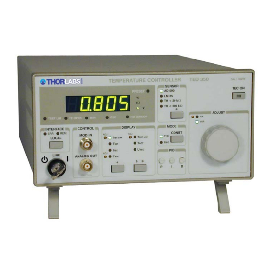
TEC output current ON / OFF switch Mains power control switch Modulation input and analog voltage output (BNC) Display selection field Operating mode selection: Const. current / const. temperature (resistance) PID-temperature control loop settings Main dial knob (10 turn) TED350 / page 8... -
Page 15: Back Panel
IEEE488 interface jack Mains voltage selector Fix: Set values determined by potentiometers, Var: Adjustable by main dial Unit wakeup settings (DIP-switch) TEC output jack (15-pin D-SUB jack) DIP-switch for interface settings Mains jack with fuse holder TED350 / page 9... -
Page 16: Pre-Settings
5.000°C the window will reach from 5°C below the set value to 5°C above the set value. • Activate this function with DIP switch 4 (Refer to chapter 2.1.9 on page 22) TED350 / page 10... -
Page 17: Connecting Components
Voltage detector TEC element (+) Voltage detector TEC element (-) Status indicator Status-LED (+) Status-LED (-), ground Temperature sensor Thermistor (-), ground Thermistor (+) AD590/592 (-), (Pt-100 -) AD590/592 (+), (Pt-100 +) Supply voltage for Thorlabs-mounts TED350 / page 11... -
Page 18: Connecting A Thermistor
1.7 Connecting components The TEC element and the temperature sensor must be connected to the output jack at the rear of the TED350 according to the shown pin assignment with shielded cables. The shielding of the cable must be connected to ground (pin 13,14,15). -
Page 19: Connecting A Temperature Sensor Ad590 Or Ad592
1.7.4 Connecting a temperature sensor LM135 or LM335 The IC-temperature sensor of the LM135 family is set up between pin 8, 10 and 11. These sensors translate the temperature into an equivalent current that can be displayed and set directly in °C. TED350 / page 13... -
Page 20: Connecting An Lm35
The IC-temperature sensor of the LM35 series is set up between pin 10, pin 11 and pin 8. These sensors will map the temperature into an equivalent voltage that can be displayed and set directly in °C. LM35 Figure 7 Connecting an LM35 TED350 / page 14... -
Page 21: Connecting The Pt-100 (Option)
1.7 Connecting components 1.7.6 Connecting the Pt-100 (option) The TED350 with the Pt-100 option can use the following temperature sensors: Pt-100, AD590, AD592, LM135, LM335, thermistor An LM35 cannot be used. PT 100 Figure 8 Connecting the Pt-100 (option) Connect one side of the Pt-100 to pin 3 and 10, the other side to pin 4 and 11 of the D-SUB connector. - Page 22 TEC element. Then a slightly too high voltage is displayed. Figure 9 Connecting the TEC element Attention A TEC element connected with wrong polarity may lead to thermal runaway and destruction of the connected components. TED350 / page 16...
-
Page 23: Connecting The Status Indicator
• Connect TEC element and temperature sensor. The sensor must have good thermal contact to the active surface of the TEC element. • Switch on the TED350. Now follow the steps described in chapter 1.6, “Pre-settings“ on page 10. • Select the display T and select a suitable temperature (resistance). -
Page 24: Fine Tuning Of The Temperature
1.7 Connecting components Poling and value of the TEC current is insignificant here. 1.7.9 Fine tuning of the temperature The TED350 has an input for fine tuning of the temperature labeled MOD IN. voltage this input modifies value temperature (AD590/LM35/LM335-mode) or of the thermistor resistance (thermistor mode). -
Page 25: Operating The Ted350
2.1 Manual operation 2 Operating the TED350 2.1 Manual operation Attention Prior to switch on your TED350 please check if the line voltage set with the voltage selector at the rear panel corresponds to your mains voltage! 2.1.1 Selecting the sensor Three different types of sensors can be selected: •... -
Page 26: Selecting The Mode Of Operation
) are not defined and can not be displayed or even selected. With the output switched off and the display I selected the LED “PRESET“ indicates that the set value of the TEC current is displayed. TED350 / page 20... -
Page 27: The Output Analog Out
This jack can be used to supervise the temperature of a laser diode when using a LDC340 laser diode driver. Simply connect the corresponding jack of the Thorlabs LDC340 to this output of the TED350. Further details can be found in the operation manual of the LDC340. TED350 / page 21... -
Page 28: Fix / Var Selector
SW1 and SW2 select the default (wakeup) sensor when switching the unit on function AD 590 down TH 20kΩ down LM 35 down down TH 200kΩ SW3 selects the default (wakeup) mode of operation function const T/R down const I TED350 / page 22... - Page 29 SW5 selects whether the beeper is on or off function beeper on down beeper off SW6 selects whether the I-share of the regulator loop is active or not function I-share active down I-share off SW7 and SW8 are not used. TED350 / page 23...
-
Page 30: Optimization Of Temperature Control Loops
• In the heat sink is a heat flow between TEC element and environment. • The temperature difference in the TEC element can be controlled by the TEC current. This directly influences the heat flow in the copper bloc and in the heat sink. TED350 / page 24... - Page 31 Changes ambient temperature however will compensated well by the control loop since they will almost only have an effect on the heat slope between TEC element and cooling element. Possibility of optimization: best possible thermal design TED350 / page 25...
-
Page 32: Pid Adjustment
Temperature control loops are comparatively slow control loops with control oscillations in the Hertz range. PID adjustment optimizes the dynamic behavior. With the TED350 the three parameters P, I and D can be selected independently. Example of a PID adjustment (Preconditions: All limit values, all polarities have been set correctly, a suitable sensor is connected and selected, the ambient temperature is about 20 °C) - Page 33 Increase the I-share gradually by turning the corresponding potentiometer clockwise. Higher values will accelerate the settling to the set temperature. The I-share has been set correctly when the actual temperature settles optimally to the set temperature. TED350 / page 27...
-
Page 34: Communication With A Control Computer (Ted350-Ieee)
All analog values are read and written in SI units, i.e. A (not mA), W (not mW) etc. Letters may be written in small or capital letters. Attention Before programming a TED350 first set the limit value of the TEC current I (hardware limit) for the used TEC element with a TEC LIM screwdriver. -
Page 35: Ieee488 Interface (Ted350-Ieee)
The IEEE488 interface of the TED350-IEEE is based on the IEEE488.2 standard. This includes the IEEE488.1 standard for the hardware settings. There is a standard 24-pin IEEE488 jack at the rear of the unit. The address of the TED350 must differ from that of other devices on the IEEE488 bus. -
Page 36: Setting Up The Interface
3.1.2 Setting up the interface Address The device address of the TED350 can be changed by means of the IEEE488 DIP switch located on the rear side of the TED350. SW1 to SW5 have to be set according to Table 2: Address... - Page 37 IEEE 488 address setting NOTE The device address is valid after switching off and on again. Terminator The string terminator of the TED350 is preset to . This is fixed and <LF><EOI> cannot be changed. The TED350 will accept any combination of as terminator.
-
Page 38: Connecting The Pc
To guarantee a safe transmission of data the IEEE488 cable between two units should not be longer than 2 meters and the total cable length should not exceed 20 meters. The TED350-IEEE will automatically enter REMOTE mode after the first character is transferred. NOTE... -
Page 39: Ieee488 Bus Commands
To communicate via the IEEE488 bus the standard control signals [MLA], [MTA], [UNL], [UNT], [ATN], [REN], [SPE], [SPD] are used. If the control program for the TED350 is written in a basic language as e.g. BASIC these IEEE488 control signals are automatically transmitted to the TED350 according to the used driver software and do not have to be explicitly produced in the control program. - Page 40 [DCL] usually set back when switching the unit on. The TED350 will behave as if it has been switched on anew but will be in REMOTE mode. NOTE The command sets back all units connected to the IEEE488 bus.
-
Page 41: Before Programming
Blocks of message data are transferred between the controller and the TED350 during communications. Messages sent from the controller to the TED350 are called program messages and messages sent back from the TED350 to the controller are called response messages. If a program message contains a query command i.e. a command which requests a response the TED350 returns a response message. -
Page 42: Data Format
(Refer to IEEE488.2-1992 standard, chapter 8.7.3) Numeric response data Type 3 (<NR3>) Is a numerical value with or without sign in floating point notation with signed exponent. Examples: 1.1E+1 +1.1E-1 -22.1E+1 143.56789432E+306 (Refer to IEEE488.2-1992 standard, chapter 8.7.4) TED350 / page 36... -
Page 43: Common Commands And Queries
All set values will be reset to the default values. The output is switched off. 3.3.3 Self-test query Syntax: *TST? " " Response: Description: 0: Self-test finished successful. 3.3.4 Set Operation-complete bit Syntax: *OPC " " Description: The TED350 sets the OPC-bit in the Standard-Event-Status-Register. TED350 / page 37... -
Page 44: Operation-Complete Query
" Response: Description: 1: Operation completed. 3.3.6 Wait Syntax: *WAI " " Description: The TED350 will wait until the last operation is completed. 3.3.7 Event-Status-Enable-Register (ESE) Programming: Syntax: *ESE <NR1> " " Valid Range: 0..255 Default Value: 0 Description: Sets the Event-Status-Enable-Register (ESE). -
Page 45: Service-Request-Enable-Register (Sre)
3.3.10 Query Status-Byte-Register (STB) Syntax: *STB? " " Response: [<NR1>] Description: Queries the Status-Byte-Register (STB) and returns the content in decimal notation. Bit 6 (MSS) is set to 0 the other bits are kept un- changed. TED350 / page 39... -
Page 46: System Command Group
" :SYST:ANSW VALUE " " Default Value: FULL Description: When switched to " " the TED350 sends only the requested VALUE parameter without designator. Example: When requesting the actual TEC current with " " the :ITE:ACT? TED350 will only send instead of [5.123456E-02]... -
Page 47: Querying The Error Queue
Queries the error queue of the TED350. The reply consists of the following sequence: <Error No.>, "<Error text>". If the error queue is empty: will response. [0, "No error"] (Please refer to chapter 3.7, “Error messages of the TED350“ starting on page 49) 3.4.4 Oversampling rate Programming: Syntax: :SYST:OSR <NR1>... -
Page 48: Status Command Group
" Valid Range: 0...65535 Default Value: 0 Description: Sets the Device-Error-Event-Enable-Register (EDE). Reading: Syntax: :STAT:EDE? " " Response: [<NR1>] Description: Queries the Device-Error-Event-Enable-Register (EDE) and returns the content in decimal notation. The content is not modified. TED350 / page 42... -
Page 49: Ted350 Specific Commands
3.6 TED350 specific commands 3.6 TED350 specific commands 3.6.1 Temperature sensor (SENS) Programming: Syntax: (AD590 family) :SENS AD " " (LM35 family or Pt-100 option) :SENS LM " " (thermistor, 20 kΩ range) :SENS THL " " (thermistor, 200 kΩ range) :SENS THH "... -
Page 50: Switching The Tec On And Off (Tec)
3.6 TED350 specific commands 3.6.3 Switching the TEC on and off (TEC) Programming: Syntax: :TEC OFF " " :TEC ON " " Default Value: OFF Assumption: To switch the TEC on there must be no device errors (no sensor, tec open, over temperature, ...). -
Page 51: Temperature (Only Ad590 And Lm35) (Temp)
3.6 TED350 specific commands 3.6.6 Temperature (only AD590 and LM35) (TEMP) Programming: Syntax: :TEMP:SET <NR3> " " Valid Range: Depends on the instrument type. Default Value: 25 °C Assumption: The temperature sensor is set to AD590 or LM35. The operating mode is set to constant temperature / resistance. -
Page 52: Resistance (Only Thermistor) (Resi)
3.6 TED350 specific commands 3.6.7 Resistance (only thermistor) (RESI) Programming: Syntax: :RESI:SET <NR3> " " Valid Range: Depends on the instrument type and the selected tmperature sensor. Default Value: Depends on the selected thermistor range. Assumption: The temperature sensor is set to thermistor (high or low range). The operating mode is switched to constant temperature / resistance. -
Page 53: Tec Current (Ite)
3.6 TED350 specific commands 3.6.8 TEC current (ITE) Programming: Syntax: :ITE:SET <NR3> " " Valid Range: Depends on the instrument type. Default Value: 0 A Assumption: The operation mode is switched to constant current. Description: Sets the TEC current. Unit: [A]. -
Page 54: Reading The Temperature/Resistance Window (Win)
3.6 TED350 specific commands 3.6.9 Reading the temperature/resistance window (WIN) Syntax: :WIN:ACT? " " Response: [:WIN:ACT <NR3>] Description: Queries the actual temperature / resistance window. Depending on the temperature sensor the temperature window or the resistance window is retuned. Unit: [°C], [Ω] 3.6.10 Reading the TEC voltage (VTE) -
Page 55: Error Messages Of The Ted350
" recognized as valid command. [101, "Invalid character"] Category: Command Error Possible reason: ". This character sent to the TED350 does not belong to the " allowed set of characters. [102, "Invalid numeric parameter"] Category: Command Error Possible reasons: "... - Page 56 :TEC THL " [190, "Parser buffer overflow"] Category: Command Error Possible reason: The string sent to the TED350 was too long for the parser. [200, "Data out of range"] Category: Execution Error Possible reason: " sent to the TED350 but this...
-
Page 57: Ted350 Operation Error Messages
There is no data in the output buffer. [500, "IEEE488 receive buffer overflow"] Category: Device Error Possible reason: The string sent to the TED350 was too long for the IEEE488 receive buffer (250 char max). 3.7.2 TED350 operation error messages [1103, "Over temperature"] Category:... - Page 58 3.7 Error messages of the TED350 [1107, "No sensor change during TEC on allowed"] Category: Execution Error Possible reason: The type of sensor may not be changed during the output is switched on. [1110, "No setting of TEC current during constant temperature mode"]...
-
Page 59: Status Reporting
3.8 Status reporting 3.8 Status reporting The TED350 provides four 8 bit registers ESR, STB, ESE and SRE and three 16 bit registers DEC, DEE and EDE to program various service request functions and status reporting. (Please refer to the IEEE488.2-1992 standard chapter 11) - Page 60 3.8 Status reporting Temperature out of window (:STAT:DEC?) n: Slot number Figure 11 The device Error registers DEC, DEE and EDE TED350 / page 54...
-
Page 61: Standard Event Status Register (Esr)
"OR" so that any "hit" leads to a logical 1 in bit 5 (ESB) of the STB. As any bit of the STB can assert an SRQ every event (bit of the ESR) can be used to assert an SRQ. TED350 / page 55... -
Page 62: Status Byte Register (Stb)
3.8 Status reporting 3.8.3 Status byte register (STB) The bits of this register are showing the status of the TED350. RQS: Request service message: Shows that this device has asserted SRQ (red via serial poll). Master summary status: Shows that this device requests a service (read via "... -
Page 63: Reading The Stb By Detecting Srq
3.8.7 Reading the STB by serial poll If the controller does not support auto serial poll the service request can also be detected via manual serial poll. If bit 6 is logical 1 a service request was asserted. TED350 / page 57... -
Page 64: Device Error Condition Register (Dec)
Maintain proper air flow. (4) Temperature window The TED350 asserted a temperature window protection signal. The TED350 detected the TEC element to have a too high (5) Open circuit resistance or being not present. The TED350 detected no sensor connected to the output (6) No sensor jack. -
Page 65: Device Error Event Register (Dee)
8 bits of the DEE. These 8 results are combined by logical "OR" so that any "hit" leads to a logical 1 in bit 3 (DES) of the STB. As any bit of the STB can assert an SRQ every error (bit of the DEE) can be used to assert an SRQ. TED350 / page 59... -
Page 66: Hints For Setting Up Control Programs
3.9 Hints for setting up control programs The following flowcharts show the communication sequences between a control computer and a TED350 using the IEEE488 interface. Use this sequences to ensure a fast and secure communication. Flowchart for writing device commands... - Page 67 Is EAV-bit set ? Query error-queue (write “:SYST:ERR?“ to the device) Read device- Poll status byte message (ibrd ...) (ibrsp ...) Is FIN-bit set ? Read error-message (ibrd ...) Is EAV-bit set ? Figure 13 Read device messages flowchart TED350 / page 61...
- Page 68 When communication problems occur at the bus or in case of error messages that cannot be explained the evalua- tion of the data transfer between the TED350 and the control computer will then be possible without much effort.
-
Page 69: Maintenance And Repair
To maintain the specifications for a long period of time we would recommend to have the unit re-calibrated by every second year. Thorlabs The TED350 does not possess any components to be repaired by the user. If any disturbances in function should occur please contact our technical hotline Thorlabs before sending the device to (Germany) for repair. -
Page 70: Selecting The Line Voltage
4.3 Selecting the line voltage The line voltage can be selected with the line voltage selector on the rear of the TED350. The TED350 can be operated with 100V 115V and 230V (+15% , -10% each). Using a flat-blade screwdriver, turn the switch to the desired range by aligning the triangle with the appropriate voltage (100V, 115V, or 230V). - Page 71 • Put the fuse holder back until is has snapped in. • Execute a function test of the TED350 by switching it on. In case the TED350 could not be switched on despite the correct fuse being inserted please contact your supplier or Thorlabs.
-
Page 72: Troubleshooting
Unit does not work at all (no display on the mainframe): TED350 controller connected properly to the mains? Connect the TED350 to the power line, pay attention to the right voltage setting. TED350 controller turned on? Turn on the unit with the key mains-switch. - Page 73 :SENS: XY If you don’t find the error source by means of the trouble shooting list please first connect the before sending the TED350 for checkup and repair Thorlabs-Hotline to Thorlabs-Germany. (refer to section 6.7, “Addresses ” on page 76...
-
Page 74: Service
Disconnect Power. To avoid electrical shock, first switch off the TED350 power, and then disconnect the power cord from the mains power. With the TED350 turned over, remove the two screws that secure the cover to the chassis. Remove the unit by sliding it out of the cover. With the unit set upright, you will find the label depicting names, values and positions of internal fuses at the outer wall of the transformer section. -
Page 75: Appendix
6.1 Warranty 6 Appendix 6.1 Warranty warrants material and production of the TED350 for a period of 24 months Thorlabs starting with the date of shipment. During this warranty period will see to Thorlabs defaults by repair or by exchange if these are entitled to warranty. -
Page 76: Certifications And Compliances
Compliance demonstrated with CAB450 cable installed at the TEC Output port. Emissions, which exceed the levels required by these standards, may occur when this equipment is connected to a test object. Minimum Immunity Test requirement. MOD IN port capped at IEC 61000-4-3 test. TED350 / page 70... -
Page 77: Thorlabs "End Of Life" Policy (Weee)
6.3 Thorlabs “End of Life” policy (WEEE) As required by the WEEE (Waste Electrical and Electronic Equipment Directive) of the European Community and the corresponding national laws, Thorlabs offers all end users in the EC the possibility to return “end of life” units without incurring disposal charges. -
Page 78: Waste Treatment On Your Own Responsibility
6.3.1 Waste treatment on your own responsibility If you do not return an “end of life” unit to Thorlabs, you must hand it to a company specialized in waste recovery. Do not dispose of the unit in a litter bin or at a public waste disposal site. - Page 79 6.3 Thorlabs “End of Life” policy (WEEE) Figure 15 Crossed out “wheelie bin” symbol TED350 / page 73...
-
Page 80: List Of Acronyms
Institute for Electrical and Electronic Engineering I-Share Integral share Light Emitting Diode Line Feed Local Lockout Numeric Response data of type 1 Numeric Response data of type 2 Numeric Response data of type 3 Message AVailable) Master Summary Status TED350 / page 74... -
Page 81: List Of Figures
The service request and standard event registers Figure 11 The device Error registers DEC, DEE and EDE Figure 12 Device commands flowchart Figure 13 Read device messages flowchart Figure 14 Changing the mains fuse Figure 15 Crossed out “wheelie bin” symbol TED350 / page 75... -
Page 82: List Of Tables
Table 2 IEEE 488 address setting Table 3 Oversampling rate 6.7 Addresses For technical support or sales inquiries, please visit us at www.thorlabs.com/contact for our most up-to- date contact information. USA, Canada, and South America UK and Ireland Thorlabs, Inc.
Need help?
Do you have a question about the TED350 and is the answer not in the manual?
Questions and answers